WINCC
Bạn đang xem bản rút gọn của tài liệu. Xem và tải ngay bản đầy đủ của tài liệu tại đây (9.67 MB, 232 trang )
Service & Support
Answers for industry.
WinCC – Examples of integrated
engineering with STEP 7
WinCC
Application Description
y
April 2009
Warranty, Liability and Support
WinCC – Examples of integrated engineering with STEP 7 Entry ID: 34995306
Version V1.0 Issue 27.04.2009 2/232
Copyright © Siemens AG Copyright 2009 All rights reserved
Warranty, Liability and Support
Note
The Application Examples are not binding and do not claim to be
complete regarding the configuration, equipping and any eventuality. The
Application Examples do not represent customer-specific solutions. They
are only intended to provide support for typical applications. You are
responsible for ensuring that the described products are used correctly.
These Application Examples do not relieve you of the responsibility of
safely and professionally using, installing, operating and servicing
equipment. When using these Application Examples, you recognize that
we cannot be made liable for any damage/claims beyond the liability
clause described. We reserve the right to make changes to these
Application Examples at any time without prior notice. If there are any
deviations between the recommendations provided in these Application
Examples and other Siemens publications – e.g. Catalogs – the contents
of the other documents have priority.
We do not accept any liability for the information contained in this
document.
Any claims against us – based on whatever legal reason – resulting from
the use of the examples, information, programs, engineering and
performance data etc., described in this Application Example shall be
excluded. Such an exclusion shall not apply in the case of mandatory
liability, e.g. under the German Product Liability Act
(“Produkthaftungsgesetz”), in case of intent, gross negligence, or injury of
life, body or health, guarantee for the quality of a product, fraudulent
concealment of a deficiency or breach of a condition which goes to the root
of the contract (“wesentliche Vertragspflichten”). The damages for a breach
of a substantial contractual obligation are, however, limited to the
foreseeable damage, typical for the type of contract, except in the event of
intent or gross negligence or injury to life, body or health. The above
provisions do not imply a change of the burden of proof to your detriment.
It is not permissible to transfer or copy these Application Examples or
excerpts of them without first having prior authorization from Siemens
Industry Sector in writing.
If you have any questions concerning this document please e-mail us to the
following address:
Preface
WinCC – Examples of integrated engineering with STEP 7 Entry ID: 34995306
Version V1.0 Issue 27.04.2009 3/232
Copyright © Siemens AG Copyright 2009 All rights reserved
Preface
Objective of the application
This application is designed for users ...
• who gained initial experiences with WinCC already.
It conveys knowledge about the interaction of the individual SIMATIC
configuration tools and shows how their configuration can be made
easier.
Main contents of this application
The following main points are discussed in this application:
• TIA
• Prerequisites
• Creating a Project
• Tags transfer
• Alarms
• System diagnostics
• Process diagnostics
• Trends
• User archives
• Time synchronization
• Basic Process Control
Topics not covered by this application
This application does not contain a description ...
• of the engineering tools used (STEP 7, WinCC).
• of the installation of STEP 7 or any required communication drivers.
Previous knowledge in these fields is assumed.
Validity
The examples were created with WinCC V7.0 and STEP 7 V5.4.
Industry Automation and Drives Technologies Service & Support Portal
This entry is taken from the Internet Service Portal of Siemens AG, Industry
Automation and Drives Technologies. The following link takes you directly
to the download page of this document.
/>
Content
WinCC – Examples of integrated engineering with STEP 7 Entry ID: 34995306
Version V1.0 Issue 27.04.2009 4/232
Copyright © Siemens AG Copyright 2009 All rights reserved
Table of Contents
Table of Contents ......................................................................................................... 4
1
TIA .................................................................................................................... 8
1.1
What is TIA? ..................................................................................................... 8
1.2
Core statement ................................................................................................. 8
1.3
Details............................................................................................................... 9
1.4
Efficiency ........................................................................................................ 10
1.5
Vertical integration .......................................................................................... 11
1.6
Horizontal integration...................................................................................... 12
1.7
Added value.................................................................................................... 13
1.8
Further reading ............................................................................................... 14
2
Prerequisites ................................................................................................. 15
2.1
Hardware requirements .................................................................................. 15
2.2
Software requirements.................................................................................... 15
2.3
Installing the software ..................................................................................... 15
2.4
Further instructions for installation.................................................................. 17
2.5
Language settings .......................................................................................... 18
2.6
Further reading ............................................................................................... 18
3
Creating a Project ......................................................................................... 19
3.1
Introduction ..................................................................................................... 19
3.2
STEP 7 configuration...................................................................................... 20
3.2.1
Inserting the PLC ............................................................................................ 20
3.2.2
Inserting the PC station (WinCC).................................................................... 26
3.3
WinCC types................................................................................................... 30
3.4
Network configuration ..................................................................................... 31
3.5
Network connections ...................................................................................... 34
3.6
Compiling........................................................................................................ 35
3.6.1
What functions are executed during the compilation? .................................... 36
3.6.2
When should the compilation be carried out?................................................. 36
3.7
Configuration tool............................................................................................ 37
3.8
Further reading ............................................................................................... 38
4
Tags ............................................................................................................... 39
4.1
Introduction ..................................................................................................... 39
4.2
Selecting STEP 7 symbols ............................................................................. 39
4.2.1
Principle of operation ...................................................................................... 41
4.2.2
Transfer of tags............................................................................................... 42
4.3
Automatic generation...................................................................................... 45
4.3.1
Principle of operation ...................................................................................... 45
4.3.2
Attributing individual tags in the symbol editor................................................ 46
4.3.3
Attributing of individual tags in a data block.................................................... 47
Content
WinCC – Examples of integrated engineering with STEP 7 Entry ID: 34995306
Version V1.0 Issue 27.04.2009 5/232
Copyright © Siemens AG Copyright 2009 All rights reserved
4.3.4
Attributing a whole data block......................................................................... 50
4.3.5
Attributing input and output parameters of a function block............................ 52
4.3.6
Compiling........................................................................................................ 55
4.3.7
S7 data types supported by WinCC................................................................ 56
4.4
Further reading ............................................................................................... 56
5
Messages....................................................................................................... 57
5.1
Introduction ..................................................................................................... 57
5.2
Bit message procedure................................................................................... 57
5.2.1
Principle of operation ...................................................................................... 57
5.2.2
Configuring bit messages ............................................................................... 58
5.3
Message number procedure........................................................................... 61
5.3.1
Features.......................................................................................................... 61
5.3.2
Message types................................................................................................ 62
5.3.3
Overview of message blocks .......................................................................... 63
5.3.4
Message classes ............................................................................................ 64
5.4
Symbol-related messages .............................................................................. 66
5.4.1
Configuring scan messages ........................................................................... 68
5.4.2
Compiling........................................................................................................ 70
5.5
Block-related messages ................................................................................. 71
5.5.1
Configuring messages with "ALARM_S(Q)" ................................................... 73
5.5.2
Compiling........................................................................................................ 76
5.5.3
Configuring messages with "ALARM_8P" ...................................................... 77
5.5.4
Compiling........................................................................................................ 80
5.5.5
Buffering messages with "ALRM7PBT" .......................................................... 80
5.5.6
Entering associated values in messages........................................................ 85
5.5.7
Using text libraries .......................................................................................... 88
5.6
Language settings .......................................................................................... 91
5.6.1
Translating and editing user-relevant texts..................................................... 94
5.7
Further reading ............................................................................................... 97
6
Diagnostics ................................................................................................... 98
6.1
Introduction ..................................................................................................... 98
6.2
System diagnostics....................................................................................... 100
6.2.1
Asynchronous error OBs .............................................................................. 100
6.2.2
Synchronous error OBs ................................................................................ 102
6.2.3
Bus diagnostics in the control ....................................................................... 103
6.2.4
Diagnostic tools ............................................................................................ 108
6.2.5
Report System Error ..................................................................................... 110
6.2.6
Compiling...................................................................................................... 115
6.2.7
SIMATIC Maintenance Station ..................................................................... 116
6.2.8
Ladder rung jump.......................................................................................... 124
6.3
Process diagnostics...................................................................................... 131
6.3.1
Overview of the process diagnostics ............................................................ 132
Content
WinCC – Examples of integrated engineering with STEP 7 Entry ID: 34995306
Version V1.0 Issue 27.04.2009 6/232
Copyright © Siemens AG Copyright 2009 All rights reserved
6.3.2
Configuration procedure ............................................................................... 132
6.3.3
Functional procedure of the process diagnostics ......................................... 133
6.3.4
Monitoring types ........................................................................................... 134
6.3.5
Parameterization of PDiag............................................................................ 135
6.3.6
Monitoring with ProAgent in WinCC ............................................................. 143
6.3.7
Overview of the diagnostic screens .............................................................. 146
6.3.8
Criteria analysis ............................................................................................ 153
6.3.9
Monitoring types ........................................................................................... 154
6.3.10
Configuring error definitions.......................................................................... 156
6.3.11
Step sequence screen in WinCC / ProAgent................................................ 158
6.4
Further reading ............................................................................................. 159
7
Basic Process Control ............................................................................... 160
7.1
Introduction ................................................................................................... 160
7.2
Prerequisites................................................................................................. 161
7.3
Time synchronization.................................................................................... 163
7.3.1
SIMATIC procedure ...................................................................................... 163
7.3.2
Master/slave principle ................................................................................... 164
7.3.3
Time synchronization in runtime ................................................................... 165
7.3.4
Preventing time jumps .................................................................................. 165
7.3.5
Hardware support of the time synchronization ............................................. 166
7.3.6
Configuration in WinCC ................................................................................ 168
7.3.7
Configuration in STEP 7 ............................................................................... 169
7.3.8
Example configuration .................................................................................. 173
7.3.9
The "Time Synchronization" editor................................................................ 178
7.3.10
Time zones ................................................................................................... 181
7.4
Horn .............................................................................................................. 184
7.4.1
Principle of operation .................................................................................... 184
7.4.2
Overview of horn function ............................................................................. 184
7.4.3
Message assignment.................................................................................... 185
7.4.4
Signal assignment ........................................................................................ 186
7.5
OS project editor........................................................................................... 187
7.5.1
Principle of operation .................................................................................... 187
7.5.2
Layout ........................................................................................................... 188
7.5.3
Message configuration.................................................................................. 190
7.5.4
Message display ........................................................................................... 191
7.5.5
Area .............................................................................................................. 192
7.5.6
Runtime window ........................................................................................... 193
7.5.7
Basic data ..................................................................................................... 194
7.5.8
General information ...................................................................................... 195
7.6
Group display................................................................................................ 196
7.7
Picture Tree Manager ................................................................................... 197
7.7.1
Configuration procedure ............................................................................... 197
Content
WinCC – Examples of integrated engineering with STEP 7 Entry ID: 34995306
Version V1.0 Issue 27.04.2009 7/232
Copyright © Siemens AG Copyright 2009 All rights reserved
7.7.2
General information on hierarchy ................................................................. 198
7.7.3
Recalculation of the group display hierarchy upon saving............................ 199
7.8
Lifebeat Monitoring ....................................................................................... 200
7.8.1
Principle of operation .................................................................................... 200
7.8.2
Overview of the process diagnostics ............................................................ 200
7.8.3
Monitoring of WinCC Stations....................................................................... 201
7.8.4
Configuration procedure ............................................................................... 202
7.9
Further reading ............................................................................................. 205
8
Curves.......................................................................................................... 206
8.1
Introduction ................................................................................................... 206
8.2
Principle of operation .................................................................................... 207
8.3
Configuring the process-controlled archiving in WinCC................................ 208
8.4
Configuring the process-controlled archiving in STEP 7............................... 210
8.5
Structure and parameters of a data block..................................................... 212
8.6
Further reading ............................................................................................. 214
9
User archives .............................................................................................. 215
9.1
Introduction ................................................................................................... 215
9.2
Principle of operation .................................................................................... 216
9.3
Communication via BSEND / BRCV............................................................. 217
9.4
Configuration in WinCC ................................................................................ 219
9.5
Configuration in STEP 7 ............................................................................... 221
9.6
Further reading ............................................................................................. 223
10
Glossary ...................................................................................................... 224
11
History ......................................................................................................... 232
TIA
WinCC – Examples of integrated engineering with STEP 7 Entry ID: 34995306
Version V1.0 Issue 27.04.2009 8/232
Copyright © Siemens AG Copyright 2009 All rights reserved
1 TIA
1.1 What is TIA?
TIA stands for "Totally Integrated Automation" and it is an automation
technology strategy which has been designed and developed by Siemens
since 1996.
This strategy defines the interaction of extensive single components, tools
(SW) and the related services (spare parts service etc.).
The consistency of TIA offers the involved companies simplification and
cost savings for their value chain (OEM, system integrators, planners and
end customers). The complete product and system range offers solutions
for the continuous (process / engineering technology) and discrete
manufacture / automation.
1.2 Core statement
Totally Integrated Automation can be described with a reduced formula:
• TIA is
– an extensive product / system offer combined with services.
plus
– consistency which improves the interaction of the components
forming a system.
plus
– openness and flexibility for any automation job.
This offer facilitates and entails the benefit of meeting the economic
requirements of any customer better, faster and at an improved quality
level, i.e. more efficiently.
TIA
WinCC – Examples of integrated engineering with STEP 7 Entry ID: 34995306
Version V1.0 Issue 27.04.2009 9/232
Copyright © Siemens AG Copyright 2009 All rights reserved
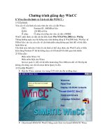
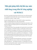
1.3 Details
Figure 1-1
• The interaction is ensured with a consistency existing across the four
automation levels:
– management level
– operator level
– control level
– field level
• In particular, the services frequently determine the economic benefit of
the involved companies (EPC, OEM, plant engineers, control cabinet
builders, system integrator and final customer) when an automation
system is to be realized.
TIA
WinCC – Examples of integrated engineering with STEP 7 Entry ID: 34995306
Version V1.0 Issue 27.04.2009 10/232
Copyright © Siemens AG Copyright 2009 All rights reserved
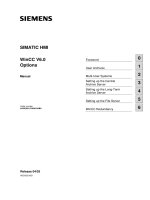
1.4 Efficiency
Figure 1-2
• The extensive I°IA/DT product range offers six system properties. The
customer also specifies general requirements for automation based on
his economic requirements. These requirements are not only supported
by the Siemens automation strategy / TIA architecture but added values
will be achieved based on the TIA system properties which an
inhomogeneous automation will not offer.
• On the left side you can see the product range which comprises the
136,000 products offered by I°IA/DT. In addition to its specific product
properties every single product contains six consistent system
properties within one application interacting in reaching a solution.
• On the right side you will find the customer's driving forces or economic
requirements which our customers and, in particular, their management
have to deal with every day. In addition to these requirements our
customers also have general requirements for their individual
automation, e.g. "openness, support of international standards" and
"scalability / modularity" to achieve investment protection or flexibility of
their automation.
• Moreover the "horizontal" and "vertical" integration gains increasing and
more elementary importance. These two requirements have played a
rather secondary role to the customers so far.
TIA
WinCC – Examples of integrated engineering with STEP 7 Entry ID: 34995306
Version V1.0 Issue 27.04.2009 11/232
Copyright © Siemens AG Copyright 2009 All rights reserved
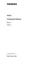
1.5 Vertical integration
Figure 1-3
The Siemens products offer consistency across all 4 levels within
automation and drive solutions which saves on costs and efforts.
• The field level contains the biggest number of components.
From the simple asynchronous motor via actuators, sensors or process
instruments, process analyzers to products which permit distributed
automation designs (I/O modules with ET 200).
• The control level contains the products which, on the one hand, control
the automation (controllers) and, on the other hand, permit the operator
to operate and monitor the automated process via operator panels
(HMI).
• The operator level provides the customer with an overview over the
entire automated system from one point in the case of complex
automation systems. Control systems (DCS) or a SCADA system
(WinCC) provide the plant manager with the desired, relevant and
condensed information in any form.
• The management level represents the interaction between the
automation system and the customer's ERP system. The connection
between the economic data and the automation data (field level) are
very important for medium-scale and large-scale production lines for
providing the plant managers with the relevant information for their
decisions.
TIA
WinCC – Examples of integrated engineering with STEP 7 Entry ID: 34995306
Version V1.0 Issue 27.04.2009 12/232
Copyright © Siemens AG Copyright 2009 All rights reserved
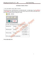
1.6 Horizontal integration
Figure 1-4
Horizontal integration or consistency means the advantage of acquiring
information from the entire production process starting with incoming goods
(discrete) via the main process (process engineering, continuous and/or
discrete) to goods output (discrete) and reverse.
The horizontal consistency provides transparency of the entire process to
avoid failures and save costs.
In addition the customer can reduce the following automation-related
expenses:
• expenses for spare parts and costs.
• same operation of the tools (e.g. engineering SW) in each of the three
horizontal phases.
• optimization of the personnel expenses as the number of software and
hardware used can be reduced to a necessary minimum.
TIA
WinCC – Examples of integrated engineering with STEP 7 Entry ID: 34995306
Version V1.0 Issue 27.04.2009 13/232
Copyright © Siemens AG Copyright 2009 All rights reserved
1.7 Added value
Figure 1-5
The portfolio for different production requirements is too big for dealing in one
workshop with all added values which the integration of WinCC provides.
• Uniform representation of all automation devices and networks in the
editors and project browsers (SIMATIC Manager, NETPRO Editor,
topology editor).
• Start of the configuration and programming tools with a double-click in
SIMATIC Manager (HMI configuration: WinCC or WinCC flexible).
• Consistent access to the process data from the management level
down to the field level.
• Direct access to STEP7 icons from out of WinCC / WinCC flexible.
• Central loading of all projects from out of the SIMATIC Manager.
• Disturbances are consistently displayed with all information from the
control to the operator level.
• Automation view (system diagnostics): Diagnosable modules signal
errors through the reporting of system error, without extensive
configuration.
• Process view (process diagnostics): Production monitoring with S7-
PDIAG and ProAgent, chronological reporting from control to HMI.
• Process data analysis with DowntimeMonitor (DTM), ProcessMonitor
(PCM), PM-Analyze or PM-Quality.
TIA
WinCC – Examples of integrated engineering with STEP 7 Entry ID: 34995306
Version V1.0 Issue 27.04.2009 14/232
Copyright © Siemens AG Copyright 2009 All rights reserved
• Remote diagnostics with WebNavigator, DataMonitor,
AlarmControlCenter (for passing on the alarms).
• Vertical integration through distributed systems (server-server
communication, CAS, etc.).
• Central user administration via SIMATIC Logon.
• Time synchronization between the levels.
• Uniform licence management (Automation Licence Manager is the
central tool for handling SIMATIC WinCC, STEP 7, etc.).
• Worldwide support and service of the entire plant is provided by one
company ().
1.8 Further reading
This list is not complete and only represents a selection of relevant
literature.
Table 1-1
Topic Title
\1\
Further
Information
\2\
Siemens I IA/DT
Customer
Support
omation.
siemens.com
Prerequisites
WinCC – Examples of integrated engineering with STEP 7 Entry ID: 34995306
Version V1.0 Issue 27.04.2009 15/232
Copyright © Siemens AG Copyright 2009 All rights reserved
2 Prerequisites
2.1 Hardware requirements
The following list contains all components used in the example:
Table 2-1
Number Module Ordering number
1 UR1 6ES7 400-1TA00-0AA0
1 PS 407 4A 6ES7 407-0DA01-0AA0
1 CPU 414-3 PN/DP 6ES7 414-3EM05-0AB0
1 IM151-3PNHFV50 6ES7 151-3BA22-0AB0
1 PM-E DC24V 6ES7 138-4CA01-0AA0
1 4DI DC24V HF 6ES7 131-4BD01-0AB0
2 2DO DC24V/0.5A HF 6ES7 132-4BB01-0AB0
1 2AI I 2/4WIRE HF 6ES7 134-4MB02-0AB0
1 2AO I HF 6ES7 135-4MB02-0AB0
1 PC with Ethernet interface ---
Note
You can also execute some of the topics dealt with (e.g. ALARM_S) with
a 300-series CPU. If you want to practice all topics discussed in this
document (e.g. Alarm_8) you will need a CPU of the 400 series.
2.2 Software requirements
The following list contains all programs used in the example:
Table 2-2
Component Note
SIMATIC WinCC V7.0 Program is used for visualization of the process.
SIMATIC STEP 7 V5.4+SP3
Program is used for program generation for control of the
process.
SIMATIC NET V7.0 Program contains the communication drivers.
2.3 Installing the software
This chapter describes the software components to be installed. It is also
important to read the descriptions, manuals and any delivery information
supplied with the products.
Prerequisites
WinCC – Examples of integrated engineering with STEP 7 Entry ID: 34995306
Version V1.0 Issue 27.04.2009 16/232
Copyright © Siemens AG Copyright 2009 All rights reserved
Installation order
To integrate WinCC in STEP 7 you have to install WinCC and also STEP 7.
For a new installation the following installation order is recommended:
1. Installation of STEP 7
2. User-defined installation of WinCC
Procedure for WinCC
1. In the start menu of the operating system open "Settings > Control Panel
> Software".
2. Select "SIMATIC WinCC V7.0" and click "Change/Delete". The WinCC
setup program opens.
3. Select whether single components or options are to be installed.
Components which have already been installed will be displayed.
4. Put the WinCC product DVD in the DVD drive when prompted. When the
start page of the DVD is opened via the autorun function, close the window
with "Finish".
5. Follow the on-screen instructions.
Prerequisites
WinCC – Examples of integrated engineering with STEP 7 Entry ID: 34995306
Version V1.0 Issue 27.04.2009 17/232
Copyright © Siemens AG Copyright 2009 All rights reserved
Table 2-3
Action Screenshot
1.
Select the following
communication
extensions during the
installation:
2.
Select the following
options during the
installation:
2.4 Further instructions for installation
You can install the required WinCC components at the same time when
you follow the described steps. However, STEP 7 can also be installed at
any time later. Single WinCC components might have to be post-installed
then.
Prerequisites
WinCC – Examples of integrated engineering with STEP 7 Entry ID: 34995306
Version V1.0 Issue 27.04.2009 18/232
Copyright © Siemens AG Copyright 2009 All rights reserved
2.5 Language settings
This documentation only contains pictures in English. It might be easier for
you to follow the examples when you select English for your configuration
tools.
• In SIMATIC Manager you select the language via "Options > Settings...
> Language".
• In WinCC you select the language via "Options > Language...".
2.6 Further reading
Bibliographic references
This list is not complete and only represents a selection of relevant
literature.
Table 2-4
Topic Title
/1/
STEP7 V5.4 Documentation
Basic Knowledge
6ES7810-4CA08-8AW0
/2/ Documentation of WinCC V7.0
omation.
siemens.com/
WW/view/en/29489481
Internet links
This list is not complete and only represents a selection of relevant
literature.
Table 2-5
Topic Title
\1\
Requirements for the
installation of STEP 7 V 5.4
omation.
siemens.com/
WW/view/en/24059047
\2\
Installation of WinCC V7.0 on
an MUI operating system if the
language set in Windows is not
English
omation.
siemens.com/
WW/view/en/32817147
\3\
Integrating an existing WinCC
project into a STEP 7 project
omation.
siemens.com/
WW/view/en/11841504
\4\
Siemens I IA/DT Customer
Support
Creating a Project
WinCC – Examples of integrated engineering with STEP 7 Entry ID: 34995306
Version V1.0 Issue 27.04.2009 19/232
Copyright © Siemens AG Copyright 2009 All rights reserved
3 Creating a Project
3.1 Introduction
Here you get an overview over the steps which are required for the creation
of an integrated WinCC project.
The instruction describes the creation of the PLC station, PC station and
networking of these components.
Creating a Project
WinCC – Examples of integrated engineering with STEP 7 Entry ID: 34995306
Version V1.0 Issue 27.04.2009 20/232
Copyright © Siemens AG Copyright 2009 All rights reserved
3.2 STEP 7 configuration
3.2.1 Inserting the PLC
Table 3-1
Step Action
1. Start the Simatic Manager and create a new project (File > New).
2.
Insert a new SIMATIC 400 station (Insert > Insert New Object > SIMATIC 400
Station).
Creating a Project
WinCC – Examples of integrated engineering with STEP 7 Entry ID: 34995306
Version V1.0 Issue 27.04.2009 21/232
Copyright © Siemens AG Copyright 2009 All rights reserved
Step Action
3. Open HW Config (Edit > Open Object) to configure your modules.
4.
Insert a rack "UR1" with the order number: 6ES7 400-1TA00 from the hardware
catalog (View > Catalog).
Creating a Project
WinCC – Examples of integrated engineering with STEP 7 Entry ID: 34995306
Version V1.0 Issue 27.04.2009 22/232
Copyright © Siemens AG Copyright 2009 All rights reserved
Step Action
5.
Insert a power supply "PS 405 4A" with the order number: 6ES7 405-0DA01-0AA0
on slot 1 of the rack from the hardware catalog (View > Catalog).
Creating a Project
WinCC – Examples of integrated engineering with STEP 7 Entry ID: 34995306
Version V1.0 Issue 27.04.2009 23/232
Copyright © Siemens AG Copyright 2009 All rights reserved
Step Action
6.
Insert a CPU "414-3 PN/DP" V5.0 with the order number: 6ES7 414-3EM05-0AB0
on slot 2 of the rack from the hardware catalog (View > Catalog).
Note:
When you select the CPU in the catalog all slots which can be used in the rack are
highlighted.
Creating a Project
WinCC – Examples of integrated engineering with STEP 7 Entry ID: 34995306
Version V1.0 Issue 27.04.2009 24/232
Copyright © Siemens AG Copyright 2009 All rights reserved
Step Action
7.
The dialog "Properties - Ethernet interface" is opened, the subnet is displayed as
"not networked". Close the dialog box with “OK”.
Creating a Project
WinCC – Examples of integrated engineering with STEP 7 Entry ID: 34995306
Version V1.0 Issue 27.04.2009 25/232
Copyright © Siemens AG Copyright 2009 All rights reserved
Step Action
8. Save and compile HW Config (Station > Save and compile).