Elantra(AD) 2020, automatic transaxle, 2 0 MPI
Bạn đang xem bản rút gọn của tài liệu. Xem và tải ngay bản đầy đủ của tài liệu tại đây (1 MB, 24 trang )
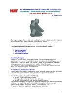
AUTOMATIC TRANSAXLE for ELANTRA (AD) 2020, 2.0 mpi
SPECIFICATIONS
Item
Specifications
Transaxle type
A6MF1-2
Engine type
Gasoline 2.0 MPI, FFV
Torque converter type
3-element, 1-stage, 2-phase type
Torque converter size
Ø236 mm (9.2913 in)
Oil pump system
Mechanical internal gear pump
Clutch: 2EA
Friction elements
Brake: 3EA
OWC: 1EA
Planetary gear
Gear ratio
3EA
1st
4.400
2nd
2.726
3rd
1.834
4th
1.392
5th
1.000
6th
0.774
Reverse
3.440
Final gear ratio
3.270
Fluid pressure balance piston
2EA
Accumulator
4EA
Solenoid valve
7EA (VFS:6EA, ON/OFF:1EA)
Shift lever position
4 Range (P,R,N,D)
Oil filter
1EA
VFS: Variable Force Solenoid
Sensors
Input Speed Sensor
▷ Type : Hall effect sensor
▷ Specifications
Items
Specifications
Operation condition (°C)°F
(-40 ~ 150) -40 ~ 302
Output voltage (V)
High
1.18 ~ 1.68
Low
0.59 ~ 0.84
Output Speed Sensor
▷ Type : Hall effect sensor
▷ Specifications
Items
Specifications
Operation condition (°C)°F
(-40 ~ 150) -40 ~ 302
Output voltage (V)
High
1.18 ~ 1.68
Low
0.59 ~ 0.84
Oil Temperature Sensor
▷ Type : Negative Thermal Coefficient (NTC)
▷ Specifications
Temp.[(°C)°F]
Resistance (Ω)
Min
Max
(-40) -40
48153
45301
51006
(-20) -4.0
15614
14785
16443
(0) 32.0
5887
5605
6168
(20) 68.0
2510.6
2401.9
2619.3
(40) 104.0
1199.6
1152.4
1246.7
(60) 140.0
612.3
590.3
634.2
(80) 176.0
329.5
318.7
340.3
(100) 212.0
186
180.4
191.6
(120) 248.0
109.7
106.1
113.2
(140) 284.0
67.16
64.82
69.5
(150) 302.0
53.24
51.32
55.16
Inhibitor Switch
▷ Type : Combination of output signals from 4 terminals
▷ Specifications
Items
Specifications
Power supply (V)
12
Output type
Combination of output signals
Solenoid Valves
ON/OFF Solenoid Valve(SS-A)
▷ Control type : Normally low type
Shape
Items
Specifications
Control voltage [V]
9 ~ 16
Supply pressure [kpa (kgf/cm², psi)]
490.33 (5.0, 71.12)
Control pressure [kpa (kgf/cm², psi)]
0 ~ 490.33 (0 ~ 5.0, 0 ~ 71.12)
Internal resistance(Ω)
10 ~ 11
Items
Specifications
Control current [mA]
0 ~ 850
Supply pressure [kpa (kgf/cm², psi)]
539.36 (5.5, 78.23)
Control pressure [kpa (kgf/cm², psi)]
0 ~ 519.75 (0 ~ 5.3, 0 ~ 75.38)
Internal resistance(Ω)
4.8 ~ 5.4
Clutch/Brake control VFS[T/CON]
▷ Control type : Normally low type
Shape
Line Pressure Control VFS[Line pressure]
▷ Control type : Normally high type
Shape
Items
Specifications
Control current [mA]
0 ~ 850
Supply pressure [kpa (kgf/cm², psi)]
539.36 (5.5, 78.23)
Control pressure [kpa (kgf/cm², psi)]
0 ~ 519.75 (0 ~ 5.3, 0 ~ 75.38)
Internal resistance(Ω)
4.8 ~ 5.4
Items
Specifications
Control current [mA]
0 ~ 1100
Supply pressure [kpa (kgf/cm², psi)]
1569.06 (16, 227.57)
Control pressure [kpa (kgf/cm², psi)]
0 ~ 1569.06 (0 ~ 16, 0 ~ 227.57)
Internal resistance(Ω)
5.0 ~ 5.6
Items
Specifications
Control current [mA]
0 ~ 1100
Supply pressure [kpa (kgf/cm², psi)]
1569.06 (16, 227.57)
Control pressure [kpa (kgf/cm², psi)]
0 ~ 1569.06 (0 ~ 16, 0 ~ 227.57)
Internal resistance(Ω)
5.0 ~ 5.6
Clutch/Brake control VFS[26/B,35R/C]
▷ Control type : Normally low type
Shape
Clutch/Brake control VFS[UD/B, OD/C]
▷ Control Type : Normally high type
Shape
Solenoid Valve Operation Table
UD
OD & LD
35 R
26B
SS - A
P
●
●
N
●
●
1 st
Δ
2 nd
●
3 rd
●
Δ
●
●
4 th
5 th
●
6 th
●
REV
●
●
●
●
●
● : Connected status
Δ : Connected at vehicle speed above 8km/h
Tightening Torques
Item
N.m
kgf.m
lb-ft
Shift cable bracket mounting bolt
14.7 ~ 21.6
1.5 ~ 2.2
10.8 ~ 15.9
Fixing nut of shift cable in the manual lever
9.8 ~ 13.7
1.0 ~ 1.4
7.2 ~ 10.1
Automatic transaxle upper mounting bolt
(TM=>Eng)
42.2 ~ 53.9
4.3 ~ 5.5
31.1 ~ 39.8
Automatic transaxle mounting bracket bolt
88.3 ~ 107.9
9.0 ~ 11.0
65.1 ~ 79.6
Automatic transaxle support bracket
mounting bolt
58.9 ~ 78.5
6.0 ~ 8.0
43.4 ~ 57.8
Torque converter mounting bolt
45.1 ~ 52.0
4.6 ~ 5.3
33.3 ~ 38.3
Automatic transaxle lower mounting bolt
(Eng=>TM)
42.2 ~ 48.1
4.3 ~ 4.9
31.1 ~ 35.4
42.2 ~ 53.9
4.3 ~ 5.5
31.1 ~ 39.8
TCM mounting nut
9.8 ~ 11.8
1.0 ~ 1.2
7.2 ~ 8.7
Input shaft speed sensor mounting bolt
9.8 ~ 11.8
1.0 ~ 1.2
7.2 ~ 8.7
Output shaft speed sensor mounting bolt
9.8 ~ 11.8
1.0 ~ 1.2
7.2 ~ 8.7
Shift lever assembly bolt
8.8 ~ 13.7
0.9 ~ 1.4
9.4 ~ 10.8
Inhibitor switch mounting bolt
9.8 ~ 11.8
1.0 ~ 1.2
7.2 ~ 8.7
Valve body cover mounting bolt
11.8 ~ 13.7
1.2 ~ 1.4
8.7 ~ 10.1
ATF drain plug
33.3 ~ 43.1
3.4 ~ 4.4
24.6 ~ 31.8
Starter mounting bolt
49.0 ~ 63.7
5.0 ~ 6.5
36.2 ~ 47.0
LUBRICANTS
Fluid
ATF Grade
Recommended
Allowed
ATF SP-Ⅳ
SK ATF SP-Ⅳ, MICHANG ATF SP-Ⅳ,NOCA ATF SP-Ⅳ,
Hyundai Genuine ATF SP-Ⅳ
ATF Quantity
6.7L(1.77 U.S gal., 7.08 U.S.qt., 5.90 Imp.qt.)
Sealant
Item
Specified sealant
Torque converter housing
LOCTITE FMD-546
TROUBLESHOOTING
Trouble symptom
Shift delay
Vibration of the vehicle
when shifting
Fixed gear (shift
Suspect area
Remedy
Damaged clutch / brake
Replace the brake or clutch.
Faulty hydraulic control
Inspect the solenoid valve.
Faulty hydraulic supply
Check the fluid level.
Not performed TCM learning
TCM learning is required.
Damaged clutch / brake
Replace the brake or clutch.
Not performed TCM learning
TCM learning is required.
Faulty hydraulic control
Inspect the solenoid valve.
Faulty hydraulic supply
Check the fluid level.
Faulty hydraulic control
Inspect the solenoid valve.
impossible)
limited gear (shift
possible)
Poor acceleration
Replace the solenoid valve or valve body.
Faulty harness & connector
connection
Check the harness & connector of transaxle.
Faulty TCM
Replace the TCM.
Faulty CAN Communication
Inspect the CAN communication line.
Faulty inhibitor switch
Inspect the inhibitor switch.
Faulty input & output speed
sensor
Inspect the input & output speed sensor.
Faulty harness & connector
connection
Check the harness & connector of transaxle.
Faulty hydraulic control
Inspect the solenoid valve.
Faulty hydraulic supply
Check the fluid level.
Faulty oil pump
Replace the oil pump.
COMPONENTS LOCATION(1)
1. Automatic transaxle assembly
2. ATF cooler tube
3. Ground line
4. Shift cable mounting bracket
5. Shift cable
6. Inhibitor switch & manual control lever
7. Mounting bracket cover
8. Support bracket mounting bolt
9. Automatic transaxle mounting bracket
10. ATF cooler hose
11. ATF cooler & radiator
COMPONENTS LOCATION(2)
1. Automatic transaxle assembly
2. Subframe assembly
3. Roll rod support bracket
4. Roll rod bracket
DESCRIPTION HYDRAULIC SYSTEM
• The oil pump is powered by the engine. ATF passes through the oil filter and gets distributed along the oil
channels.
• The oil becomes highly pressurized as it exits the oil pump and passes through the line pressure valve before
being fed to the clutch & brake control valve, clutch, and brakes.
• TCM controls the hydraulic pressure using solenoid valves and controls clutch and brake operations.
Flow of the hydraulic system
Rate this Document
COMPONENTS LOCATION
1. Automatic transaxle
2. Oil filter
3. Mechanical oil pump
4. Converter housing
5. Torque converter
DESCRIPTION MOP
• The oil pump is built-in as a single unit with the 26 Brake chamber.
• Rotation of the pump builds the hydraulic pressure needed for the lubrication of the various parts of the transaxle
and operation of the clutch and brakes.
• The oil also circulates through the torque converter and the cooler.
Operation flow of the mechanical oil pump
COMPONENTS
1. Housing - Oil pump
2. Cover - Oil pump
3. Gear - Oil pump drive
4. Gear - Oil pump driven
5. Shaft - Reaction
6. Oil - Seal
7. Sleeve
8. Bearing - Housing
9. Cap - Sealing
10. Needle roller bearing
11. Bolt
12. Snap ring - Housing
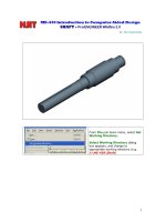
REMOVAL
1. Remove the automatic transaxle.
(Refer to Automatic Transaxle System - "Automatic Transaxle")
2. Loosen the drain plug (A) and wait for at least until the oil is drained sufficiently, and then reinstall the drain plug together w
Tightening torque :
34.3 - 44.1N.m (3.5 - 4.5 kgf.m, 25.3 - 32.5 lb-ft)
• If reinstall the drain plug, replace the gasket (A) with a new one.
3. Remove the torque converter (A) from torque converter housing.
4. Loosen the bolts and then removing the bracket (A).
Tightening torque :
9.8 - 11.8 N.m (1.0 - 1.2 kgf.m, 7.2 - 8.7 lb-ft)
5. Loosen the torque converter housing bolts.
Tightening torque :
28.4 - 35.3 N.m (2.9 - 3.6 kgf.m, 20.9 - 26.0 lb-ft)
[Torque converter side]
[Transaxle side]
6. Remove the torque converter housing (A).
7. Loosen the bolts and then removing the mechanical oil pump (A).
Tightening torque :
19.6 - 25.5 N.m (2.0 - 2.6 kgf.m, 14.5 - 18.8 lb-ft)
INSTALLATION
1. To install, reverse the removal procedures.
2. Injection the ATF.
(Refer to Hydraulic System - "Fluid")
COMPONENTS LOCATION FLUID
1. Automatic transaxle
2. Drain plug gasket
3. Drain plug
4. ATF level check plug
5. ATF level check plug gasket
6. ATF injection plug O-Ring
7. ATF injection plug (Eyebolt)
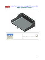
SERVICE ADJUSTMENT PROCEDURE
ATF level Check
• A check of ATF level is not normally required during scheduled services. If an ATF leak is found, perform the ATF level ch
completed.
• When checking the oil level, be careful not to enter dust, foreign matters, etc. from fill hole.
1. Remove the air cleaner assembly and air duct.
(Refer to Engine Mechanical System - "Air cleaner")
2. Remove the eyebolt (A).
3. Add ATF SP-IV 700cc to the ATF injection hole (A).
4. Install the air cleaner assembly and air duct.
(Refer to Engine Mechanical System - "Air cleaner")
5. Start the engine.
(Don’t step on brake and accelerator simultaneously.)
6. Confirm that the temperature of the automatic transaxle oil temperature sensor is 50 - 60°C (122 - 140°F) with the GDS.
7. Shift the select lever slowly from “P” to “D”, then “D” to “P” and repeat one more at idle.
• Pause at each gear position more than 2 seconds.
8. Lift the vehicle, then remove the under cover.
(Refer to Engine Mechanical System - "Engine room under cover")
9. Remove the ATF level check plug (A) from the valve body cover.
• At this time, the vehicle must be at a level state.
10. If the ATF flows out of the overflow plug in thin steady stream, the ATF level is correct.
Then finish the procedure and tighten the ATF level check plug.
Oil level check (excess or shortage) method
• Excess: Drain quantity exceed 900cc for tow minutes.{50 - 60°C (122 - 140°F)}
• Shortage: No ATF flows out of the overflow plug.
• Replace the gasket before reinstalling the ATF level check plug.
• Turn the oil level check plug clockwise until it is set.
• If there is no damage at the automatic transaxle and the ATF cooler, the ATF cooler hose, transaxle case, valve bod
must drip out after performing above 1 to 7 procedures. After performing above 1 to 7 procedures, if the oil doesn’t d
transaxle assembly.
11. Install the under cover.
(Refer to Engine Mechanical System - "Engine room under cover")
12. Put down the vehicle with the lift and then tighten the eyebolt.
• Replace the gasket (A) before reinstalling the eyebolt.
REPLACEMENT
ATF of 6 speed automatic transaxle doesn’t be replaced. But, if the vehicle is severe use or business use, replace ATF every
Severe usage is defined as
• Driving in rough road (Bumpy, Gravel, Snowy, Unpaved road, etc).
• Driving in mountain road, ascent/descent.
• Repetition of short distance driving.
• More than 50% operation in heavy city traffic during hot weather above 32°C(89.6°F) .
• Police, Taxi, Commercial type operation or trailer towing, etc.
1. Lift the vehicle, then remove the under cover.
(Refer to Engine Mechanical System - "Engine room under cover")
2. Remove the drain plug (A) and reinstall the drain plug after draining ATF totally.
• Replace the gasket before reinstalling the drain plug.
Drain plug tightening torque:
33.3 - 43.1 N.m (3.4 - 4.4 kgf.m, 24.6 - 31.8 lb-ft)
3. Put down the vehicle with the lift and then remove the eyebolt (A).
4. Fill the ATF about 5 liters to the injection hole (A).
5. Check the ATF level.
(Refer to Automatic Transaxle System-" Automatic Transaxle Fluid(ATF)")
6. Then finish check the ATF level procedure and install the under cover.
(Refer to Engine Mechanical System - "Engine room under cover")
7 Put down the vehicle with the lift and then tighten the eyebolt.
.
VALVE BODY SYSTEM
1. Automatic transaxle
2. Input/Output speed sensor
3. Valve body assembly
4. Solenoid valve connector module
5. Valve body cover
6. Gasket
DESCRIPTION
The valve body is essential to automatic transaxle control and consists of various valves used to control the oil feed
from the oil pump. Specifically, these valves consist of pressure regulator valves, oil redirection valves, shift valves,
and manual valves.
The body also features electronic solenoid valves that ensure smooth gear changes.
1. Solenoid valve support bracket
2. Solenoid valve support bracket (Directly solenoid)
3. Line Pressure Control Solenoid Valve
4. Torque Convert Control Solenoid Valve (T/CON)
5. ON/OFF solenoid valve
6. Overdrive Clutch Control Solenoid Valve (OD/C)
7. Underdrive Brake Control Solenoid Valve (UD/B)
8. 35R Clutch Control Solenoid Valve (35R/C)
9. 26 Brake Control Solenoid Valve (26B)
10. LR/B pressure flow hole
11. UD/B pressure flow hole
12. Accumulator
REPLACEMENT
If necessary replace the valve body or solenoid valves, hydraulic adjustment is needed, replace the automatic transaxle ass
After the automatic transaxle assembly exchange, input the hydraulic calibration information of TCM.
1. Perform the oil pressure characteristics input procedure.
• Oil pressure characteristics(bar code) location
• Oil-pressure characteristics input
(Transmision exchange)
DESCRIPTION CLUTCH & BRAKE
The 6-speed automatic transaxle consists of an overdrive clutch (OD/C), a one-way clutch (OWC), a lower and reverse brak
brake (26/B), and a 35R clutch (35R/C). These clutches and brakes are operated by controlling the hydraulic pressure.
COMPONENTS LOCATION
1. Overdrive clutch (OD/C)
2. One way clutch (OWC)
3. Low & Reverse brake (LR/B)
4. Underdrive brake (UD/B)
5. 26 brake(26/B)
6. 35R clutch (35R/C)
7. Damper clutch (D/C)
POWER FLOW CHART
P,N
UD/B
LR/B
●
26/B
35R/C
OD/C
OWC
▣ Direction of Rotation
▶Lower & Reverse Brake (LR/B) Activation → Overdrive (O/D) Hub Lock → Mid & Rear P/C Lock
▶Input Shaft Rotation → Rear Sun Gear Rotation → Rear Inner Pinion Rotation (Reverse) → Rear Outer Pinion
Rotation → Rear Annulus Gear Rotation → Front Annulus Gear Rotation → Front Pinion Rotation → Front Sun Gear
Rotation (Reverse) → Underdrive (U/D) Hub Rotation (Reverse)
▶Input shaft rotation → Overdrive Clutch (OD/C) Retainer Rotation
▶Input shaft rotation → 35R Clutch Rotation
R
UD/B
LR/B
26/B
35R/C
●
OD/C
OWC
●
▣ Power Delivery Route
▶ Middle carrier locked and middle sun gear in rotation
▶ Rotating the middle planetary gear's sun gear while its carrier is locked in place slows down and reverse rotates the
annulus gear (front carrier), resulting in power transfer to the front carrier.
▶ The rear planetary gear's rear and front annulus gears rotate at a reduced rate, resulting in reverse, zero load
rotation of the front planetary gear's front sun gear.
D1
UD/B
LR/B
●
(°)
26/B
35R/C
OD/C
OWC
●
▣ Power Delivery Route
▶ Front sun gear and middle & rear carrier locked and rear sun gear in constant rotation
▶ When the rear sun gear is rotated, power is reduced at the rear planetary gear and then delivered to the rear and
front annulus gears. The power is then reduced again at the front planetary gear, whose sun gear is locked in place,
and then delivered to the front carrier.
▶ Here, the middle annulus gear, which comprises of a single unit with the front carrier, rotates and results in reverse,
zero load rotation of the middle sun gear.
UD/B
D2
LR/B
26/B
●
35R/C
●
▣ Power Delivery Route
▶ Front sun gear and middle sun gear locked and rear sun gear in constant rotation
▶ Rotating the rear sun gear delivers power to the rear & front annulus gears, and reaction from the front carrier and
the middle annulus gear, to which the sun gear is attached, transfers to the middle and rear carriers, resulting in
power equilibrium and power transfer to the front carrier.
D3
UD/B
●
LR/B
26/B
35R/C
●
OD/C
OWC
▣ Power Delivery Route
▶ Front sun gear locked and middle and rear sun gears in rotation
▶ Rotating the middle sun gear and the rear sun gear transfers power to the rear and front annulus gears, and
reaction from the front carrier and the middle annulus gear, to which the sun gear is attached, transfers to the middle
and rear carriers, resulting in power equilibrium and power transfer to the front carrier.
D4
UD/B
LR/B
26/B
35R/C
OD/C
●
OWC
●
▣ Power Delivery Route
▶ Front sun gear locked and rear carrier and rear sun gears in rotation
▶ Activation of the overdrive clutch (OD/C) synchronizes the rear planetary gear's carrier and sun gears. The 1:1
rotation ratio passes through the rear and front annulus gears and reaches the front planetary gear's front carrier, to
which the sun gear is attached.
▶ Here, the middle planetary gear's middle sun gear rotates at a faster rate in the normal direction and at zero load
due to the actions of the reduced annulus gear and the carrier having a 1:1 rotation ratio.
D5
UD/B
LR/B
26/B
35R/C
OD/C
●
●
OWC
▣ Power Delivery Route
▶ Middle and rear carriers, middle sun gear, and rear sun gear in rotation
▶ The middle planetary gear's middle carrier and sun gear rotate simultaneously, resulting in the 1:1 rotation ratio
being transferred to the middle annulus gear (front carrier).
▶ Here, the rear planetary gear rotates in a 1:1 rotation ratio, as it would when the 4th gear is engaged; however, the
front planetary gear remains unrestrained and the front sun gear rotates in the normal direction, at a zero load, and at
a rotation ratio of 1:1.
D6
UD/B
LR/B
26/B
●
35R/C
OD/C
OWC
●
▣ Power Delivery Route
▶ Middle carrier in rotation and middle sun gear locked
▶ When the middle planetary gear's sun gear is locked in place and the train's carrier's allowed to rotate, the middle
annulus gear increases its rate of rotation and transfers power to the front carrier.
▶ Here, the rear planetary gear maintains a 1:1 rotation ratio as it would when 4th or 5th gear is engaged; however,
the front planetary gear remains unrestrained and the front sun gear rotates at a faster rate in the normal direction
and at zero load.