Lab 7.1.9a Introduction to Fluke Network Inspector
Bạn đang xem bản rút gọn của tài liệu. Xem và tải ngay bản đầy đủ của tài liệu tại đây (329.8 KB, 12 trang )
Lab 7.1.9a Introduction to Fluke Network Inspector
Objective
This lab is a tutorial demonstrating how to use the Fluke Networks Network Inspector (NI) to discover
and analyze network devices within a broadcast domain. This lab will demonstrate the key features
of the tool that can be incorporated into various troubleshooting efforts in the remaining labs.
Background / Preparation
The Network Inspector software can distinguish workstations, servers, network printers, switches,
and managed hubs, if they have been assigned a network address.
Options for conducting this lab.
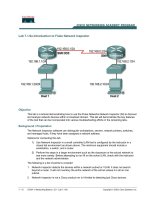
1) Use Network Inspector in a small controlled LAN that is configured by the instructor in a
closed lab environment as shown above. The minimum equipment should include a
workstation, a switch, and a router.
2) Perform the steps in a larger environment such as the classroom or the school network to
see more variety. Before attempting to run NI on the school LAN, check with the instructor
and the network administrator.
The following is a list of points to consider:
1. Network Inspector detects the devices within a network subnet or VLAN. It does not search
beyond a router. It will not inventory the entire network of the school unless it is all on one
subnet.
2. Network Inspector is not a Cisco product nor is it limited to detecting just Cisco devices.
1 - 12 CCNA 1: Networking Basics v 3.0 - Lab 7.1.9a Copyright 2003, Cisco Systems, Inc.
3. Network Inspector is a detection tool, but it is not a configuration tool. It cannot be used to
reconfigure any devices.
The output in this lab is representative only, and output will vary depending on the number of
devices, device MAC addresses, device hostnames, and which LAN is joined.
This lab introduces the Fluke Networks Network Inspector software, which may be useful in later
troubleshooting labs and in the field. While the Network Inspector software is a valuable part of the
Academy program, it is also representative of features available on other products in the market.
At least one host must have the Network Inspector software installed. If the lab is done in pairs,
having the software installed on both machines means that each person can run the lab steps. Be
sure to select both the Network Inspector and the Network Inspector Agent during installation.
The Console can be anywhere that has a valid IP path and security to allow the connection to an
Agent. In fact, it might be an interesting exercise to have the Console reach across the serial link to
load the database from the other Agent. The student can have the Console reading from a different
database than the one that is currently in use by the Agent on the same PC.
Step 1 Configure the lab or attach the workstation to the school LAN
Option 1. If the closed lab environment is selected, cable the equipment as shown above and load
the configuration files into the appropriate routers. These files might already be preloaded.
If not, obtain them from the instructor. These files should support the IP addressing
scheme as shown in the figure above and the table below.
Configure the workstation according to the specifications in the table below.
Host #1 Host #2
IP Address: 192.168.1.10 IP Address: 192.168.2.10
Subnet mask: 255.255.255.0 Subnet mask: 255.255.255.0
Default Gateway: 192.168.1.1 Default Gateway: 192.168.2.1
Since the software discovers devices on the network, the more devices the better the demonstration.
If available, add additional hosts to both LANs.
Option 2. If option 2, connect to school LAN, is selected, simply connect the workstation, with
Network Inspector or Protocol Expert installed, directly to a classroom switch or to a data
jack connected to the school LAN.
Step 2 Start Network Inspector and the Agent
From the Start menu, launch the Network
Inspector Console.
Click on the Agent button at the left end of
the toolbar so that the Agent can be started.
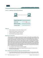
If necessary, select the Agent tab in the window, then click on the Start button and watch the Status
box until it shows that the Agent is running as in the figure below. This process may take several
minutes to start.
2 - 12 CCNA 1: Networking Basics v 3.0 - Lab 7.1.9a Copyright 2003, Cisco Systems, Inc.
Notice the Agent status on the bottom of the Console window. Look closely and notice that the Agent
has been running since 9:57 PM in the second graphic captured below that is in Step 3.
Use the Close button in the lower-right corner of the Agent window to send the Agent away. In some
versions, this may be a Hide button. Do not use the Stop button or the discovery process will cease.
Step 3 Allow network discovery to occur
The Network Inspector software is designed to quietly, both passively and actively, collect network
data. As such it takes time for devices to appear. This small network should be discovered in a
minute or two. Active collection of statistical data is delayed for the first 10 minutes. An actual
production network might take 30 minutes or more before most data is discovered.
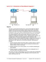
After a few minutes, the Console window should start showing information about the network. In the
following example, two additional workstations were added.
Note: Entries from previous sessions may be seen. It will take a few minutes for the entries
to match the network. In the Agent window, under the Database/Address tab, there is a
checkbox for Overwrite. If that box is checked, the current database content is discarded
and a fresh data set is loaded as it is discovered when the Agent starts. Otherwise, any new
data is integrated with the existing database as it is discovered.
3 - 12 CCNA 1: Networking Basics v 3.0 - Lab 7.1.9a Copyright 2003, Cisco Systems, Inc.
Notice the hostnames, which areM450, SanJose1 and Thunder, in the example above. PC
hostnames will be different in student output. Also notice the IP addresses and MAC addresses for
each discovered device. It should be obvious that both SanJose1 and SanJose2 have two IP
addresses assigned to the LAN interface.
Notice that NI does not investigate beyond the router interface. It collects information only on the
devices that share the same broadcast domain as the computer NIC.
Step 4 Investigate device properties
Double click on the router device name and look over the available Device Properties. Remember
that results will depend on the devices included in the LANs subnet.
The Overview tab in the above graphic shows IP addresses, the IPX address, the IPX networks
attached, the IPX data frame used (802.3 above), and the MAC address. Notice that the OUI has
been converted to identify the manufacturer in the above example.
The closest switches will only appear if Network Inspector has been provided with a valid SNMP
Community String for them.
The Problems tab reveals one of the IP addresses is duplicated within the network. This occurs if
the student configured an optional host as defined in Step 1. The red ball to the left of the
Description indicates a problem.
4 - 12 CCNA 1: Networking Basics v 3.0 - Lab 7.1.9a Copyright 2003, Cisco Systems, Inc.
The Services tab reveals the IP and IPX Services running on the routers.
The IP Services example in the graphic above reveals that the IP HTTP Server service has been
turned on. This means the router can be accessed via a Web browser.
The IPX Services shows the IPX Network ID (30), the Node address (MAC), the frame type, and the
fact that IPX RIP is running.
The bottom third of the window shows the information that would have been revealed if the device
had been a Novell Server. A multi-homed server, which is one with more than one NIC (connection)
in separate networks, is working as a router or bridge.
The MIB SNMP tab reveals SNMP information as well as the router IOS information.
5 - 12 CCNA 1: Networking Basics v 3.0 - Lab 7.1.9a Copyright 2003, Cisco Systems, Inc.