Basic Concepts part 2
Bạn đang xem bản rút gọn của tài liệu. Xem và tải ngay bản đầy đủ của tài liệu tại đây (25.55 KB, 8 trang )
[ Team LiB ]
3.2 Data Types
This section discusses the data types used in Verilog.
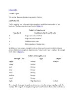
3.2.1 Value Set
Verilog supports four values and eight strengths to model the functionality of real
hardware. The four value levels are listed in Table 3-1
.
Table 3-1. Value Levels
Value Level Condition in Hardware Circuits
0 Logic zero, false condition
1 Logic one, true condition
x Unknown logic value
z High impedance, floating state
In addition to logic values, strength levels are often used to resolve conflicts between
drivers of different strengths in digital circuits. Value levels 0 and 1 can have the strength
levels listed in Table 3-2
.
Table 3-2. Strength Levels
Strength Level Type Degree
supply Driving strongest
strong Driving
pull Driving
large Storage
weak Driving
medium Storage
small Storage
highz High Impedance weakest
If two signals of unequal strengths are driven on a wire, the stronger signal prevails. For
example, if two signals of strength strong1 and weak0 contend, the result is resolved as a
strong1. If two signals of equal strengths are driven on a wire, the result is unknown. If
two signals of strength strong1 and strong0 conflict, the result is an x. Strength levels are
particularly useful for accurate modeling of signal contention, MOS devices, dynamic
MOS, and other low-level devices. Only trireg nets can have storage strengths large,
medium, and small. Detailed information about strength modeling is provided in
Appendix A
, Strength Modeling and Advanced Net Definitions.
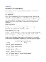
3.2.2 Nets
Nets represent connections between hardware elements. Just as in real circuits, nets have
values continuously driven on them by the outputs of devices that they are connected to.
In Figure 3-1
net a is connected to the output of and gate g1. Net a will continuously
assume the value computed at the output of gate g1, which is b & c.
Figure 3-1. Example of Nets
Nets are declared primarily with the keyword wire. Nets are one-bit values by default
unless they are declared explicitly as vectors. The terms wire and net are often used
interchangeably. The default value of a net is z (except the trireg net, which defaults to x
). Nets get the output value of their drivers. If a net has no driver, it gets the value z.
wire a; // Declare net a for the above circuit
wire b,c; // Declare two wires b,c for the above circuit
wire d = 1'b0; // Net d is fixed to logic value 0 at declaration.
Note that net is not a keyword but represents a class of data types such as wire, wand,
wor, tri, triand, trior, trireg, etc. The wire declaration is used most frequently. Other net
declarations are discussed in Appendix A
, Strength Modeling and Advanced Net
Definitions.
3.2.3 Registers
Registers represent data storage elements. Registers retain value until another value is
placed onto them. Do not confuse the term registers in Verilog with hardware registers
built from edge-triggered flipflops in real circuits. In Verilog, the term register merely
means a variable that can hold a value. Unlike a net, a register does not need a driver.
Verilog registers do not need a clock as hardware registers do. Values of registers can be
changed anytime in a simulation by assigning a new value to the register.
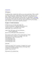
Register data types are commonly declared by the keyword reg. The default value for a
reg data type is x. An example of how registers are used is shown Example 3-1
.
Example 3-1 Example of Register
reg reset; // declare a variable reset that can hold its value
initial // this construct will be discussed later
begin
reset = 1'b1; //initialize reset to 1 to reset the digital circuit.
#100 reset = 1'b0; // after 100 time units reset is deasserted.
end
Registers can also be declared as signed variables. Such registers can be used for signed
arithmetic. Example 3-2
shows the declaration of a signed register.
Example 3-2 Signed Register Declaration
reg signed [63:0] m; // 64 bit signed value
integer i; // 32 bit signed value
3.2.4 Vectors
Nets or reg data types can be declared as vectors (multiple bit widths). If bit width is not
specified, the default is scalar (1-bit).
wire a; // scalar net variable, default
wire [7:0] bus; // 8-bit bus
wire [31:0] busA,busB,busC; // 3 buses of 32-bit width.
reg clock; // scalar register, default
reg [0:40] virtual_addr; // Vector register, virtual address 41 bits wide
Vectors can be declared at [high# : low#] or [low# : high#], but the left number in the
squared brackets is always the most significant bit of the vector. In the example shown
above, bit 0 is the most significant bit of vector virtual_addr.
Vector Part Select
For the vector declarations shown above, it is possible to address bits or parts of vectors.
busA[7] // bit # 7 of vector busA
bus[2:0] // Three least significant bits of vector bus,
// using bus[0:2] is illegal because the significant bit should
// always be on the left of a range specification
virtual_addr[0:1] // Two most significant bits of vector virtual_addr
Variable Vector Part Select
Another ability provided in Verilog HDl is to have variable part selects of a vector. This
allows part selects to be put in for loops to select various parts of the vector. There are
two special part-select operators:
[<starting_bit>+:width] - part-select increments from starting bit
[<starting_bit>-:width] - part-select decrements from starting bit
The starting bit of the part select can be varied, but the width has to be constant. The
following example shows the use of variable vector part select:
reg [255:0] data1; //Little endian notation
reg [0:255] data2; //Big endian notation
reg [7:0] byte;
//Using a variable part select, one can choose parts
byte = data1[31-:8]; //starting bit = 31, width =8 => data[31:24]
byte = data1[24+:8]; //starting bit = 24, width =8 => data[31:24]
byte = data2[31-:8]; //starting bit = 31, width =8 => data[24:31]
byte = data2[24+:8]; //starting bit = 24, width =8 => data[24:31]
//The starting bit can also be a variable. The width has
//to be constant. Therefore, one can use the variable part select
//in a loop to select all bytes of the vector.
for (j=0; j<=31; j=j+1)
byte = data1[(j*8)+:8]; //Sequence is [7:0], [15:8]... [255:248]
//Can initialize a part of the vector
data1[(byteNum*8)+:8] = 8'b0; //If byteNum = 1, clear 8 bits [15:8]
3.2.5 Integer , Real, and Time Register Data Types
Integer, real, and time register data types are supported in Verilog.
Integer
An integer is a general purpose register data type used for manipulating quantities.
Integers are declared by the keyword integer. Although it is possible to use reg as a
general-purpose variable, it is more convenient to declare an integer variable for purposes
such as counting. The default width for an integer is the host-machine word size, which is
implementation-specific but is at least 32 bits. Registers declared as data type reg store
values as unsigned quantities, whereas integers store values as signed quantities.
integer counter; // general purpose variable used as a counter.
initial
counter = -1; // A negative one is stored in the counter
Real
Real number constants and real register data types are declared with the keyword real.
They can be specified in decimal notation (e.g., 3.14) or in scientific notation (e.g., 3e6,
which is 3 x 10
6
). Real numbers cannot have a range declaration, and their default value
is 0. When a real value is assigned to an integer, the real number is rounded off to the
nearest integer.
real delta; // Define a real variable called delta
initial
begin
delta = 4e10; // delta is assigned in scientific notation
delta = 2.13; // delta is assigned a value 2.13
end
integer i; // Define an integer i
initial
i = delta; // i gets the value 2 (rounded value of 2.13)
Time
Verilog simulation is done with respect to simulation time. A special time register data
type is used in Verilog to store simulation time. A time variable is declared with the
keyword time. The width for time register data types is implementation-specific but is at
least 64 bits.The system function $time is invoked to get the current simulation time.
time save_sim_time; // Define a time variable save_sim_time
initial
save_sim_time = $time; // Save the current simulation time
Simulation time is measured in terms of simulation seconds. The unit is denoted by s, the
same as real time. However, the relationship between real time in the digital circuit and
simulation time is left to the user. This is discussed in detail in Section 9.4
, Time Scales.
3.2.6 Arrays
Arrays are allowed in Verilog for reg, integer, time, real, realtime and vector register data