Tài liệu Hierarchical Modeling Concepts part 2 ppt
Bạn đang xem bản rút gọn của tài liệu. Xem và tải ngay bản đầy đủ của tài liệu tại đây (22.33 KB, 8 trang )
[ Team LiB ]
2.4 Instances
A module provides a template from which you can create actual objects. When a module
is invoked, Verilog creates a unique object from the template. Each object has its own
name, variables, parameters, and I/O interface. The process of creating objects from a
module template is called instantiation, and the objects are called instances. In Example
2-1, the top-level block creates four instances from the T-flipflop (T_FF) template. Each
T_FF instantiates a D_FF and an inverter gate. Each instance must be given a unique
name. Note that // is used to denote single-line comments.
Example 2-1 Module Instantiation
// Define the top-level module called ripple carry
// counter. It instantiates 4 T-flipflops. Interconnections are
// shown in Section 2.2, 4-bit Ripple Carry Counter.
module ripple_carry_counter(q, clk, reset);
output [3:0] q; //I/O signals and vector declarations
//will be explained later.
input clk, reset; //I/O signals will be explained later.
//Four instances of the module T_FF are created. Each has a unique
//name.Each instance is passed a set of signals. Notice, that
//each instance is a copy of the module T_FF.
T_FF tff0(q[0],clk, reset);
T_FF tff1(q[1],q[0], reset);
T_FF tff2(q[2],q[1], reset);
T_FF tff3(q[3],q[2], reset);
endmodule
// Define the module T_FF. It instantiates a D-flipflop. We assumed
// that module D-flipflop is defined elsewhere in the design. Refer
// to Figure 2-4 for interconnections.
module T_FF(q, clk, reset);
//Declarations to be explained later
output q;
input clk, reset;
wire d;
D_FF dff0(q, d, clk, reset); // Instantiate D_FF. Call it dff0.
not n1(d, q); // not gate is a Verilog primitive. Explained later.
endmodule
In Verilog, it is illegal to nest modules. One module definition cannot contain another
module definition within the module and endmodule statements. Instead, a module
definition can incorporate copies of other modules by instantiating them. It is important
not to confuse module definitions and instances of a module. Module definitions simply
specify how the module will work, its internals, and its interface. Modules must be
instantiated for use in the design.
Example 2-2
shows an illegal module nesting where the module T_FF is defined inside
the module definition of the ripple carry counter.
Example 2-2 Illegal Module Nesting
// Define the top-level module called ripple carry counter.
// It is illegal to define the module T_FF inside this module.
module ripple_carry_counter(q, clk, reset);
output [3:0] q;
input clk, reset;
module T_FF(q, clock, reset);// ILLEGAL MODULE NESTING
...
<module T_FF internals>
...
endmodule // END OF ILLEGAL MODULE NESTING
endmodule
[ Team LiB ]
[ Team LiB ]
2.5 Components of a Simulation
Once a design block is completed, it must be tested. The functionality of the design block
can be tested by applying stimulus and checking results. We call such a block the
stimulus block. It is good practice to keep the stimulus and design blocks separate. The
stimulus block can be written in Verilog. A separate language is not required to describe
stimulus. The stimulus block is also commonly called a test bench. Different test benches
can be used to thoroughly test the design block.
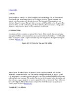
Two styles of stimulus application are possible. In the first style, the stimulus block
instantiates the design block and directly drives the signals in the design block. In Figure
2-6, the stimulus block becomes the top-level block. It manipulates signals clk and reset,
and it checks and displays output signal q.
Figure 2-6. Stimulus Block Instantiates Design Block
The second style of applying stimulus is to instantiate both the stimulus and design
blocks in a top-level dummy module. The stimulus block interacts with the design block
only through the interface. This style of applying stimulus is shown in Figure 2-7
. The
stimulus module drives the signals d_clk and d_reset, which are connected to the signals
clk and reset in the design block. It also checks and displays signal c_q, which is
connected to the signal q in the design block. The function of top-level block is simply to
instantiate the design and stimulus blocks.
Figure 2-7. Stimulus and Design Blocks Instantiated in a Dummy Top-Level Module
Either stimulus style can be used effectively.
[ Team LiB ]
[ Team LiB ]
2.6 Example
To illustrate the concepts discussed in the previous sections, let us build the complete
simulation of a ripple carry counter. We will define the design block and the stimulus
block. We will apply stimulus to the design block and monitor the outputs. As we
develop the Verilog models, you do not need to understand the exact syntax of each
construct at this stage. At this point, you should simply try to understand the design
process. We discuss the syntax in much greater detail in the later chapters.
2.6.1 Design Block
We use a top-down design methodology. First, we write the Verilog description of the
top-level design block (Example 2-3
), which is the ripple carry counter (see Section 2.2,
4-bit Ripple Carry Counter).
Example 2-3 Ripple Carry Counter Top Block
module ripple_carry_counter(q, clk, reset);
output [3:0] q;
input clk, reset;
//4 instances of the module T_FF are created.
T_FF tff0(q[0],clk, reset);
T_FF tff1(q[1],q[0], reset);
T_FF tff2(q[2],q[1], reset);
T_FF tff3(q[3],q[2], reset);
endmodule
In the above module, four instances of the module T_FF (T-flipflop) are used. Therefore,
we must now define (Example 2-4
) the internals of the module T_FF, which was shown
in Figure 2-4
.
Example 2-4 Flipflop T_FF
module T_FF(q, clk, reset);
output q;
input clk, reset;
wire d;
D_FF dff0(q, d, clk, reset);
not n1(d, q); // not is a Verilog-provided primitive. case sensitive
endmodule
Since T_FF instantiates D_FF, we must now define (Example 2-5
) the internals of
module D_FF. We assume asynchronous reset for the D_FFF.
Example 2-5 Flipflop D_F
// module D_FF with synchronous reset
module D_FF(q, d, clk, reset);
output q;
input d, clk, reset;
reg q;
// Lots of new constructs. Ignore the functionality of the
// constructs.
// Concentrate on how the design block is built in a top-down fashion.
always @(posedge reset or negedge clk)
if (reset)
q <= 1'b0;