Microstrip bộ lọc cho các ứng dụng lò vi sóng RF (P1)
Bạn đang xem bản rút gọn của tài liệu. Xem và tải ngay bản đầy đủ của tài liệu tại đây (79.54 KB, 5 trang )
CHAPTER 1
Introduction
The term microwaves may be used to describe electromagnetic (EM) waves with
frequencies ranging from 300 MHz to 300 GHz, which correspond to wavelengths
(in free space) from 1 m to 1 mm. The EM waves with frequencies above 30 GHz
and up to 300 GHz are also called millimeter waves because their wavelengths are
in the millimeter range (1–10 mm). Above the millimeter wave spectrum is the in-
frared, which comprises electromagnetic waves with wavelengths between 1 m
(10
–6
m) and 1 mm. Beyond the infrared spectrum is the visible optical spectrum,
the ultraviolet spectrum, and x-rays. Below the microwave frequency spectrum is
the radio frequency (RF) spectrum. The frequency boundary between RF and mi-
crowaves is somewhat arbitrary, depending on the particular technologies developed
for the exploitation of that specific frequency range. Therefore, by extension, the
RF/microwave applications can be referred to as communications, radar, navigation,
radio astronomy, sensing, medical instrumentation, and others that explore the us-
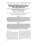
age of frequency spectrums in the range of, say, 300 kHz up to 300 GHz (Figure
1.1). For convenience, some of these frequency spectrums are further divided into
many frequency bands as indicated in Figure 1.1.
Filters play important roles in many RF/microwave applications. They are used to
separate or combine different frequencies. The electromagnetic spectrum is limited
and has to be shared; filters are used to select or confine the RF/microwave signals
within assigned spectral limits. Emerging applications such as wireless communica-
tions continue to challenge RF/microwave filters with ever more stringent require-
ments—higher performance, smaller size, lighter weight, and lower cost. Depending
on the requirements and specifications, RF/microwave filters may be designed as
lumped element or distributed element circuits; they may be realized in various trans-
mission line structures, such as waveguide, coaxial line, and microstrip.
The recent advance of novel materials and fabrication technologies, including
monolithic microwave integrated circuit (MMIC), microelectromechanic system
(MEMS), micromachining, high-temperature superconductor (HTS), and low-tem-
perature cofired ceramics (LTCC), has stimulated the rapid development of new mi-
1
Microstrip Filters for RF/Microwave Applications. Jia-Sheng Hong, M. J. Lancaster
Copyright © 2001 John Wiley & Sons, Inc.
ISBNs: 0-471-38877-7 (Hardback); 0-471-22161-9 (Electronic)
crostrip and other filters. In the meantime, advances in computer-aided design
(CAD) tools such as full-wave electromagnetic (EM) simulators have revolution-
ized filter design. Many novel microstrip filters with advanced filtering characteris-
tics have been demonstrated.
It is the main objective of this book to offer a unique and comprehensive treat-
ment of RF/microwave filters based on the microstrip structure, providing a link to
applications of computer-aided design tools, advanced materials, and technologies
(see Figure 1.2). However, it is not the intention of this book to include everything
that has been published on microstrip filters; such a work would be out of scale in
terms of space and knowledge involved. Moreover, design theories and methods de-
scribed in the book are not only for microstrip filters but directly applicable to other
types of filters, such as waveguide filters.
Although the physical realization of filters at RF/microwave frequencies may
vary, the circuit network topology is common to all. Therefore, the technique con-
tent of the book begins with Chapter 2, which describes various network concepts
and equations; theses are useful for the analysis of filter networks. Chapter 3 then
introduces basic concepts and theories for design of general RF/microwave filters
(including microstrip filters). The topics cover filter transfer functions (such as But-
terworth, Chebyshev, elliptic function, all pass, and Gaussian response), lowpass
2
INTRODUCTION
300 GHz
1 mm
30 GHz
10 mm
3 GHz
10 cm
300 MHz
1 m
30 MHz
10 m
3 MHz
100 m
140-220 GHz
110-170 GHz
75-110 GHz
60-90 GHz
50-70 GHz
40-60 GHz
33-50 GHz
26.5-40 GHz
18-26.5 GHz
12.4-18 GHz
8-12.4 GHz
4-8 GHz
2-4 GHz
1-2 GHz
300-3000 MHz
30-300 MHz
Frequency
range
Band
designation
G-band
D-band
W-band
E-band
V-band
U-band
Q-band
Ka-band
K-band
Ku-band
X-band
C-band
S-band
L-band
UHF-band
VHF-band
Radio Frequency, Microwaves
Wavelength
Frequency
300 kHz
1 km
FIGURE 1.1 RF/microwave spectrums.
prototype filters and elements, frequency and element transformations, immittance
(impedance/admittance) inverters, Richards’ transformation, and Kuroda identities
for distributed elements. Effects of dissipation and unloaded quality factors of filter
elements on filter performance are also discussed.
Chapter 4 summarizes basic concepts and design equations for microstrip lines,
coupled microstrip lines, and discontinuities, as well as lumped and distributed
components, which are useful for design of filters. In Chapter 5, conventional mi-
crostrip lowpass and bandpass filters, such as stepped-impedance filters, open-stub
filters, semilumped element filters, end- and parallel-coupled half-wavelength res-
onator filters, hairpin-line filters, interdigital and combline filters, pseudocombline
filters and stub-line filters, are discussed with instructive design examples.
Chapter 6 discusses some typical microstrip highpass and bandstop filters. These
include quasilumped element and optimum distributed highpass filters, narrow-
band and wide-band bandstop filters, as well as filters for RF chokes. Design equa-
tions, tables and examples are presented for easy references.
The remaining chapters of the book deal with more advanced topics, starting
with Chapter 7, which introduces some of advanced materials and technologies for
RF/microwave filter applications. These include high-temperature superconductors
(HTS), ferroelectrics, MEMS or micromachining, hybrid or monolithic microwave
integrated circuits (MMIC), active filters, photonic bandgap (PBG) materials/struc-
tures, and low-temperature cofired ceramics (LTCC).
INTRODUCTION
3
Microstrip Filters
Computer-aided
design
High-temperature
superconductor
MEMS
Micromachining
Hybrid/monolithic
integrated circuits
Photonic bandgap
materials/structures
Low-temperature
cofired ceramics
RF/Microwave
education
Ferrite and
ferroelectrics
FIGURE 1.2 Microstrip filter linkage.
Chapter 8 presents a comprehensive treatment of subjects regarding coupled res-
onator circuits. These are of importance for design of RF/microwave filters, in par-
ticular the narrow-band bandpass filters, which play a significant role in many ap-
plications. There is a general technique for designing coupled resonator filters,
which can be applied to any type of resonator despite its physical structure. For ex-
ample, it can be applied to the design of waveguide filters, dielectric resonator fil-
ters, ceramic combline filters, microstrip filters, superconducting filters, and micro-
machined filters. This design method is based on coupling coefficients of
intercoupled resonators and the external quality factors of the input and output res-
onators. Since this design technique is so useful and flexible, it would be desirable
to have a deep understanding not only of its approach, but also its theory. For this
purpose, the subjects cover the formulation of the general coupling matrix, which is
of importance for representing a wide range of coupled-resonator filter topologies,
the general theory of couplings for establishing the relationship between the cou-
pling coefficient and the physical structure of coupled resonators. This leads to a
very useful formulation for extracting coupling coefficients from EM simulations
or measurements. Formulations for extracting the external quality factors from fre-
quency responses of the externally loaded input/output resonators are derived next.
Numerical examples are followed to demonstrate how to use these formulations to
extract coupling coefficients and external quality factors of microwave coupling
structures for filter designs.
Chapter 9 is concerned with computer-aided design (CAD). Generally speaking,
any design that involves using computers may be called CAD. There have been ex-
traordinary recent advances in CAD of RF/microwave circuits, particularly in full-
wave electromagnetic (EM) simulations. They have been implemented both in com-
mercial and specific in-house software and are being applied to microwave filter
simulation, modeling, design, and validation. The developments in this area are cer-
tainly being stimulated by increasing computer power. Another driving force for the
developments is the requirement of CAD for low-cost and high-volume production.
In general, besides the investment for tooling, materials and labor mainly affect the
cost of filter production. Labor costs include those for design, fabrication, testing,
and tuning. Here the costs for the design and tuning can be reduced greatly by using
CAD, which can provide more accurate design with less design iterations, leading to
first-pass or tuneless filters. This chapter discusses computer simulation and/or
computer optimization. It summarizes some basic concepts and methods regarding
filter design by CAD. Typical examples of the applications, including filter synthe-
sis by optimization, are described. Many more CAD examples, particularly those
based on full-wave EM simulation, can be found through this book.
In Chapter 10, we discuss the designs of some advanced filters, including selec-
tive filters with a single pair of transmission zeros, cascaded quadruplet (CQ) fil-
ters, trisection and cascaded trisection (CT) filters, cross-coupled filters using
transmission line inserted inverters, linear phase filters for group delay equaliza-
tion, and extracted-pole filters. These types of filters, which are different from con-
ventional Chebyshev filters, must meet the stringent requirements of RF/microwave
systems, particularly wireless communications systems.
4
INTRODUCTION
Chapter 11 is intended to describe novel concepts, methodologies, and designs
for compact filters and filter miniaturization. The new types of filters discussed in-
clude ladder line filters, pseudointerdigital line filters, compact open-loop and hair-
pin resonator filters, slow-wave resonator filters, miniaturized dual-mode filters,
multilayer filters, lumped-element filters, and filters using high-dielectric constant
substrates.
The final chapter of the book (Chapter 12) presents a case study of high-temper-
ature superconducting (HTS) microstrip filters for cellular base station applications.
The study starts with a brief discussion of typical HTS subsystems and RF modules
that include HTS microstrip filters for cellular base stations. This is followed by
more detailed descriptions of the developments of duplexers and preselect bandpass
filters, including design, fabrications, and measurement. The work presented in this
chapter has been carried out mainly for a European research project called Super-
conducting Systems for Communications (SUCOMS), in which the authors have
been involved. The objective of the project is to construct an HTS-based transceiver
for mast-mounted DCS1800 base stations, but it can be interfaced with the Global
System for Mobile Communication or GSM-1800 base station. It can also be modi-
fied for other mobile communication systems such as the Personal Communication
System (PCS) and the future Universal Mobile Telecommunication System
(UMTS).
INTRODUCTION
5