FLUKE - RJ45 Plug, The weakest link in High performance Cabling system
Bạn đang xem bản rút gọn của tài liệu. Xem và tải ngay bản đầy đủ của tài liệu tại đây (68.05 KB, 3 trang )
Application Note
The Weakest Link in High-Performance
Cabling Systems
A new-found respect
Cabling is normally installed long before
furniture or active equipment, and more
than 95% of all new installations are tested
to the Permanent Link model, which
excludes the patch cords at both ends. The
idea is that the link is tested and certified
for the promised level of performance (nor-
mally Category 5e or 6), and then patch
cords are added later when the network is
installed. This model works well if the per-
formance of the patch cords meets the per-
formance of the installed link – which often
is not the case.
Most cabling professionals know that the
TIA published TIA 568B in April of 2001,
and that this standard includes performance
requirements for Category 5e cabling. What
many don’t know is why the standard took
so long to be finished. One reason was the
discovery that patch cord performance could
vary in unpredictable ways.
Imagine putting shopping cart
wheels on a high-performance
car? Or how about putting only
16 MB of RAM in that new 1.2
GHz Pentium 4 laptop system?
Think of the money you’d save!
Intuitively, you know that this
is a false economy, and that
the tires you buy should match
the performance of the vehicle
for which they’re intended.
Similarly, the memory in your
laptop should be appropriate
for the processor, speed, and
hard disk of the system. Yet,
many network installers and
owners will carefully review
structured cabling systems, go
through lengthy evaluations,
do a performance “bake off”
with sample links, and then
after the best system is
selected and installed, use
any old patch cord. While
patch cords have often been
considered non-differentiated
commodities, it’s time they
get the respect they deserve.
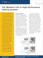
Tests of Return Loss were made on
Category 5 patch cords. Fluke Networks, a
manufacturer of cable test equipment in
Everett, Wash., measured the same patch
cord in two different positions as shown
below. There was no kinking, sharp bends, or
cable abuse - just a simple re-positioning of
the patch cord. This is just the sort of repo-
sitioning that end users would commonly do
as they move a cord between their PC and
the wall outlet. The results were surprising.
Return Loss of position A was more than
4 dB better than in position B! This was
enough to mean one link passed and the
other failed. This is a common error because
in the TSB-67 days, installers weren’t
required to measure Return Loss. This was a
“new” measurement, so its effects were not
considered when patch cords were designed
and manufactured.
Get a unique view into patch cord performance with Fluke Networks’
DSP Patch Cord Test Solution
Test Position A
Test Position B
The weakest link
If you consider the entire structured cabling
Channel, from the PC to the switch, the
weakest link is the modular plug. This is the
point that has the potential for the lowest
performance. Why? Pairs get untwisted and
jammed into a small space, they are crossed
over each other and split, and then they are
put in parallel with flat plates. Often,
mechanical crimps are used to hold the
cable in the plug. These crimps can crush
and deform the conductors, creating imped-
ance changes that contribute to Return
Loss. Cords take a lot of abuse; they are
pulled around desks and run over by chair
wheels, stretched tight around fixtures and
flattened by heavy furniture.
When you consider that the goal is to
try to continue the same matched electrical
performance of the horizontal cable, it’s a
marvel that manufacturers of patch cords
can mimic the transmission of the cable so
well through two modular plugs and a
length of stranded cable.
And just where are these patch cords
located? They are the closest parts of the
structured cabling system to the active
components. They are placed where the
outbound signals strengths are highest, and
inbound signals are weakest. A small
impedance anomaly that causes a 3 or 4%
reflection does a lot more damage to the
integrity of the signal transmission when it
is located at a few feet from the end (in
patch cords) versus somewhere in the
middle of a link. This is also true for
NEXT anomalies.
End users need to consider Channel
performance, not Permanent Link perform-
ance, when they are specifying structured
cabling requirements. The cable plant is
likely to have a much longer life cycle than
the active equipment, so planning should
anticipate all future needs for bandwidth
and capacity. Marginal cords might be okay
today for 10/100BASE-T Ethernet, but not
for Gigabit Ethernet or future applications.
Advanced applications tend to use multiple
pair transmission schemes and bidirectional
communication on the same pair(s), which
makes the performance of the patch cord
vital to the quality or error rate of the
application.
The need for speed
Category 6 installations have some special
requirements. The performance of Category 6
is much higher than Category 5 or 5e, espe-
cially for NEXT and Return Loss. For opti-
mum performance plugs and jacks must be
“centered” and well matched. As a result of
the many studies to define component spec-
ifications, the variability between plug and
jack is now much better understood, and
incompatibility issues are diminishing.
However, it is still vital that for Category 6
systems you follow the recommendation of
the supplier and use only approved patch
cords. Otherwise there is a real risk you will
have a “good cord” that is not well matched
to your system and suffer degraded Channel
performance.
What can end users do? How can you
tell if you have a good cord? They all appear
similar, and all have official-looking certifi-
cation stamps along the sides. Clearly, a
wiremap test is not enough. Testing in the
Channel is much better, but not sufficient
either. Why? Permanent Links with sufficient
headroom can use marginal patch cords and
still pass Channel requirements, but if the
same patch cord is added to a marginal
Permanent Link, the Channel would fail.
Aside from continuity testing, patch
cords should be tested on every pair combi-
nation for both NEXT and Return Loss. They
should be tested according to TIA guidelines
for patch cord tests (special fixtures and
limits, NOT a Channel test!). This means
they must be tested on a standards-compli-
ant fixture. Otherwise, you could “pass,” but
if the jack in the fixture wasn’t properly
centered, your pass means nothing.
Fluke Networks DSP-4300 with DSP Patch Cord Test Adapters
Then there is the issue of repeatability,
and how well the cords stand up to being
flexed or coiled or run over by chair wheels.
For years, Fluke Networks made field tester
cords from patch cords sent by different
suppliers. The company found performance
varied widely, and began to perform 100%
incoming inspection to ensure the perform-
ance matched its high internal standards
(which were admittedly tougher than neces-
sary for normal office use). Did these cords
all pass wiremap? Sure. Did they work fine
for a 10/100 application? Yes. What about
their performance after a great deal of flex-
ing, coiling, and uncoiling on Gigabit
Ethernet? Many didn’t make the grade.
Tests for success
End users really only have a couple of
options. First you can follow the recommen-
dations of your supplier, and only choose to
buy approved cords that are designed to go
with the installation specified. In most
cases this is the simplest way to avoid
potential performance degradation, espe-
cially on Category 6 installations.
Another alternative is to test the cords
yourself. Field testers are now available,
such as the Fluke Networks DSP-4000 Series,
that have optional patch cord adapter
fixtures designed with special hardware and
software to exactly meet TIA patch cord test
requirements. In fact, these products are
already in use at many patch cord manufac-
turing facilities worldwide. This provides a
means to check legacy cords, as well as
verify incoming product to meet require-
ments consistency from cord to cord.
Don’t treat your patch cords with
indifference. They are a vital part of your
network. If you take the time and spent a
little more to ensure you have a good
quality cord, you will enjoy fewer bit errors,
greater channel throughput, more system
margin and less network downtime.
Fluke Networks, Inc.
P.O. Box 777, Everett, WA USA 98206-0777
(800) 283-5853 Fax (425) 446-5043
Western Europe
00800 632 632 00, +44 (0)1923 281 300
Fax 00800 225 536 38, +44 (0)1923 281 301
Email:
Canada (800) 363-5853 Fax (905) 890-6866
EEMEA +31 (0)40 267 5119
Fax +31 (0)40 267 5180
Other countries call (425) 446-4519
Fax (425) 446-5043
E-mail:
Web access:
©
2002 Fluke Networks, Inc. All rights reserved.
Printed in U.S.A. 11/2002 2062074 A-ENG-N Rev A
NETWORKSUPERVISION