GSM switching services and protocols P12
Bạn đang xem bản rút gọn của tài liệu. Xem và tải ngay bản đầy đủ của tài liệu tại đây (565.75 KB, 26 trang )
GSM ± The Story Goes On
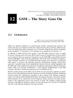
12.1 Globalisation
GSM is now in more countries than McDonalds.
Mike Short, Chairman MoU Association 1995±1996
GSM was initially designed as a pan-European mobile communication network, but
shortly after the successful start of the ®rst commercial networks in Europe, GSM systems
were also deployed on other continents (e.g. in Australia, Hong Kong, and New Zealand).
In the meantime, 373 networks in 142 countries are in operation (see Section 1.3).
In addition to GSM networks that operate in the 900 MHz frequency band, so-called
Personal Communication Networks (PCN) and Personal Communication Systems (PCS)
are in operation. They are using new frequencies around 1800 MHz, and in North America
around 1900 MHz. Apart from the peculiarities that result from the different frequency
range, PCN/PCS networks are full GSM networks without any restrictions, in particular
with respect to services and signaling protocols. International roaming among these
networks is possible based on the standardized interface between mobile equipment and
the SIM card, which enables personalization of equipment operating in different frequency
ranges (SIM card roaming). Furthermore, a more general standardization of the SIM
concept could allow worldwide roaming across non-GSM networks.
Besides roaming based on the SIM card, the MoU has put increasing emphasis on multi-
band systems and multiband terminals during the last years (dualband, triband). Multiband
systems permit the simultaneous operation of base stations with different frequency
ranges. In connection with multiband terminals, this approach leads to a powerful concept.
Such terminals can be operated in several frequency bands, and they can adapt automa-
tically to the frequencies used in the network at hand. This enables roaming among
networks with different frequency ranges, but also automatic cell selection in multiband
networks with different frequencies becomes possible.
12
GSM Switching, Services and Protocols: Second Edition. Jo
È
rg Eberspa
È
cher,
Hans-Jo
È
rg Vo
È
gel and Christian Bettstetter
Copyright q 2001 John Wiley & Sons Ltd
Print ISBN 0-471-49903-X Online ISBN 0-470-84174-5
12.2 Overview of GSM Services in Phase 21
GSM is not a closed system that does not undergo any change. The GSM standards are
being enhanced; and in the current phase of standardization (Phase 21) several individual
topics are being discussed. Phase 1 of the GSM implementation contained basic teleser-
vices ± in the ®rst place voice communication ± and a few supplementary services, which
had to be offered by all network operators in 1991 when GSM was introduced into the
market. The standardization of Phase 2 was completed in 1995 with market introduction
following in 1996. Essentially, ETSI added more of the supplementary services, which had
been planned already when GSM was initially conceived and which were adopted from the
®xed ISDN (see Section 4.3). These new services made it necessary to rework large parts
of the GSM standards. For this reason, networks operating according to the revised stan-
dard are also called GSM Phase 2 [45]. However, all networks and terminals of Phase 2
preserve the compatibility with the old terminals and network equipment of Phase 1, i.e. all
new standard development had to be strictly backward compatible.
The topics of Phase 21 deal with many aspects ranging from radio transmission to
communication and call processing. However, there is no complete revision of the GSM
standard; rather single subject areas are treated as separate standardization units, with the
intent of allowing them to be implemented and introduced independently from each other.
12 GSM ± The Story Goes On
272
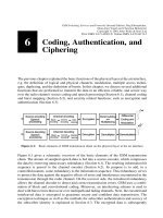
Figure 12.1: Evolution of GSM
Thus GSM systems can evolve gradually, and standardization can meet market needs in a
¯exible way. However, with this approach, a unique identi®cation of a GSM standard
version becomes impossible. The designation GSM Phase 21 is supposed to indicate this
openness [45], suggesting an evolutionary process with no endpoint in time or prescribed
target dates for the introduction of new services. The GSM standards are now published in
so-called releases (e.g. Release 97, 98, 99, and 2000).
A large menu of technical questions is being addressed, only a few of which are presented
as examples in the following. Figure 12.1 illustrates the evolution of GSM, from the initial
digital speech services toward the 3rd generation of mobile communications (UMTS/IMT-
2000). In particular, it shows the services of Phase 21 that are covered in this book. Most
of these services are already offered by GSM network providers today and can be used with
enhanced mobile equipment. Some other services are in the planning stage at the time of
this writing.
12.3 Bearer and Teleservices of GSM Phase 21
Whereas GSM Phase 2 de®ned essentially a set of new supplementary services, Phase 21
is also addressing new bearer and teleservices. In this section we give an overview of these
new speech and data services. They signi®cantly improve the GSM speech quality and
make the utilization of available radio resources much more ef®cient. Furthermore, the new
data services are an important step toward wireless Internet access via cellular networks.
12.3.1 Improved Codecs for Speech Services: Half-Rate Codec, EFR
Codec, and AMR Codec
One of the most important services in GSM is (of course) voice service. Thus it is obvious,
that voice service has to be further improved. In ®rst place is the development of new
speech codecs with two competing objectives:
² better utilization of the frequency bands assigned to GSM and
² improvement of speech quality in the direction of the quality offered by ISDN networks,
which is primarily requested by professional users.
Half-Rate codec ± The reason for improved bandwidth utilization is to increase the
network capacity and the spectral ef®ciency (i.e. traf®c carried per cell area and frequency
band). Early plans were already in place to introduce a half-rate speech codec. Under good
channel conditions, this codec achieves, in spite of the half bit rate, almost the same speech
quality as the full-rate codec used so far. However, quality loss occurs in particular for
mobile-to-mobile communication, since in this case (due to the ISDN architecture) one has
to go twice through the GSM speech coding/decoding process. These multiple, or tandem,
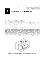
conversions degrade speech quality. The end-to-end transmission of GSM-coded speech is
intended to avoid multiple unnecessary transcoding and the resulting quality loss (Figure
12.2) [45]. This technique has been passed under the name Tandem Free Operation (TFO)
in GSM Release 98.
Enhanced Full-Rate (EFR) codec ± A very important concern is the improvement of
12.3 Bearer and Teleservices of GSM Phase 21
273
speech quality. Speech quality that is close to the one found in ®xed networks is especially
important for business applications and in cases where GSM systems are intended to
replace ®xed networks, e.g. for fast installation of telecommunication networks in areas
with insuf®cient or missing telephone infrastructure.
Work on the Enhanced Full-Rate (EFR) codec was therefore considered of high priority.
This EFR is a full-rate codec (net bit rate 12.2 kbit/s). Nevertheless, it achieves speech
quality clearly superior to the previously used full-rate codec. It has been initially stan-
dardized and used in North American DCS1900 networks [45] and has been implemented
in GSM with very good success. Instead of using the Regular Pulse Excitation±Long Term
Prediction (RPE-LTP) coding scheme (see Section 6.1), a so-called Algebraic Code Exci-
tation±Linear Prediction (ACELP) is employed.
The EFR speech coder delivers data blocks of 244 information bits to the channel encoder
(compare with Table 6.2). In addition to grading the bits into important Class I bits and less
important Class II bits, EFR further divides into Class Ia bits and Class Ib bits. A special
preliminary channel coding is employed for the most signi®cant bits: eight parity bits
(generated by a Cyclic Redundancy Check (CRC) coding) and eight repetition bits are
added to provide additional error-detection. The resulting 260 bits are processed by the
block encoder as described in Section 6.2.1.1. For convolutional coding of Class I bits the
convolutional encoder de®ned by the generator polynomials G0 and G1 is employed.
Adaptive Multi-Rate (AMR) codec ± The speech codecs mentioned before (full-rate,
half-rate, and EFR) all use a ®xed source/information bit rate, which has been optimized
for typical radio channel conditions. The problem with this approach is its in¯exibility:
whenever the channel conditions are much worse than usual, very poor speech quality will
result, since the channel capacity assigned to the mobile station is too small for error free
12 GSM ± The Story Goes On
274
Figure 12.2: Through-transport of GSM-coded speech in Phase 21
for mobile-to-mobile connections (tandem free operation)
transmission. On the other hand, radio resources will be wasted for unneeded error protec-
tion if the radio conditions are better than usual.
To overcome these problems, a much more ¯exible codec has been developed and stan-
dardized: the Adaptive Multi-Rate (AMR) codec. It can improve speech quality by adap-
tively switching between different speech coding schemes (with different levels of error
protection) according to the current channel quality. To be more precise, AMR has two
principles of adaptability [11]: channel mode adaptation and codec mode adaptation.
Channel mode adaptation dynamically selects the type of traf®c channel that a connection
should be assigned to: either a full-rate (TCH/F) or a half-rate traf®c channel (TCH/H).
The basic idea here is to adapt a user's gross bit rate in order to optimize the usage of radio
resources. If the traf®c load in a cell is high, those connections using a TCH/F (gross bit
rate 22.8 kbit/s) and having good channel quality should be switched to a TCH/H (11.4
kbit/s). On the other hand, if the load is low, the speech quality of several TCH/H connec-
tions can be improved by switching them to a TCH/F. The signaling information for this
type of adaptation is done with existing protocols on GSM signaling channels; the switch-
ing between full-rate and half-rate channels is realized by an intracell handover.
The task of codec mode adaptation is to adapt the coding rate (i.e. the trade-off between the
level of error protection versus the source bit rate) according to the current channel
conditions. When the radio channel is bad, the encoder operates at low source bit rates
at its input and uses more bits for forward error protection. When the quality of the channel
is good, less error protection is employed.
The AMR codec consists of eight different modes with source/information bit rates
ranging from 12.2 kbit/s to 4.75 kbit/s (see Table 12.1). All modes are scaled versions
of a common ACELP basis codec.
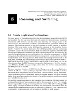
From the results of link quality measures, an adaptation unit selects the most appropriate
codec mode. Figure 12.3 illustrates the AMR encoding principle. Channel coding is
performed using a punctured recursive systematic convolutional code. Since not all bits
of the voice data are equally important for audibility, AMR also employs an Unequal Error
Protection (UEP) structure. The most important bits (Class Ia; e.g. mode bits and LPC
12.3 Bearer and Teleservices of GSM Phase 21
275
Table 12.1: AMR codec modes
Source data rate in kbit/s 12.2 10.2 7.95 7.4 6.7 5.9 5.15 4.75
Information bits per block 244 204 159 148 134 118 103 95
±Class Ia bits
(CRC-protected)
81 65 75 61 55 55 49 39
±Class Ib bits
(not CRC-protected)
163 139 84 87 79 63 54 56
Rate R of convolutional
encoder
1/2 1/3 1/3 1/3 1/4 1/4 1/5 1/5
Output bits from
convolutional encoder
508 642 513 474 576 520 565 535
Punctured bits 60 194 65 26 128 72 117 87
coef®cients) are additionally protected by a Cyclic Redundancy Check (CRC) code with 6
parity bits. On the receiver side, the decoder will discard the entire speech frame if the
parity check fails. Also the degree of puncturing depends on the importance of the bits. At
the end of the encoding process, a block with a ®xed number of gross bits results, which is
subsequently interleaved to reduce the number of burst errors.
Since the channel conditions can change rapidly, codec mode adaptation requires a fast
signaling mechanism. This is achieved by transmitting the information about the used
codec mode, link control, and DTX, etc. together with the speech data in the TCH, i.e. a
special inband signaling is employed.
We give an example: the 12.2 kbit/s codec for a TCH/F operates with 244 source bits
(12.2 kbit/s £ 20 ms), which are ®rst rearranged to subjective importance. By adding six
CRC bits for Class 1a bits, we obtain 250 bits. The subsequent recursive convolutional
encoder, de®ned by the two generators 1 and G
1
=G
0
d
4
1 d
3
1 d 1 1=d
4
1 d
3
1 d,
with rate R < 1/2, maps those bits to 508 bits. Next, 60 bits are punctured, which results in
an output sequence of 448 bits. Together with the encoded inband signaling (8 bits) this
block is interleaved and ®nally mapped to bursts. The resulting gross bit rate is thus
456 bits/20 ms 22.8 kbit/s.
12.3.2 Advanced Speech Call Items (ASCI)
GSM systems of Phase 2 offer inadequate features for group communications. For exam-
ple, group call or ``push-to-talk'' services with fast connection setup as known from private
radio or digital trunked radio systems (e.g. TETRA), are not offered. However, such
services are indispensable for most closed user groups (e.g. police, airport staff, railroad
or taxi companies). In particular railroad operators had a strong request for such features.
In 1992, their international organization, the Union Internationale des Chemins de Fer
(UIC), selected the GSM system as their standard [45]. This GSM-based uniform inter-
national railway communication system should replace a multitude of incompatible radio
systems.
In this section we describe the standardized speech teleservices that offer functionality for
group communication: the Voice Broadcast Service (VBS) and the Voice Group Call
Service (VGCS). In addition, the Enhanced Multi-Level Precedence and Pre-emption
Service (eMLPP) is used to assign and control priorities to users and their calls (e.g. for
emergency calls). All those services together are referred to as Advanced Speech Call
Items (ASCI).
12 GSM ± The Story Goes On
276
Figure 12.3: AMR channel encoding principle (bit numbers for TCH/F)
12.3.2.1 Voice Broadcast Service (VBS)
The Voice Broadcast Service (VBS) allows a user to broadcast a speech message to several
other users within a certain geographical area. The user who initiates the call can only send
(``speaker''), and all others can only listen (``listeners'').
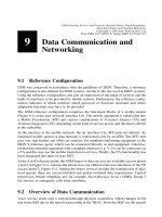
Figure 12.4 gives a schematic illustration of a VBS scenario. Mobile users who are inter-
ested in a certain VBS group subscribe it and will then receive broadcast calls of this
group. A special permission is needed, however, for the right to send broadcast calls, i.e.
for the right to act as a speaker. The subscribed VBS groups are stored on the user's SIM
card, and if a subscriber does not want to receive VBS calls for a certain time, he or she can
deactivate them. Besides mobile GSM users, also a prede®ned group of ®xed telephone
connections can participate in the VBS service (e.g. dispatchers, supervisors, operators, or
recording machines).
12.3 Bearer and Teleservices of GSM Phase 21
277
Figure 12.4: VBS scenario (schematic illustration)
Figure 12.5: Some examples of group call areas
System Concept and Group Call Register ± The area in which a speech broadcast call is
offered is referred to as group call area. As illustrated in Figure 12.5, in general, this area
consists of several cells. A group call area may comprise cells of several MSC areas and
even of several PLMNs. One MSC is responsible for the handling of the VBS. It is called
Anchor MSC. In case a voice broadcast should also be transmitted in cells that are not
within the service area of this MSC (i.e. if the group call area contains also cells belonging
to other MSCs), the MSCs of those cells are also involved. They are then denoted as Relay
MSCs.
The VBS-speci®c data is stored in a Group Call Register (GCR). Figure 12.6 shows the
extended GSM system architecture. The GCR contains the broadcast call attributes for
each VBS group, which are needed for call forwarding and authentication. For example:
² Which cells belong to the group call area?
² Which MSC is the responsible anchor MSC?
² In which cells are group members currently located, i.e. in which cells is a voice
message to be broadcast?
² To which other MSCs is the voice message to be forwarded to reach all group members
who are currently located in the group call area?
² To which external ®xed telephone connections is the broadcast message addressed?
² Which ®xed telephone connections are allowed to act as speakers?
Call Establishment and Logical Channels ± A mobile station that intends to initiate a
voice broadcast call sends a service request to the BSS. The request contains the Group ID
of the VBS group to be called. Thereupon, the responsible MSC queries the user's pro®le
12 GSM ± The Story Goes On
278
Figure 12.6: Extension of the GSM system architecture with the GCR
from the VLR and checks whether the user is allowed to act as speaker for the stated group.
Afterward, some VBS-speci®c attributes are requested from the GCR. If the broadcast call
should also be transmitted in cells that do not belong to the current MSC, an anchor MSC is
determined. The anchor MSC then forwards the VBS attributes to all relay MSCs, which
then request all affected BSCs to allocate a traf®c channel in the respective cells, and to
send out noti®cation messages on the NCH (see Section 5.1). When a mobile station
receives such a message and it is also subscribing to the respective VBS group, it changes
to the given traf®c channel and listens to the voice broadcast in the downlink. The speaker
is then informed about the successful connection setup and can start talking. The noti®ca-
tion message is periodically repeated on the NCH until the speaker terminates the call.
In contrast to the paging procedure in conventional GSM calls, the individual mobile users
and their mobile stations are not explicitly addressed by an IMSI or TMSI but with the
Group ID of the VBS group. Furthermore, the mobile stations do not acknowledge the
reception of VBS calls to the network. To realize the service, traf®c channels are not
allocated to individual subscribers, but the voice signal of the speaker is broadcast to all
listening participants in a cell on one group channel. Thus, in each participating cell, only
one full-rate channel is occupied (as in regular voice calls).
12.3.2.2 Voice Group Call Service (VGCS)
Another group communication service is the Voice Group Call Service (VGCS). The
VGCS de®nes a closed user group communication service, where the right to talk can
now be passed along within the group during a call by using a push-to-talk mechanism as
in mobile radio. This principle is illustrated in Figure 12.7: User 1 initializes a group call
and speaks, while the other users listen. Afterward, User 1 releases the channel and
changes into listener mode. Now, each of the subscribers may apply for the right to become
speaker. For example, User 4 requests the channel, and the network assigns it to him/her.
He or she talks, releases the channel, and changes back to listener mode. Finally, the group
call is terminated by the initiator (in general). Whereas the information ¯ow in the VBS is
simplex, the VGCS can be regarded as a half-duplex system (compare Figures 12.4 and
12.7).
The fundamental concepts and entities of the VBS, e.g. the de®nition of group call areas,
group IDs, the GCR, and anchor and relay MSCs are also used in the VGCS.
12.3 Bearer and Teleservices of GSM Phase 21
279
Figure 12.7: Group call scenario (schematic illustration)
Logical Channels ± A traf®c channel is allocated in each cell of the group call area that is
involved in the VGCS. All group members listen to this channel in the downlink, and only
the speaker uses it in the uplink. Therefore, in addition to the tasks for VBS calls, the
network must also control uplink radio resources. The network indicates in the downlink to
all mobile stations whether the uplink channel is in use or not. If the channel is free, the
group members may send access bursts. Collisions that occur with simultaneous requests
are resolved, and the network chooses one user who obtains the channel and thus has the
right to talk.
12.3.2.3 Enhanced Multi-Level Precedence and Pre-emption (eMLPP)
Priority services enable a network to process calls with a priority class (precedence level).
If the network load is high, calls with high priority can then be treated in a preferred
manner, and resources for low priority calls can be deallocated. In the extreme case, a call
with low priority can be dropped because a call with high priority arrives (pre-emption).
The control of priorities in GSM is called Enhanced Multi-Level Precedence and Pre-
emption (eMLPP). It is a supplementary service for point-to-point speech services as well
as for VBS and VGCS. The principle of eMLPP is based on the Multi-Level Precedence
and Pre-emption (MLPP) [33] method used in SS#7. In doing so, MLPP has been
enhanced with functions for priority control at the air interface. Table 12.2 lists all priority
classes of eMLPP. Besides the ®ve precedence levels that are used in MLPP (Classes 0±4),
two additional levels with higher priority are de®ned (Classes A and B). The table also
shows whether a call with higher priority may terminate a call with lower priority. It is
important to note that only the operator may use calls of Class A and B, such that for
example an emergency call over VBS or VGCS can be initiated in disaster situations. Calls
of this class can only be employed within the service area of one MSC. The other ®ve
classes can be utilized within the entire PLMN and also in combination with the MLPP of
ISDN. The highest priority call that a subscriber is allowed to use is stored on his or her
SIM card and in the HLR.
12 GSM ± The Story Goes On
280
Table 12.2: Priority classes in eMLPP
Class Used by Connection
setup
Call interruption
(pre-emption)
Example
A Operator Fast (1±2 s) Yes Highest priority; VBS/
VGCS emergency calls
B Operator Normal (,5 s) Yes Calls of operator
0 Subscriber Normal (,5 s) Yes Emergency calls of users
1 Subscriber Slow (,10 s) Yes
2 Subscriber Slow (,10 s) No
3 Subscriber Slow (,10 s) No Standard priority
4 Subscriber Slow (,10 s) No Lowest priority