XÂY DỰNG PHẦN CỨNG ĐẾM SỐ CÂY THÉP TRONG BÓ THÉP BẰNG XỬ LÝ ẢNH
Bạn đang xem bản rút gọn của tài liệu. Xem và tải ngay bản đầy đủ của tài liệu tại đây (688.18 KB, 6 trang )
<span class='text_page_counter'>(1)</span><div class='page_container' data-page=1>
<b>CONSTRUCTING HARDWAVE TO COUNT NUMBER OF STEEL BAR </b>
<i><b>IN THE STEEL BUNCHES BY IMAGE PROCESSING </b></i>
<b>Pham Duc Long* </b>
<i>University of Information and Communication Technology - TNU </i>
ABSTRACT
In this paper, we propose a new algorithm that is used to exactly count number of steel bars in the
bundles via their image of each bunch. We also bring out an initial experiment perform on
hardware to realized this algorithm for speed up processing. On that way the device can
stand-alone without PC. Experiments are implemented on the kit Altera DE2. The results proved the
correctness of algorithm and solution.
<i><b>Keywords: count by image processing, count bar steel, image processing on the hardware</b></i>
THEREQUIRESFROMPRACTICE*
<b>Counting the number of steel bar in a steel bundle </b>
Currently, in Vietnam in the rough rolling
mill for using in the construction haves
usually two common products are rolled steel
and steel bar. Steel bars from the factory are
sold to major agents in units of weight (tons
of cargo). But the small agents usually are
selling with number of steel bar. In order to
avoid being stolen during transportation and
to close strengthen warehouse management, it
is important to exactly count the number of
steel bar per bunch corresponding to the
weight of each bundle. Because the weight of
each steel bar has toleran, therefore, it is
impossible division the weight of the steel
bundle by the weight of each steel bar to get
the number of steel bar in the bundle.
<b>Counting by image processing program on </b>
<b>the computer </b>
Counting in the production process: It is
counting each steel bar in the last stage of
process (called the product recall stage).
When number of steel bar is enough then line
is stopped to packing the steel bundle.
Counting by infrared sensors is inaccurate,
because affect of noise in the factory is very
large (the amplitude of the noise can reach
more than 100V). Some factories in Vietnam
often use mechanical counting systems. Due
to reliability of the counter is not high, after a
period of work system is not work anymore.
Currently popular counting at the steel mill in
the country is operated in hand - eye.
*
<i>Email: </i>
Counting in hand-eye are also used after steel
bundling: the worker counters each steel bar
and then paint to this bar to marking it is
counted. The process is performed
continuously until the last bar in the steel
bundle. There was a proposal to count steel
bar by image processing in the production
process. This method performs counting the
steel bars by image processing while they are
moving on the chain conveyor as in [1].
Counting affter steel bars are bouldled: The
method counting the number of steel bars via
image of head side of steel bundls has been
studied by many many researchers around the
world with many techniques such as
Euclidean distance calculation, Hough
transform, neural network, ...in [2], [3], [4],
[5], [6], [7], [8], [9], [10], [11], [12]. However
according to the results announced, there is
not any solution confirms the results
counting 100% accurate.
<i><b>Figure 1. The head side of steel bundle and their image </b></i>
</div>
<span class='text_page_counter'>(2)</span><div class='page_container' data-page=2>
reseach problem and overall results are
received. In the second part of this paper the
algorithm to counting objects perform by
image processing on PC computer and results
is described. In part 3, the experimental
implementation of the algorithm on the kit
FPGA was presented step-by-step, results of
experiments and discussion. And in the
finally is the conclusion of the paper.
ALGORITHM TO COUNT OBJECTS
WHEN THEIR IMAGE ARE TOUCHING
EACH OTHER
<b>Classic counting algorithm by image processing </b>
To count number of objects in an image one
usually uses classical algorithm as: Start from
any pixel in image and check the neighboring
pixels of this pixel. If there are any pixels
associated with it then performing addition
that pixel to the group. Do continuous with
other pixels that are not checked. The number
of pixel groups is the number of objects in the
image. In Figure 2b, the groups are labeled
from 2 to n so that they are not confused with
the black point value of 1. The number of
groups in Figure 2b is n-1 = 7-1 = 6 means
that there are 6 objects in this image.
<i><b>Figure 2. Classic counting method a) Black pixels with </b></i>
<i>a value of 1 b) Labeling the associated pixel groups </i>
In practice because head side of steel bars
often are not flat or due to the different loose
or tight bundles, then their image may be
touching one another like in Figure 1.a, b, c.
With the objects whose images are separated
from each another, the counting them are
simple but when images of objects are
overlapping or touching one another, one will
need more processing and will not achieve
100% accuracy.
<b>Algorithm counts objects with their images </b>
<b>touching together (ACOTT) </b>
In image processing, morphologies are widely
used in both binary and grayscale images. The
two basic operators of morphology are
dilation and erosion. From two these
operators one can build opening and closing
operator (not mentioned here).
The dilation of D (P, M) with the image P and
mask M is shown in Figure 5a: the mask M is
moved over the image P and at each test point
if this bit is 1 then performing disjunction of
bits of the mask with the bits of the image
around the test pixel. The result is D (P, M).
The erosion of E (P, M) with the image P and
mask M is shown in Figure 5b: the mask M is
moved over the image P and at each test point
if this bit is 1 then performing conjunction of
bits of the mask with the bits of the image
around the test pixel. The result is E (P, M).
<i><b>Figure 3. Operator dilation and operator erosion </b></i>
</div>
<span class='text_page_counter'>(3)</span><div class='page_container' data-page=3>
note that because the steel bars in the bundle
can not integrate together, their images can
touching together but can not come too (for
example, can not have image of two steel bar
overlap together in image to their area
become equal 1 or 1.5 times area of the alone
steel bars). This is achieved when the light
conditions are good and the optical axis of the
camera lens coincides with the center axis of
the steel bundle (this is a reasonable
assumption because when capture image the
camera is moved to the head side of the steel
bundle and the lens is parallel to the axis of
the steel bundle). Therefore, when
photographing the head side of steel bundle,
the image of the touching together steel bars
also only as in figure 1.c. This is an important
analysis that leads to the following algorithm:
<i><b>Algorithm to count the objects with their </b></i>
<i><b>image is touching together: </b></i>
- Load a binary image of a single steel bar I1;
- Perform erosion image I1;
- Calculate the area of single steel bar I1 = s0;
- Load image head side of steel bar I2;
- Transform image I2 to binary;
- Remove small objects in the I2 if their area s
are smaller 0.8s0;
- Erosion I2. After this step some touching
together object are separated, but some of
them are still touching, so the area of these
objects is larger than the area of a single
object s0;
- Calculate the area of the objects in image I2;
Number1=0;
Repeat 1: With the objects in image I2
- If (the area of si is approximately s0 (with
the times of erosion on I1 and the times of
erosion on I2 is the same = , the image of a
single steel bar is approximately s0))
Then Number1 = Number1 + 1;
Delete the object si that is counted
{After this step, in the I2 there are only the
touching together objects}.
Repeat 2: With each of the touching together
objects si that remain in the image I2
- Number2 = round(si/s0)
Number = Number1+Number2;
The value of were found experimentally and
depending on the type of steel to be counted,
how many (10, 12, ...) for normal steel
bars or D how much (D10, D12, ...) with
ribbed steel bar. In order to have a fully
automated algorithm with different objects in
future development stages, it is possible to
construct an algorithm that automatically
determines these thresholds of based on the
actual characteristics about diameter of each
type of steel bar in the image.
Illustrated by photos: In Figure 5b, there are
nine objects in which three are separated
objects and one group with two objects and
another group with four objects touching
together. If we use the classic counting
algorithm we will only count 5 objects, and
that is the wrong result. In Figure 5c, we see
that after some times of erosion
morphologies, the groups of objects at 5a
have been separated. However, the results are
not always good, as shown in Fig. 5c, so the
implementation Algorithm counts objects
with their images touching together
(ACOTT) is necessary.
We will implement ACOTT to count the
number of objects in Figure 4d: First count
objects that has area approximately the area
of a single steel bar s0, and then delete these
objects (in this count image Number1 = 98).
After deleting these objects the remaining
groups as shown in Figure 4f. Number2 = 22
and the number of steel bars is Number = 98
+ 22 = 120. The results of performing
algorithm in Matlab is show on Figure 4.
<b>EXPERIMENTS </b>
<b>Experiments on PC </b>
</div>
<span class='text_page_counter'>(4)</span><div class='page_container' data-page=4>
<i><b>Figure 4. Image of head side steel boundle a) </b></i>
<i>color image b) gray image c) binary image d) </i>
<i>binary image affter erosion e) zoom in to image 4d </i>
<i>shown found 2 groups 1 and 2 in that still there </i>
<i>are touching together objects f, g) some group </i>
<i>with touching together objects remain affter delete </i>
<i>single objects </i>
<i><b>Figure 5. Separate objects in image by erosion </b></i>
<i><b>Figure 6. Some photos are used in the experiments </b></i>
The results show that with the steel bar
diameter D10 the results count have not
reached the absolute accuracy. With the
bundles of steel bars from D12 and bigger the
results reach absolute accuracy. This result
lead to implementation ACOTT on the
electronical circuit to create a handle device
independence with PC for count number of
steel bar.
<i><b>Table 1. Result of experiments on PC </b></i>
Diameter of steel bars D10 D12 D14
Accuracy of
counting results
97.2 % 100% 100%
<b>Performance on kit FPGA </b>
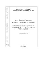
<i>Kit Altera DE2 </i>
<i><b>Figure 7. Kit DE2 of Altera </b></i>
<i>Architecture of computational block: We </i>
experimented put ACOTT into circuits for
realization on kit FPGA DE2 with
computational blocks in Figure 8.
<i><b>Figure 8. Architecture of computating and </b></i>
<i>processing block on kit FPGA DE2 of Altera </i>
The color or gray images obtained from the
camera (or image file) are converted into
binary images and are loaded into RAM1
memory area of the kit DE2. On the RAM2
area performs erosion, counting, deleting,
counting, and summing the final result.
Results are shown on the 7-segment LED
HEX0 of the kit.
<i>Create a data format: </i>
</div>
<span class='text_page_counter'>(5)</span><div class='page_container' data-page=5>
image data format used in the RAM1 of the
FPGA kit is shown in Figure 9.
<i><b>Figure 9. The data structure in the RAM1 of the </b></i>
<i>FPGA </i>
In it - the first line example: ':' is required; the
next two characters '04' index byte value data;
the next four digits '0000' address the input
data; The next two characters '00' are not
used; '41100000' data; 'ab' test code.
<i>Performing of experiment: </i>
In the counting test on the hardware that is
generated from the FPGA technology we
have done on a simple binary image in Figure
5. This image is loaded from a file .BMP with
size of 144x176. After arranging the image
data in the format (Section 3.2.3) the image is
put into RAM1. The morphology used in the
experiment is erosion. This increases the
number of black points in the image. The
effect of erosion is to separate the white
objects that are touching to each other, as
shown in Figure 5c. The mask M is used as
shown in Figure 3. The morphological and the
mediate calculations of the object-counting
algorithm and final result in processing are
storaged in RAM2.
<i>Result </i>
Before load the VHDL code implementation
to the kit, simulation and results of steps of
the algorithm are given on the Figure 10 and
Figure 11.
<i><b>Figure 10. Simulation erosion befor load to kit </b></i>
<i><b>Figure 11. Calculate area of objects in the RAM 2 </b></i>
In the ACOTT algorithm for counting objects
that are touching together, counting the area
of objects is an important task. The area of an
object is equal to the total number of pixels of
that object. Figure 12 shows the results of
calculating the area of an object in the RAM
2. Other steps of the algorithm are also
performed on the same hardware. With the
objects in Figure 5 the result count is as
follows:
<i><b>Figure 12. On the LED HEX0 of the kit DE2 </b></i>
<i>shown number of objects in Figure 5 equal 9 </i>
<i>Discuss </i>
</div>
<span class='text_page_counter'>(6)</span><div class='page_container' data-page=6>
used for the program when processing
sequential type is usually not accounted for
much; This is also an advantage for building
the system.
CONCLUSION
Counting objects by image processing can
receive highly accurate when using the
ACOTT algorithm. With reasonable FPGA
structures, we can harden any algorithm that
has been implemented on a PC in general as
well as with the proposed algorithm. This
allows to creating the block devices that can
operate independently of the computer and
offer faster speeds and greater stability.
Nowadays, it is a research trend very
interested because that promises to give out
many products with high practicality.
REFERENCES
1. Pham Duc Long, Automatical Count steel bars
<i>by image processing, Thai Nguyen University </i>
<i>Jurnal of Science and Technology, Volume 118, </i>
<i>No 04, pg. 119-124, 2014. </i>
2. LUO Shan, HUANG Huan, LIU Jihong, A
Counting Method of Steel Bars Bundle Based on
Image Processing, Micro Computer
Applications,Vol 129 No16, Jun1 2008, pg. 94-97.
3. LUO San-ding, HUANG Jiang-feng, LI Yong,
<i>Method for Steel Bars Recognizing and Counting </i>
<i>Based on Multi-camera Vision Fusion, Computer </i>
Engineering, 2008, Vol.34 No.3, pg. 231-233.
<i>4. KE Long-zhang,YANG Yu-qing, A Real-time </i>
<i>system designing for automatic steel counting </i>
<i>based on DSP and its realization, Hun an Ag ricult </i>
ural Machinery, 2009, Vol 36. No 1, pg. 40-43.
SONG Qiang, XU Ke, XU Jinwu, SUN Hao,
<i>WANG Jinhua, WANG Chunmei, Automatic </i>
<i>Counting Technique for Steel Bars based on </i>
<i>Image Proceessing, Iron and Steel, Vol 39, No 5, </i>
2004, pg. 34-38.
5. Xue Wei, Yuan Pei-xin, Han Qing-da, Chen
<i>Chang-hai, Research on an Automatic Counting </i>
<i>Method for Steel Bars Image, Electrical and </i>
Control Engineering (ICECE), 2010 International
Conference on, 2012, pg. 1644 - 1647.
<i>6. Weiyan Hou, Zhengwei Duan, Xiaodan Liu, A </i>
<i>Template-Covering Based Algorithm to Count the </i>
<i>Bundled Steel Bars, 2011 4th International </i>
Congress on Image and Signal Processing. pg.
1813-1816, 2011.
7. Avadhoot R. Telepatil, Shrinivas A.Patil,
<i>Parameter Estimation of metal blooms using </i>
<i>image processing techniques, International Journal </i>
of Innovative Research in Science, Engineering
and Technology (ISO 3297: 2007 Certified
Organization) Vol. 2, Issue 8, August 2013.
<i>8. Vincent, Luc; Soille, Pierre. Watersheds in </i>
<i>digital spaces: an efficient algorithm based on </i>
<i>immersion simulations. IEEE Transactions on </i>
Pattern Analysis and Machine Intelligence 13 (6):
583. doi:10.1109/34.87344, June 1991.
<i>9. Beucher S. and Lantuejoul C., Use of watershed </i>
<i>in contour detection, International Workshop on </i>
Image Processing RENNES, France, 17-21, 1979.
<i>10. Taira ONO, Osamu OOYAMA, Advanced </i>
<i>High </i> <i>Precision </i> <i>of </i> <i>Bar </i> <i>Inspection </i> <i>and </i>
<i>Conditioning, Nippon Steel Technical Report, No. </i>
96 July 2007
11. R. Hussin, M. Rizon Juhari, Ng Wei Kang,
R.C.Ismail, A.Kamarudin, <i>Digital </i> <i>Image </i>
<i>Processing Techniques for Object Detection From </i>
<i>Complex </i> <i>Background </i> <i>Image, </i> Procedia
Engineering 41 340 – 344, 2012.
TÓM TẮT
<b>XÂY DỰNG PHẦN CỨNG ĐẾM SỐ CÂY THÉP TRONG BÓ THÉP </b>
<b>BẰNG XỬ LÝ ẢNH </b>
<b> </b>
<b> Phạm Đức Long* </b>
<i>Trường Đại học Công nghệ thông tin & Truyền thông - ĐH Thái Nguyên </i>
Trong bài báo này chúng tơi đưa ra một thuật tốn mới có khả năng xác định chính xác số cây thép
trong bó thép bằng xử lý ảnh qua ảnh của đầu bó thép. Bài báo cũng đưa ra việc thử nghiệm ban
đầu thực hiện thuật toán trên phần cứng với một ảnh có các nhóm đối tượng dính nhau để tăng tốc
độ tính tốn và tăng khả năng tích hợp tạo ra thiết bị hoạt động độc lập với máy tính PC. Việc
cứng hóa đã được thử nghiệm thực hiện trên kit Altera DE2 cho kết quả hoạt động chính xác.
<i><b>Từ khóa: đếm bằng xử lý ảnh, đếm số cây thép, xử lý ảnh trên phần cứng.</b></i>
<i><b>Ngày nhận bài: 08/3/2018; Ngày phản biện: 22/3/2018; Ngày duyệt đăng: 31/5/2018 </b></i>
*
</div>
<!--links-->