Control of growth mode and crystallinity of aluminiumdoped zinc oxide thin film at room temperature by selfassembled monolayer assisted modulation on substrate surface energy
Bạn đang xem bản rút gọn của tài liệu. Xem và tải ngay bản đầy đủ của tài liệu tại đây (857.11 KB, 7 trang )
<span class='text_page_counter'>(1)</span><div class='page_container' data-page=1>
Cite this: CrystEngComm, 2013, 15,
6695
Control of growth mode and crystallinity of
aluminium-doped zinc oxide thin film at room temperature by
self-assembled monolayer assisted modulation on substrate
surface energy3
Received 3rd May 2013,
Accepted 20th June 2013
DOI: 10.1039/c3ce40781k
www.rsc.org/crystengcomm
Thieu Thi Tien Vo,a<sub>Yu-Hsuan Ho,</sub>a<sub>Pao-Hung Lin</sub>b<sub>and Yian Tai*</sub>a
In this work, aluminium-doped zinc oxide (AZO) was deposited via RF magnetron sputtering on glass
substrates having different surface energies at room temperature. The different surface energies were
developed by passivation of alkylsilane self-assembled monolayers (SAMs) with various hydrocarbon chain
lengths on substrates. The effects of substrate surface energies on growth mode and crystallinity of AZO
films have been characterized. This study confirmed that a film growth mode can be gradiently controlled
between intermediate Stransi–Krastanov mode and Volmer–Weber mode based on the modulation of
surface energies of the substrates without varying the process temperature. In addition, the crystallinity of
the corresponding AZO films can be improved with respect to the change of the substrate surface energy.
Thus, the electrical properties can be improved as well. Our study led to the conclusion that AZO films can
be designed to achieve a desired crystalline orientation and electrical properties without varying the
growth temperature.
Introduction
Transparent conducting oxide (TCO) thin films have received
extensive research interest due to their versatile applications
in electronic devices and solar cells.1–4 Comparing to
tin-doped indium oxide (ITO), aluminium-tin-doped zinc oxide (AZO)
has recently gained much more attention because it is a
nontoxic, low-cost, abundant material with high optical
transmittance in the visible and near-infrared (IR) regions
(bandgap = 3.4–3.9 eV), and has low electrical resistivity and
high thermal stability.5–11 With an interest in fundamental
properties and applications, significant efforts have been
made in the investigations of the growth of AZO thin films.
While polycrystalline AZO may have sufficient properties for
some applications and studies, the highly crystalline films are
most attractive due to their superior optical and electrical
properties.
AZO thin films can be prepared by various methods, such
as aluminium incorporation in ZnO following different
physical and chemical techniques. These include DC and RF
magnetron sputtering,12,13 pulsed laser ablation,14 chemical
vapor deposition,15 chemical beam deposition,16 sol–gel,17
electroless technique,18 <sub>and spray pyrolysis.</sub>19 <sub>The </sub>
opto-electrical properties of the AZO films are highly related to
their crystallinity. AZO films with preferential (002)
orienta-tion, a well-defined c-axis perpendicular to the substrate
surface, were identified to have low resistivity and high
transmittance.20,21 Therefore, producing high quality AZO
thin films with preferential (002) orientation is of tremendous
importance. To successfully improve the quality of AZO thin
films, two approaches have been utilized in general; in situ and
ex situ methods22. The in situ method involves substrate
heating (usually) in oxygen ambience during film deposition,
and the ex situ approach requires post-annealing after the film
fabrication. However, these two approaches are not suitable
for AZO film deposition on the substrates which are sensitive
to heat (e.g. flexible substrates). From this aspect, RF
magnetron sputtering is the preferred method because it
offers room-temperature processing and versatile adjustment
of processing parameters such as bias voltage or oxygen
control.10,23–28 However, low temperature deposition usually
yields amorphous materials with high resistivity, indicating no
direct control on crystal growth by this method, which severely
affects the performances of AZO films.29 <sub>Thus, a suitable</sub>
method for the fabrication of high crystallinity AZO films
without heating the substrate is an immense challenge.
On the other hand, in the past two decades, self-assembled
monolayers (SAMs) have been studied intensively because the
a<sub>Department of Chemical Engineering, National Taiwan University of Science and</sub>
Technology, 43 Keelung Road Sec. 4, Taipei-106, Taiwan.
E-mail: ; Fax: +886-2-2737-6644; Tel: +886-2-2737-6620
b
Department of Electronic and Computer Engineering, National Taiwan University of
Science and Technology, 43 Keelung Road, Taipei-106, Taiwan
3Electronic supplementary information (ESI) available. See DOI: 10.1039/
c3ce40781k
PAPER
Published on 22 July 2013. Downloaded by National Taiwan University of Science and Technology on 08/08/2013 11:21:09.
<b>View Article Online</b>
</div>
<span class='text_page_counter'>(2)</span><div class='page_container' data-page=2>
SAM technique provides a unique opportunity to manipulate
the physical and chemical properties of surfaces on a variety of
substrates such as wetting, adhesion, lubrication, and
corro-sion, which are encountered in chemical sensors, organic
electronics, biomedical devices, and synthesis of
nanomater-ials.29–33The SAM technique has been applied to improve the
quality of thin films at ambient conditions. Because of
changes in surface properties, crystal growth on SAM
functionalized surfaces can also be controlled. For example,
by changing the polarity of SAMs at ambient conditions,
inter-conversion of the crystal structure of AZO thin films can be
achieved.29
In this work, we demonstrated that the growth mode and
the crystallinity of the AZO film on glass can be improved by
properly modulating the surface energy of a glass substrate.
We investigated the effect of surface energy of glass substrates
on AZO thin film fabrication at room temperature by RF
sputtering. The variation of the surface energies was achieved
by varying the chain length of alkylsilane SAMs growing on
substrates. The properties of alkylsilane SAMs on glass
substrate and the structural, electrical and optical properties
of AZO films were characterized by contact angle (CA), X-ray
photoelectron spectroscopy (XPS), X-ray diffraction (XRD),
scanning electron microscope (SEM), Hall measurement and
ultraviolet-visible spectroscopy (UV-Vis). The results shown
that the growth mode and the crystallinity of the AZO films
changes with respect to the change of the substrate surface
energy. Thus, the electrical and optical properties of the AZO
film can be varied.
Experimental
Materials
All glass substrates used for the deposition were purchased
from Corning and were cut into 2 6 2 cm2 pieces.
n-Propyltriethoxysilane (C3-SAM, 97%, Aldrich),
n-octyl-triethoxysilane (C8-SAM, 97%, TCI), triethoxytetradecylsilane
(C12-SAM, 95%, Alfa Aesar), and n-octadecyltriethoxysilane
(C18-SAM, 90%, Acros Organics) were used as received.
Acetone, 2-propanol and decane were purchased from Acros
Organics and were either of semiconductor or reagent grade
(99%).
Fabrication of SAMs
The surfaces of glass substrates were cleaned in an ultrasonic
bath for 15 minutes with detergent, deionized water, acetone
and 2-propanol respectively and then blown dry with nitrogen.
After that, the glass substrates were immersed into solutions
of SAM molecules in decane for 24 h. After removing from the
solutions, all glass substrates were rinsed with decane and
blown dry by constant N2flow.
Fabrication of AZO films
AZO thin films were deposited on pristine glass substrate and
glass substrates modified by different chain length of
alkylsilane SAMs at room temperature using RF sputtering. A
2 inch ceramic target of 98 : 2 wt% ZnO/Al2O3(99.99%, Cathay
Advanced Materials Limited) was loaded on the cathode,
placed 50 mm from the substrate stage, using a plasma power
of 30 W. A shutter was placed immediately above the sample to
ensure the deposition started only after the equilibrium was
reached. The sputter chamber was evacuated to 1.0 6 1026
Torr by using a turbomolecular pump, and then back filled
with Ar to 5.0 6 1023Torr. The substrates were maintained at
room temperature (RT) during the entire deposition using a
remote temperature controller.
Characterization
The chemical composition of samples was analyzed by X-ray
photoelectron spectroscopy (XPS) (VG-Thermo Theta Probe
spectrometer) with monochromatic Al Ka as an X-ray source.
The surface morphology of SAMs modified glass was
investi-gated by atomic force microscopy (AFM) (Bruker, Dimension
Icon1). The electrical properties were measured using Ecopia
HMS-3000 Hall measurement and four-point probe
instru-ments. The optical measurements were performed with a
JASCO V-670 UV-Vis spectrometer. The morphology, thickness
and atomic composition of the films were determined using a
Field Emission Scanning Electron Microscope (JEOL
JSM-6500F) and the crystallinity was investigated by subjecting the
samples to X-ray diffraction (XRD) (PANalytical X’Pert PRO).
The critical surface tension was obtained from the so-called
Zisman plot method34 by calculation from the results of
contact angles measured by deionized (DI) water,
diiodo-methane (MI), 1,6-dibromohexane (HB), and hexadecane (HD).
Results and discussion
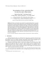
The water contact angles (CA) of the pristine and SAMs with
various chain lengths modified glass substrates are shown in
Fig. 1(a). The pristine glass substrate exhibited a hydrophilic
surface with a low contact angle of y10u, which can be
attributed to the generation of hydroxyl groups on the glass
surface due to UV/ozone treatment. However, the CA increased
drastically to over 90u upon the passivation of SAMs on the
glass substrates. Such a result is rational since hydrocarbon
species are hydrophobic. Moreover, the results showed that
the water CA increased with respect to the increase of
hydrocarbon chain length of SAMs. In general, the contact
angle is determined by the properties of surface functional
groups and not by the alkyl chain length. However, the alkyl
chain affects indirectly on the surface properties through
ordering, packing, and tilt of the SAM on substrates.35 The
critical surface tensions with respect to the pristine and
SAMs-modified glass were deduced by the Zisman plots as
demonstrated in Fig. 1(b), and their corresponding values
together with the CAs are revealed in Fig. 1(c). It was found
that the contact angles increased and the critical surface
tensions decreased with the increase in hydrocarbon chain
length of alkylsilane SAMs. Since all SAMs have no functional
group other than –CH3 in our study, it is assured that
passivation of various SAMs on glass only varies their surface
energies without changing the surface dipole moment.
Paper CrystEngComm
Published on 22 July 2013. Downloaded by National Taiwan University of Science and Technology on 08/08/2013 11:21:09.
</div>
<span class='text_page_counter'>(3)</span><div class='page_container' data-page=3>
To investigate whether these SAMs grow well on glass or
not, we performed XPS analysis. The C 1s spectra featuring
SAMs with different chain lengths are demonstrated in Fig. S1
in the ESI.
3
The results revealed in Fig. 1(d) showed that thenormalized C 1s intensity of various alkylsilane SAMs
increased with the increment of carbon chain length of SAM
molecules, which confirmed that the SAMs were fabricated
well on glass. Moreover, the surface morphologies of the
pristine and SAMs modified glass were investigated using
AFM, and the results are demonstrated in Fig. S2 in the ESI.
3
All SAMs modified glass substrates are flatter than the pristine
glass as they exhibited lower surface roughness (,2.0 nm).
This result is consistent with the previous report.36
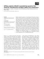
The XRD measurements of AZO deposited on substrates
with different surface energies are exhibited in Fig. 2. The
results revealed that all the obtained AZO films deposited on
pristine and various alkylsilane SAMs modified glass exhibited
a major peak located at 34.22u, corresponding to the (002)
plane. Other peaks exhibited at 31.45u, 36.05u, 47.30u, 56.41u,
62.53u and 67.58u correspond to (100), (101), (102), (110), (103),
and (112), respectively. This indicated that all the AZO films
were polycrystalline with a preferential c-axis growth
orienta-tion perpendicular to the substrate surface. The peak posiorienta-tion
of (002) orientation, observed at 2h = 34.22u, was lower than
that of the standard ZnO crystal (2h = 34.45u). The ionic radii of
Zn2+<sub>and Al</sub>3+<sub>are 72 and 53 pm, respectively, when Al atoms</sub>
are substituted into the Zn site in the crystal, the length of the
c-axis is expected to be shorter. However, the Al atoms might
not only substitute the Zn site in the ZnO lattice but also
occupy the interstitial sites of ZnO or segregate in the
non-crystalline region of the grain boundary to form Al–O bonds.37
It is noteworthy that the normalized intensity and the full
width at half maximum (FWHM) of the XRD peak at (002)
became stronger and narrower with respect to the increased
chain length of SAMs as shown in Table 1, indicating the
crystallinity of AZO films improved with the decrease in
surface energy of the substrates. The average crystallite size dg
was calculated by using Scherrer’s equation.38
dg~
Kl
B cos h
Where l is the X-ray wavelength (1.5406 Å), B is the FWHM and h
is the Bragg diffraction angle. It was found that the average
crystallite size increases with a decrease in surface energies of the
substrates as shown in Table 1.
The improved crystallinity and increased grain size of AZO
films upon the decrease of surface energies of the glass
substrates were possibly due to two reasons; first, it is well
Fig. 1 The chemical structures of alkylsilane molecules, and the water contact angles of the pristine and their SAMs modified glass substrates (a), Zisman plots for
calculating the critical surface energies of pristine glass, C3-SAM, C8-SAM, C12-SAM, and C18-SAM (b), the water contact angles and the critical surface energies of
pristine and different SAMs modified glass substrates (c), and the normalized C 1s area ratios of various SAMs on glass substrates (d).
</div>
<span class='text_page_counter'>(4)</span><div class='page_container' data-page=4>
known that to achieve good crystallinity of thin film deposition
on foreign substrates, a high temperature deposition or
post-annealing often compensate the surface energy of the
substrate, in order to increase the mobilities of deposited
atoms on the substrate surface.39However, with the assistance
of SAMs in our work, as the surface energies of glass substrates
were largely reduced, the deposited species might have enough
mobility even at room temperature. Second, since the SAMs
are mostly hydrocarbon, the wettabilities of AZO to SAMs are
poorer than that to bare glass surface. Therefore, the
nucleation rate of AZO on SAMs might be reduced since it is
less easy for AZO to ‘‘stick’’ on SAMs as compared to that on
the pristine substrate. As a result, the Avrami theory40,41can be
applied to interpret the increased grain size of AZO upon the
decrease in surface energies herein.
Moreover, from Fig. 2 and Table 1, it is evident that the
peak ratio of (100) to (002) orientations of the AZO films can be
manipulated through the modulation of surface energies.
With the decrease in surface energies, the peak area ratios of
(100) to (002) were found to be reduced. The peak area ratio of
(100)/(002) for AZO on pristine glass was 0.75, which
subsequently decreased to 0.35, 0.31 and 0.04 for the film
deposited on C-3, C-8, and C-12 SAM modified substrates,
respectively. It is noteworthy that for the AZO film deposited
on C18-SAM, the peaks (100) were found to disappear. Since
the peak (100) corresponding to the crystal growth along the
a-axis and (002) direction represent c-axis growth, the decrease
in (100) to (002) ratio suggested a transformation of the growth
direction of AZO with respect to the change of the substrate
surface energies.
SEM images were collected to determine the surface
morphologies and the thickness of AZO films deposited on
pristine and various alkylsilane SAMs modified glass
sub-strates. The thickness of each film was summarized in Table 1.
All films are in the range of 660–720 nm and the film thickness
reduced with respect to the increase in the chain length of the
SAM molecules, possibly due to the different sticking
coefficients of AZO to different substrates. Fig. 3(a)–(i) reveals
the morphologies of AZO films deposited on bare glass,
C3-SAM and C18-C3-SAM modified glass substrates at different
deposition times while the corresponding images of C8- and
C12-SAMs are demonstrated in Fig. S2 in the ESI.
3
The surfaceenergy of bare glass is about 74.4 mN m21, which is high
enough to make the AZO film ‘‘wet’’ the substrate surface and
thus exhibited a layer plus island growth mode (intermediate
Stransi–Krastanov mode) in which partial two-dimensional
layers are formed with some three-dimensional islands. When
the glass substrates were modified by various alkylsilane
SAMs, the surface energies of the substrates decreased.
Therefore, the AZO did not wet the substrates. Instead, they
first tend to be clustered upon the deposition to form the
rod-like structure and grow in a lateral direction to increase the
rod diameter. Such behavior was referred to as islands growth
mode (Volmer–Weber mode). As a result, the crystal size
became larger with the decrease in surface energies. Moreover,
the changes in growth mode was a possible cause that led to
the changes of preferential growth orientation. As a
conse-quence, the (002) peak intensity increased with respect to the
Fig. 2 XRD patterns of AZO films deposited on pristine and various SAMs
modified glass substrates.
Table 1 The parameters of AZO films deposited on pristine and various SAMs modified glass substrates obtained with XRD, XPS, and SEM
AZO thin films
Film thickness
(nm)
Normalized (002)
peak intensitya FWHM (u) Grain size (nm)
Peak ratio of
(100)/(002) Al in Al2O3/total Alb
AZO/glass 714 1.00 0.5 16.63 0.75 0.60
AZO/C3-SAM/glass 698 1.81 0.42 19.79 0.35 0.28
AZO/C8-SAM/glass 694 1.86 0.39 21.31 0.31 0.26
AZO/C12-SAM/glass 683 2.70 0.35 23.75 0.04 0.20
AZO/C18-SAM/glass 666 2.87 0.32 25.97 0 0.17
a<sub>Normalized to AZO film thickness.</sub>b<sub>Obtained from Al 2p XPS spectra.</sub>
Paper CrystEngComm
Published on 22 July 2013. Downloaded by National Taiwan University of Science and Technology on 08/08/2013 11:21:09.
</div>
<span class='text_page_counter'>(5)</span><div class='page_container' data-page=5>
decrease in surface energies, which confirmed the XRD results
in Table 1.
It is noteworthy that at the initial stage (1 min) the pristine
substrate exhibited no crystal structure of AZO on the surface
as shown in Fig. 3(a). In sharp contrast, small grains can
already been observed on C18-SAM modified glass at 1 min
deposition time (Fig. 3(c)). Moreover, the crystal growth rate
increases with respect to the decrease of surface energy as can
be observed evidently in Fig. 3.
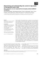
In order to examine whether Al3+ <sub>in Al</sub>
2O3was substituted
into the ZnO lattice or segregated at the boundary, the
chemical states of the AZO at the initial stage (AZO films
deposition time = 30 s) were investigated with XPS and the
results are shown in Fig. 4. The XPS spectra of the Al 2p core
level were deconvoluted into two components, which were
located aty73.3 eV and y74.2 eV, corresponding to Al–O in
AZO with an oxygen-deficiency in the ZnO matrix42and Al2O3
segregated at the grain boundaries, respectively. No peak of
metallic Al was observed at binding energy ofy72.7 eV.43<sub>The</sub>
ratio of Al in Al2O3 (y74.2 eV) to total Al were found to be
decreased with respect to the increment of hydrocarbon chain
lengths of alkylsilane SAMs (Table 1), indicating that the
amount of Al3+ion segregated at the grain boundaries of AZO
was less with the decrease in substrate surface energies;
possibly due to the reason that the grain size of AZO increased
with respect to the decrease in substrate energy. Therefore, the
total areas of grain boundary decreased, and thus, decreased
the possibility for Al3+to segregate at grain boundaries.
The Hall measurements were performed with the
utiliza-tion of the van der Pauw method to investigate the electrical
properties of AZO films deposited on pristine and various
SAMs modified surfaces. The results are summarized in
Table 2. It is clear that the resistivity of AZO films decreased
with the reduction of the surface energies of glass substrates
due to the increased carrier mobility. Decrease in substrate
surface energy resulted in better crystallinity, increased grain
size and less Al3+segregation of the AZO film, which allowed a
decrease in carrier scattering in the film area that to be crossed
by the electrons. Therefore, it led to an increase in Hall
mobility and film conductivity.44 <sub>Moreover, the reduction of</sub>
surface energies could contribute to the increasing amount of
Al3+substituted to Zn2+in the ZnO lattice as revealed in Fig. 4,
which might reduce the defects in the ZnO lattice that resulted
in the improvement of Hall mobility as well.
For optical properties, we performed UV-Vis transmittance
measurements, and the results are revealed in Fig. 5. It is
cleared that the average transmittance over the 400–800 nm
range exceeds 85% for all AZO films deposited on SAMs
modified glass substrate regardless of the surface energies,
which meets the requirement for a transparent conducting
oxide to be applied practically in a device. The transmittance
of AZO films deposited on SAMs modified glass substrate was
slightly improved, compared to AZO film deposited on pristine
substrate, possibly due to the improved crystallinity of AZO
films on SAMs modified glass.
Fig. 3 SEM images of AZO films deposited at different deposition times 1, 5 and
60 minutes on pristine ((a), (d), and (g)), C3-SAM ((b), (e), and (h)), and C18-SAM
((c), (f), and (i)) modified glass substrates.
Fig. 4 Al 2p XPS spectra of AZO films deposited on various SAMs modified glass
substrates.
</div>
<span class='text_page_counter'>(6)</span><div class='page_container' data-page=6>
The bandgap of each AZO film can be deduced from UV-Vis
spectra as shown in the inset in Fig. 5. All films revealed
bandgap values between 3.3 and 3.4 eV (Table S1 in ESI
3
),which is rational for AZO films. A trend can be observed that
the bandgap decreased slightly upon the decrease of the chain
length of the SAMs. It is possible due to the reason that the
crystallinity diminished with the decrease of alkyl chain
length, leading to the increased defect of the AZO film.
Thus, the Fermi level of the AZO is altered, resulting in the
reduction of bandgap.
Summary
In summary, we demonstrated the utilization of SAMs with
different hydrocarbon chain lengths on glass substrates, to
modulate the surface energies and the effect on AZO films
deposited on those substrates thereafter. With decrease in
surface energies, not only the crystallinity and the grain sizes
of AZO films improved, but also the amount of Al3+ ion,
substituted into Zn2+ ion sites in the ZnO lattice were
increased, resulting in amplification of Hall mobility and
decrease in resistivity of AZO films. Furthermore, the surface
energy manipulated the growth mode and the orientations of
the AZO film. Our study paves a way for the manipulation of
oxide thin film structures and properties at room temperature
without heating, which is crucial for the applications in
flexible optoelectronics where the substrates are sensitive to
heat.
Acknowledgements
The authors are grateful to Prof. Thomas C.-K. Yang of NTUT
for the support of XRD instrumentation. This work was
financially supported by the National Science Council.
References
1 H. Kim, C. M. Gilmore, J. S. Horwitz, A. Pique, H. Murata,
G. P. Kushto, R. Schlaf, Z. H. Kafafi and D. B. Chrisey, Appl.
Phys. Lett., 2000, 76, 259–261.
2 S. H. Jeong and J. H. Boo, Thin Solid Films, 2004, 447–448,
105–110.
3 L. Kerkache, A. Layadi and A. Mosser, J. Alloys Compd.,
2009, 485, 46–50.
4 S. H. Paeng, M. W. Park and Y. M. Sung, Surf. Coat.
Technol., 2010, 205, S210–S215.
5 J. G. Lu, Z. Z. Ye, Y. J. Zeng, L. P. Zhu, L. Wang, J. Yuan, B.
H. Zhao and Q. L. Liang, J. Appl. Phys., 2006, 100,
073714–11.
6 M. Chen, Z. L. Pei, C. Sun, L. S. Wen and X. Wang, Mater.
Lett., 2001, 48, 194–198.
7 M. Purica, E. Budianu, E. Rusu, M. Danila and R. Gavrila,
Thin Solid Films, 2002, 403–404, 485–488.
8 V. Khranovskyy, J. Eriksson, A. Lloyd-Spetz, R. Yakimova
and L. Hultman, Thin Solid Films, 2009, 517, 2073–2078.
9 S. Y. Myong and K. S. Lim, Appl. Phys. Lett., 2003, 82,
3026–3028.
10 R. Wen, L. Wang, X. Wang, G. H. Yue, Y. Chen and D.
L. Peng, J. Alloys Compd., 2010, 508, 370–374.
11 D.-K. Kim and H.-B. Kim, J. Alloys Compd., 2012, 522,
69–73.
12 M. Suchea, S. Christoulakis, N. Katsarakis, T. Kitsopoulos
and G. Kiriakidis, Thin Solid Films, 2007, 515, 6562–6566.
13 Y. E. Lee, Y. J. Kim and H. J. Kim, J. Mater. Res., 1998, 13,
1260–1265.
14 V. Srikant, V. Sergo and D. R. Clarke, J. Am. Ceram. Soc.,
1995, 78, 1935–1939.
15 W.-H. Kim, W. J. Maeng, M.-K. Kim and H. Kim, J.
Electrochem. Soc., 2011, 158, D495–D499.
16 H. Sato, T. Minami, S. Takata, T. Miyata and M. Ishii, Thin
Solid Films, 1993, 236, 14–19.
Table 2 The electrical parameters of AZO films deposited on pristine and various SAMs modified glass substrates
AZO thin films Carrier concentration (61020<sub>cm</sub>23<sub>)</sub> <sub>Mobility (cm</sub>2<sub>V</sub>21<sub>s</sub>21<sub>)</sub> <sub>Resistivity (10</sub>23<sub>V cm)</sub> <sub>Sheet resistance (V)</sub>
AZO/glass 2.28 2.72 10.08 141.2
AZO/C3-SAM/glass 2.31 3.24 8.35 120.3
AZO/C8-SAM/glass 2.18 3.48 8.24 118.3
AZO/C12-SAM/glass 2.46 3.76 6.76 99.0
AZO/C18-SAM/glass 2.27 4.19 6.57 98.6
Fig. 5 The transmittance of AZO thin films deposited on pristine and various
SAMs modified glass substrates.
Paper CrystEngComm
Published on 22 July 2013. Downloaded by National Taiwan University of Science and Technology on 08/08/2013 11:21:09.
</div>
<span class='text_page_counter'>(7)</span><div class='page_container' data-page=7>
17 M. Ohyama, H. Kozuka and T. Yoko, J. Am. Ceram. Soc.,
1998, 81, 1622–1632.
18 D. Ravindra and J. K. Sharma, J. Appl. Phys., 1985, 58,
838–844.
19 A. F. Aktaruzzaman, G. L. Sharma and L. K. Malhotra, Thin
Solid Films, 1991, 198, 67–74.
20 H. M. Zhou, D. Q. Yi, Z. M. Yu, L. R. Xiao and J. Li, Thin
Solid Films, 2007, 515, 6909–6914.
21 J.-M. Kim, P. Thiyagarajan and S.-W. Rhee, Thin Solid Films,
2010, 518, 5860–5865.
22 D. P. Norton, Mater. Sci. Eng., R, 2004, 43, 139–247.
23 J. H. Lee and J. T. Song, Thin Solid Films, 2008, 516,
1377–1381.
24 M. Chen, Z. L. Pei, X. Wang, C. Sun and L. S. Wen, Mater.
Lett., 2001, 48, 137–143.
25 S.-Y. Kuo, K.-C. Liu, F.-I. Lai, J.-F. Yang, W.-C. Chen,
M.-Y. Hsieh, H.-I. Lin and W.-T. Lin, Microelectron. Reliab.,
2010, 50, 730–733.
26 X. B. Zhang, Z. L. Pei, J. Gong and C. Sun, J. Appl. Phys.,
2007, 101, 014910–7.
27 J. W. Seong, K. H. Kim, Y. W. Beag, S. K. Koh and K.
H. Yoon, J. Vac. Sci. Technol., A, 2004, 22, 1139–1145.
28 D. K. Kim and H. B. Kim, J. Alloys Compd., 2011, 509,
421–425.
29 Y. Tai, J. Sharma, H.-C. Chang, T. V. T. Tien and
Y.-S. Chiou, Chem. Commun., 2011, 47, 1785–1787.
30 N. Rozlosnik, M. C. Gerstenberg and N. B. Larsen,
Langmuir, 2003, 19, 1182–1188.
31 A. Ulman, Chem. Rev., 1996, 96, 1533–1554.
32 N. Ballav, A. Terfort and M. Zharnikov, J. Phys. Chem. C,
2009, 113, 3697–3706.
33 A. Singh, I. S. Lee, K. Kim and A. S. Myerson,
CrystEngComm, 2011, 13, 24–32.
34 W. A. Zisman, Relation of the equilibrium contact angle to
liquid and solid constitution, in Contact Angle, Wettability,
and Adhesion, American Chemical Society, Washington,
DC, 1964, vol. 43, pp. 1–51.
35 D. K. Aswal, S. Lenfant, D. Guerin, J. V. Yakhmi and
D. Vuillaume, Anal. Chim. Acta, 2006, 568, 84–108.
36 Y. Wang and M. Lieberman, Langmuir, 2003, 19,
1159–1167.
37 K. C. Park, D. Y. Ma and K. H. Kim, Thin Solid Films, 1997,
305, 201–209.
38 B. D. Cullity, Elements of X-ray Diffraction, Addison-Wesley,
2nd, 1978, p. 102.
39 J. A. Venables, G. D. T. Spiller and M. Hanbucken, Rep.
Prog. Phys., 1984, 47, 399–459.
40 M. Avrami, J. Chem. Phys., 1939, 7, 1103.
41 M. Avrami, J. Chem. Phys., 1940, 8, 212.
42 M. Chen, X. Wang, Y. H. Yu, Z. L. Pei, X. D. Bai, C. Sun, R.
F. Huang and L. S. Wen, Appl. Surf. Sci., 2000, 158, 134–140.
43 C. D. Wagner, L. E. Davis, J. F. Moulder and G.
E. Muilenberg, Handbook of X-ray Photoelectron
Spectroscopy, PerkinElmer Corporation, Eden Prairie, Mn,
1979, pp. 50–51.
44 Y. Yang, X. Zeng, Y. Zeng, L. Liu and Q. Chen, Appl. Surf.
Sci., 2010, 257, 232–238.
</div>
<!--links-->
Control of Cell Proliferation and Growth byMyc Proteins
- 14
- 376
- 0


.push({});</script> </div> </div> </div> <div class="vf_link_relate px-2 my-2"> <h2 class="vf_doc_relate text-2xl font-bold my-4">Tài liệu liên quan</h2> <ul class="grid grid-cols-12 gap-2"> <li class="col-span-6 md:col-span-2"> <div class="card-doc " onclick="actionDocRelated(this)"> <a class="card-doc-img" href="https://text.123docz.net/document/709278-control-of-cell-proliferation-and-growth-bymyc-proteins.htm" title="Control of Cell Proliferation and Growth byMyc Proteins"> <i class="icon i_type_doc i_type_doc2"></i> <img class="lazy" src="data:image/gif;base64,R0lGODlhAQABAIAAAP///wAAACH5BAEAAAAALAAAAAABAAEAAAICRAEAOw==" data-src="https://media.store123doc.com/images/document/13/to/ue/medium_ZYEXS4N8Ec.jpg" width="124" height="179" alt="Control of Cell Proliferation and Growth byMyc Proteins" onerror="this.src=)