Modeling, Measurement and Control P23
Bạn đang xem bản rút gọn của tài liệu. Xem và tải ngay bản đầy đủ của tài liệu tại đây (3.45 MB, 52 trang )
23
Control of
Robotic Systems in
Contact Tasks
23.1 Introduction
23.2 Contact Tasks
23.3 Classification of Robotized Concepts for
Constrained Motion Control
23.4 Model of Robot Performing Contact Tasks
23.5 Passive Compliance Methods
Nonadaptable Compliance Methods • Adaptable
Compliance Methods
23.6 Active Compliant Motion Control Methods
Impedance Control • Hybrid Position/Force Control •
Force/Impedance Control • Position/Force Control
of Robots Interacting with Dynamic Environment
23.7 Contact Stability and Transition
23.8 Synthesis of Impedance Control at Higher
Control Levels
Compliance C-Frame • Operating Modes • Change
of Impedance Gains — Relax Function • Impedance
Control Commands • Control Algorithms • Implicit
Force Control Integration
23.9 Conclusion
23.1 Introduction
This chapter reviews the state of the art of the control of compliant motion. It covers early ideas and
later improvements, as well as new control concepts and recent trends. A comprehensive review of
various compliant motion control methods proposed in the literature would certainly be voluminous,
since the research in this area has grown rapidly in recent years. Therefore, for practical reasons, a
limited number of the most relevant or representative investigations and methods are discussed. Before
we review the results, we categorize compliant motion tasks and proposed control concepts based on
various classifying criteria. Particular attention is paid to traditional indices of control performance and
to the reliability and applicability of algorithms and control schemes in industrial robotic systems.
23.2 Contact Tasks
Robotic applications can be categorized in two classes based on the nature of interaction between
a robot and its environment. The first one covers
noncontact
, e.g., unconstrained, motion in a free
Dragoljub S
ˇ
urdilovi´c
Fraunhofer Institute
Miomir Vukobratovi´c
Mihajlo Pupin Institute
8596Ch23Frame Page 587 Friday, November 9, 2001 6:26 PM
© 2002 by CRC Press LLC
space, without environmental influence exerted on the robot. The robot’s dynamics have a crucial
influence upon its performance of noncontact tasks. A limited number of frequently performed simple
robotic tasks such as pick-and-place, spray painting, gluing, and welding, belong to this group.
In contrast, many advanced robotic applications such as assembly and machining require the
manipulator to be mechanically coupled to the other objects. In principle, two basic
contact task
subclasses can be distinguished. The first one includes
essential force tasks
whose nature requires
the end effector to establish physical contact with the environment and exert a process-specific
force. In general, these tasks require the positions of the end effector and the interaction force to
be simultaneously controlled. Typical examples of such tasks are machining processes such as
grinding, deburring, polishing, and bending. Force is an inherent part of the process and plays a
decisive role in task fulfillment (e.g., metal cutting or plastic deformation). In order to prevent
overloading or damage to the tool during operation, this force must be controlled in accordance
with some definite task requirements.
The prime emphasis within the second subclass lies on the requirement for end effector motion
near the constrained surfaces (
compliant motion
). A typical representative task is the part mating
process. The problem of controlling the robot during these tasks is, in principle, the problem of
accurate positioning. However, due to imperfections inherent in the process and the sensing and
control system, these tasks are inevitably accompanied by contact with constrained surfaces, which
produces reaction forces. The measurement of interaction force provides useful information for
error detection and allows appropriate modification of the prescribed robot motion.
Future research will certainly develop more tasks for which interaction with the environment
will be fundamental. Recent medical robot applications (e.g., spine surgery, neurosurgical and
microsurgical operations, and knee and hip joint replacements) may also be considered
essential
contact tasks
. Comprehensive research programs in automated construction, agriculture, and food
industry focus on the robotization of other types of contact tasks such as underground excavation
and meat deboning.
Common to all contact tasks is the presence of the constraints upon robot motion due to
environmental objects. If all parameters of the environment and robot were known and robot
positioning was precise, it might be possible to accomplish the majority of these tasks using the
same control strategies and techniques developed for the control of robot motion in free space.
However, none of these conditions can be fulfilled in reality. Hence, contact tasks are characterized
by the dynamic interaction between robot and environment, which often cannot be predicted
accurately. The magnitude of the mechanical work exchanged between the robot and the environ-
ment during contact may vary drastically and cause significant alteration of performance of the
robotic control system. Therefore, for successful completion of contact tasks, the interaction forces
have to be monitored and controlled, or control concepts ensuring the robot interacts compliantly
with the environment must be applied.
Compliance
, i.e., accommodation,
1
can be considered a measure of the ability of a manipulator
to react to interaction forces. This term refers to a variety of control methods in which the end
effector motion is modified by contact forces.
23.3 Classification of Robotized Concepts for Constrained
Motion Control
The previous classification of elementary robotic tasks provides a framework for the further
systematization of compliant motion control. Recently, the problems encountered in the control of
compliant motion have been extensively investigated and several control strategies and schemes
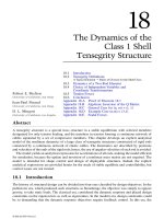
have been proposed. These methods can be systematized according to different criteria. The primary
systematization requires considering the kind of compliance. According to this criterion, two basic
groups of control concepts for compliant motion are distinguishable (Figure 23.1):
8596Ch23Frame Page 588 Friday, November 9, 2001 6:26 PM
© 2002 by CRC Press LLC
1.
Passive compliance,
whereby the position of the end effector is accommodated by the contact
forces due to compliance inherent in the manipulator structure, servos, or special compliant
devices.
2.
Active compliance,
whereby the compliance is provided by constructing a force feedback in
order to achieve a programmable robot reaction, either by controlling interaction force*
or
by generating task-specific compliance at the robot end point.
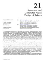
Regarding the possibility of adjusting system compliance to specific process requirements,
passive compliance methods can be categorized as
adaptable
and
nonadaptable
. Based on the
dominant sources of compliance, two methods within these groups can be distinguished
(Figure 23.2):
1. Fixed (or nonadaptable) passive compliance:
a. Methods based on the inherent compliance of the robot’s mechanical structure, such as
elasticity of the arm, joints, and end effectors.
2
b. Methods that use specially constructed passive deformable structures attached near the
end effectors and designed for particular problems. The best known is the remote center
compliance (RCC) element.
3
2. Adaptable passive compliance:
a. Methods based on devices with tunable compliance.
4
b. Compliance achieved by the adjustment of joint servo-gains.
5
The basic classification of
active compliance
control methods is based on the classifying tasks
as
essential
or
potential
. Using the terminology of bond–graph formalisms, robot behavior that
performs
essential contact tasks
can be generalized as a source of
effort
(force) that should raise
FIGURE 23.1
Basic classification of robot compliance.
FIGURE 23.2
Passive compliance classification.
*By
force
we mean
force and torque
and, accordingly,
position
should be interpreted as
position and orientation.
8596Ch23Frame Page 589 Friday, November 9, 2001 6:26 PM
© 2002 by CRC Press LLC
a
flow
(motion) reaction by environmental objects. The robot behavior associated with the second
or
potential
subclass corresponds to
impedance,
characterized by the reaction of robot’s motion
on external forces exerted by the environment. The active control force method can be classified
into two groups:
1.
Forc e
, i.e.,
position/force control
or
admittance control
, whereby both desired interaction
force and robot position are controlled. A desired force trajectory is commanded and force
measurements are required to realize feedback control.
2.
Impedance control,
6
uses the different relationships between acting forces and manipulator
position to adjust the mechanical impedance of the end effector to external forces. Impedance
control can be defined as allowing interaction forces to govern the error between the nominal
and actual positions of the end effector according to the target impedance law. Impedance control
is based on position control and requires position commands and measurements to close the
feedback loop. Force measurements are needed to effect the target impedance behavior.
Position/force control
methods can be divided into two categories:
1.
Hybrid position/force control
, whereby position and force are controlled in a nonconflicting
way in two orthogonal subspaces defined in a task-specific frame (
compliance
or
constraint
frame
). For force-controlled end-effector degrees of freedom (DOF), the contact force is
essential for performing the task. The motion is most important in position DOF. Force is
commanded and controlled along directions constrained by the environment, while position
is controlled in directions in which the manipulator is free to move (
unconstrained
).
Hybrid
control
is usually referred to as the method of Raibert and Craig.
7
However, according to
Mason’s
1
definition, this term is used in a more general sense and is defined as any controller
based on the division into force and position controlled directions.
2.
Unified position/force control,
which
differs essentially from the above conventional hybrid
control schemes.Vukobratovi´c and Ekalo
8,33
have established a dynamic approach to simul-
taneously control both the position and force in an environment with completely dynamic
reactions. The approach of dynamic interction control
8,33
defines two control subtasks respon-
sible for stabilization of robot position and interaction force. Both control subtasks utilize a
dynamic model of the robot and the environment in order to ensure the tracking of the
nominal motion and the force.
3.
Parallel position-force control,
9
is based on the appropriate tuning of the position and force
controllers. The force loop is designed to dominate the position control loop along constrained
task directions where a force interaction is expected. From this viewpoint, the parallel control
can be considered as impedance/force control.
Taking into account the way in which the force information is included in the forward control
path, the following position/force control schemes can further be distinguished:
1.
Explicit
or
force-based
7,10,11
whereby force control signals (i.e., the difference between the
desired and actual forces) are used to generate the torque inputs for the actuators in the joints.
2.
Implicit
or
position-based
algorithms
12,13
whereby the force control error is converted to an
appropriate motion adjustment in force-controlled directions and then added to the positional
control loop.
Impedance control methods can also be distinguished by the way the robotic mechanism is
treated: either as an actuator (i.e., source) of position or as an actuator of a force. The aim in
impedance control is to provide specific relationships between effort and motion rather than
follow a prescribed force trajectory as in the case of force control. Considering the arrangement
of position and force sensor and control signals within control loops (inner or outer), the following
two common approaches to provide task-specific impedance via feedback control can be distin-
guished:
14
8596Ch23Frame Page 590 Friday, November 9, 2001 6:26 PM
© 2002 by CRC Press LLC
1.
Position mode
or
outer loop control,
whereby a target impedance control block relating the
force exerted on the end effector and its relative position is added within an additional control
loop around the position-controlled manipulator. An inner loop is closed based on the position
sensor and an outer loop is closed around it based on the force sensor.
15,16
2.
Force mode
or
inner loop
control, whereby position is measured and force command is
computed to satisfy target impedance objectives.
14
Regarding the force–motion relationship or the impedance order, impedance control
schemes
can be further categorized into:
stiffness control,
17
damping control
,
18
and
general impedance
control,
19,20
using zeroth, first, and second order impedance models respectively.
There are additional criteria that allow further classification of active compliant motion control
concepts. For example, we can distinguish the methods with respect to the
source of force infor-
mation
(with or without direct interaction force sensing), and the
allocation of force sensor
(wrist,
torque sensor in joints, force-sensing pedestal, force sensor at the contact surface, sensors at robot
links, fingers, etc.). To avoid the problems associated with noncollocation between measurement
of contact forces and actuation in robot joints, which can cause instability,
21
the use of redundant
force information combining joint force sensing with one of the above force sensing principles was
proposed.
Regarding the space in which the active force control is performed in, one can distinguish between
two methods:
1.
Operational space control
techniques where control takes place in the same frame in which
actions are specified.
22,23
This approach requires the construction of a model describing the
system dynamic behavior as perceived at the end effector where the task is specified (oper-
ational point, i.e., coordinate frame). The traditional approach for specifying compliant
motion uses a
task
or
compliance frame
approach.
1
This geometrical approach introduces a
Cartesian-compliant frame with orthogonal force and position (velocity)-controlled direc-
tions. To overcome the limitations of this approach, new methods were proposed.
24,25
These
approaches, referred to as
explicit
task specification of compliant motion
, are based on the
model of the constraint topology for every contact configuration and utilize projective
geometry metrics to define a hybrid contact task.
2.
Joint space control
, whereby control objectives and actions are mapped into joint space.
26
Associated with this control approach are transformations of action attributes, compliance,
and contact forces from the task into the joint space.
Further, considering control issues, such as variations of control parameters (gains) during
execution, one can distinguish:
1.
Nonadaptive
active compliance control algorithms that use fixed gains assuming small
variations in the robot
and
environment parameters
2.
Adaptive control
, which can adapt the variation of process
27,28
3.
Robust control
approaches, which maintain model imprecision and parametric uncertainties
within specified bounds
29,30
Depending on the extent to which system dynamics is involved in the applied control laws, it is
possible to further distinguish:
1.
Nondynamic
, i.e.,
kinematic model-based
algorithms, such as
hybrid control
,
7
stiffness con-
trol,
17
etc., which approximate the contact problem considering its static aspects only.
2.
Dynamic model-based
control schemes, such as
resolved acceleration control,
31
dynamic
hybrid control,
11
constrained robot control,
32
and
dynamic force-position control in contact
with dynamic environment,
8,33
based on complete dynamic models of the robot and the
environment that take into account all dynamic interactions between position- and force-
controlled directions.
8596Ch23Frame Page 591 Friday, November 9, 2001 6:26 PM
© 2002 by CRC Press LLC
Although contact motion is characterized by relatively low velocities, high dynamic interaction
(i.e., exchange of energy) between a robot and its environment affects the control system signifi-
cantly and can jeopardize the stability of the control system.
34
Consequently, the role of both
dynamics, namely dynamics of the robot
35
and dynamics of the environment,
8,33
in the control of
compliant motion, becomes essential. Kinematic algorithms are mostly based on Jacobian matrix
computation, while the complexity of the dynamic methods is much greater.
36
The seminal hybrid control method proposed by Raibert and Craig
7
essentially provides a
quasistatic approach to compliance control based on an idealized simple geometric model of a
constrained motion task (Mason’s
constraint frame formalism
). With hybrid control, the dynamics
of both robot and environment (dynamic interaction) is neglected. The
dynamic hybrid control
11
and constrained motion control
32
approaches consider the constraints upon robot motion in the
form of algebraic equations defining a hyper surface. These methods take the robot dynamic model
and the model of the environment into account in order to synthesize dynamic control laws to
ensure admissible robot motion with the constraint and achieve desired interaction forces. Gener-
alization of the constrained motion problem leads to introducing active dynamic contact forces
(dynamic environment), also described by differential equations. In a dynamic environment, the
interaction forces are not compensated by constraint reactions; they produce active work on the
environment. Obviously, contact with a dynamic environment requires consideration of the complete
system dynamics involving robot and interaction models to obtain admissible robot motion and
interaction forces. The “pure dynamic” interaction without passive reaction was considered by
Vukobratovi´c and Ekalo in papers dedicated to the dynamic control of robots interacting with the
dynamic environment.
8,33,89–91
A suitable model structure has been proposed by De Luca and Manes
37
that handles a most general case in which purely kinematic constraints on the robot end-effector
live together with the dynamic interactions.
Although very inclusive, the above classification cannot encompass all of the proposed concepts to
date. Some approaches combine two or more methods categorized in distinct groups, and attempt to
use the benefits of both to offset disadvantages of single solution strategies. Such methods use compliant
motion control approaches that combine force and impedance control.
12,38
Some methods integrate
control mechanical system design.
39
This approach is based on micro–macro manipulator structures
that provide inherently stable and well-suited subsystems for high bandwidth active force control.
The terminology used above represents, in some measure, a trade-off among different nomen-
clatures used in the literature. Mason
1
designates the control concepts by specifying the linear
relation between effector force and position as explicit feedback, while Whitney
6
uses the phrase
explicit control to refer to techniques having a desired force input other than position or velocity
input. The classification and the terminology reflect, in our opinion, the essential aspects of
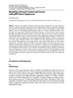
appropriate control strategies. The above classification is summarized in Figures 23.1 through 23.3.
23.4 Model of Robot Performing Contact Tasks
During the execution of a contact task, the kinematic structure of the robot changes from an open
to a closed chain. Contact with the environment imposes kinematic and dynamic constraints on the
motion of the end effector. One of the most difficult aspects of dynamic modeling concerns the
interactions of bodies in contact. We will briefly consider simplified models of constrained motion
to be used for the analysis of contact motion control concepts.
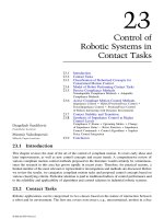
In order to form a mathematical model that describes the dynamics of the closed configuration
manipulator, let us consider an open robot structure whose last link (end effector) is subjected to
a generalized external force (Figure 23.4). A dynamics model of rigid manipulation robot interacting
with the environment is described by the vector differential equation in the form:
(23.1)
H(q)q h(q,q) g q J (q)F
˙˙ ˙
++
()
=+ττ
a
T
8596Ch23Frame Page 592 Friday, November 9, 2001 6:26 PM
© 2002 by CRC Press LLC
where is an n-dimensional vector of robot generalized coordinates; H(q) is an n × n positive
definite matrix of inertia moments of the manipulator mechanism; is an n-dimensional
nonlinear function of centrifugal and Coriolis moments; is a vector of gravitational moments;
is an n-dimensional vector of generalized joint axes driving torques; is an n × m
Jacobian matrix relating joint space velocity to task space velocity; and is an m-dimensional
vector of external forces and moments acting on the end effector.
The dynamic model of the actuator (we confine discussion to robot manipulators driven by DC
motors) that drive the robot joints must be added to the above equations. It is convenient to adopt this
model in linear form. Taking into account that electric time constants of DC motors driving almost all
commercial robotic systems are very low, we shall adopt a second order model of actuators:
(23.2)
where is the output angle of the motor shaft after-reducer; is the gear ratio; is the inertia
of the motor actuator; is the viscous friction coefficient; is the control input to the i-th
FIGURE 23.3 Active compliance control methods.
FIGURE 23.4 Open kinematic chain exposed to an external force action.
qq()= t
h( )q,q
˙
g( )q
ττττ
aa
t= ( ) J( )q
FF()= t
nI q nbq n
i mi mi i mi mi ai i mi
22
˙˙ ˙
++=ττ
q
mi
n
i
I
mi
b
mi
τ
mi
8596Ch23Frame Page 593 Friday, November 9, 2001 6:26 PM
© 2002 by CRC Press LLC
actuator (i.e., motor torque); and where i denotes the local i-th subsystem. The torque produced
by the motor is proportional to the armature current, that is:
(23.3)
where is the torque constant. If we assume the stiffness in the joints (gears) to be infinite, the
relation between the coordinate of the mechanism coincides with the actuator coordinate .
The dynamic models of the actuators and mechanical parts of the robot are related by joint
torques (loads). If we substitute from (23.2) into (23.1) we get the entire model of the robotic
mechanism in joint coordinate space:
(23.4)
where:
(23.5)
and is 6 × 1 vector of input torques at the joint shaft (after-reducer):
The above dynamical model can be transformed into an equivalent form that is more convenient
for analysis and synthesis of a robot controller for contact tasks. When the manipulator interacts
with the environment, it is convenient to describe its dynamics in the space where manipulation
task is described, rather than in joint coordinate space (also termed configuration space). The end
effector position and orientation with respect to a reference coordinate system can be described by
a six-dimensional vector x. The reference system is chosen to suit a particular robot application.
Most frequently, a fixed coordinate frame attached to the manipulator base is considered as the
reference system. Using the Jacobian matrix, we can transform the dynamic models (23.4) from
the joint into the end effector coordinate system:
(23.6)
where relationships among corresponding matrices and vectors from Equations (23.1) and (23.6)
are given by the following equations:
(23.7)
τ
mi mi mi
ki=
k
mi
q
i
q
mi
τ
ai
HqBqh g J F(q) q,q q (q)
q
˙˙ ˙
(
˙
)()++ +=+
m
T
ττ
HHIHqq q
()
=
()
+=
()
+
mim
diag n I
i
()
2
B
mimi
diag n b= ()
2
ττ
q
ττ
q
=
[]
nn
m
m
T
11
66
ττ.... .
ΛΛµµττ()
˙˙
()
˙
(,
˙
)()xxxxxxB x p++ +=+F
ΛΛ
µµΛΛ
ττττ
(JHJ
BJBJ
Jh J
pJg
J
m
xq q
x
xx q qq x qq
xq
q
T
T
T
T
T
)()()()
() () ()
(,
˙
)()(,
˙
)()
˙
(,
˙
)
˙
() () ()
()
=
=
=−
=
=
−−
−−
−
−
−
q
q
q
1
1
q
8596Ch23Frame Page 594 Friday, November 9, 2001 6:26 PM
© 2002 by CRC Press LLC
The description, analysis, and control of manipulator systems with respect to the dynamic
characteristics of their end effectors are referred to as the operational space formulation.
22
Anal-
ogous to the joint space quantities, is the operational space inertia matrix, is the
vector of Coriolis and centrifugal forces, is the vector of gravity terms, and τ is the applied
input control force in the operational space.
The interaction force is influenced by robot motion and also by the nature of the environment.
Since mechanical interaction is generally very complex and difficult describe mathematically, we
are compelled to introduce certain simplifications and thus partly idealize the problem. In practice,
the interaction force F is commonly modeled as a function of the robot dynamics, i.e., end-effector
motion (position, velocity, and acceleration) and control input:
(23.8)
where d and denote sets of robot and environment model parameters, respectively. The following
general work environment models have been mostly applied in the literature for describing con-
strained motion: rigid hypersurface, dynamic environment, and compliant environment.
In contact with a rigid hypersurface, robot motion (i.e., surface penetration) is prevented in the
direction orthogonal to the surface. For maintaining the constraint, only an infinitesimal displace-
ment in the tangential hyperplane is allowed. Different models describing robot constrained motion
on a rigid hypersurface have been presented in Yoshikawa et al.
11
and McClamroch and Wang.
32
These models can be applied for simulation or control design, i.e., computation of control laws
ensuring the robot remains on the constraint manifold. However, the complexity of these models
is great. In the special case of a rigid plane, model decomposition is relatively simple and does not
require that computations are repeated for every step. In general, however, computing and integrat-
ing these models involves extensive computations and solutions of numerical problems.
If the environment does not possess displacements (DOFs) independent of the robot motion, the
mathematical model of the environment dynamics in the frame of robot coordinates can be described
by nonlinear differential equations:
8
(23.9)
where is a nonsingular n × n matrix; is a nonlinear n-dimensional vector function;
and is an n × n matrix with rank equal to n. The system (23.4-23.9) then describes the
dynamics of robot interaction with dynamic environment. We assume that all the mentioned matrices
and vectors are continuous functions of the arguments for the contact cases.
In operational space, the model of a pure dynamic environment has the form:
40
In effect, a general environment model involves geometrical (kinematic) constraints plus
dynamic constraints.
37
An example of such a dynamic environment is when a robot is turning a
crank or sliding a drawer. Dynamics is relevant for the robot motion and cannot be neglected.
However, the dynamic model of kinematic–dynamic constraints is rather complex and its com-
putation involves several difficulties. The crucial problem is the decomposition of DOFs, i.e.,
force and independent coordinate parameterization, which is not unique from a mathematical
viewpoint. Although in several elemental contact cases, the feasible model parameterization is
ΛΛ x
()
µµ xx,
˙
()
p x
()
F Fxxx dd=
()
,
˙
,
˙˙
,,,ττ
e
d
e
M( )q L( , ) S ( )F
T
qqq q
˙˙
˙
+=−
M( )q L( , )qq
˙
S()
T
q
M(x) (x x)
˙˙
˙
xl, F+=−
M
M
(x)
(x,x) (x)
=
=−
−−
−
JMJ
lJL Jq
() ()()
˙
() (,
˙
)
˙
()
˙
qqq
qqq q
T
T
1
8596Ch23Frame Page 595 Friday, November 9, 2001 6:26 PM
© 2002 by CRC Press LLC
obvious,
37
it is difficult to perform model parameterization in many practical contact tasks. Planning
and computing tools supporting automatic minimal parameterization of a dynamic constrained motion
problem based on task specification do not exist. Moreover, the differentiation of constraint equations
can lead to unstable numerical solutions, causing constraint violation in real-time simulations. By
introducing inaccuracy in the robot and environment (e.g., for robust control design purposes), the
problem becomes even more complicated.
For control design purposes, it is customary to utilize a linearized model of manipulator and
environment. The applicability of a linearized model in constrained motion control design, espe-
cially in industrial robotic systems, was demonstrated in Goldenberg
41
and S
ˇ
urdilovi´c.
42
Neglecting
nonlinear Coriolis and centrifugal effects due to relatively low operating velocities (rate lineariza-
tion) during contact, and assuming the gravitational effect to be ideally compensated for, we obtain
a linearized model around a nominal trajectory in Cartesian space in the form:
(23.10)
In passive linear environments, it is convenient to adopt the relationship between forces and
motion around the contact point in the form (linear elastic environment):
(23.11)
where denotes the end effector penetration through the surface defined by , x
e
represents
contact point locations, and M
e
, B
e
, and K
e
are inertial, damping, and stiffness matrices, respectively.
23.5 Passive Compliance Methods
According to the classifications presented above, we first review the compliant control methods
based on passive accommodation (with no actuator involved). Passive compliance is a concept
often used to overcome the problems arising from positional and angular misalignments between
the manipulator and its working environment.
23.5.1 Nonadaptable Compliance Methods
The passive compliance method, which is based on inherent robot structural elasticity, is more
interesting as a theoretical solution than a feasible approach. This method assumes that the com-
pliance of the mechanical structure has a determining effect on the compliance of the entire system.
However, this assumption is opposite to the real performance of commercial robotic systems which
are designed to achieve high positioning accuracy. Elastic properties of the arms are insignificant.
The dominant influence on a somewhat larger deflexion of the manipulator tip position is, in some
cases, joint compliance, e.g., due to reducer elasticity (harmonic drive) or compressibility of the
hydraulic actuator.
43
In practice, the mechanical compliance of the robotic structure can be utilized
for contact tasks purposes under very restricted conditions. The endpoint compliance is often
unknown and too complex to be modeled. Due to high stiffness levels, the accommodation range
within an acceptable contact force level is usually extremely small and without any practical values.
This method does not offer any possibility to adapt system compliance to the various task requirements.
The idea of utilizing flexible manipulator arms as an instrumented compliant system
2
is relatively new
and poses additional problems due to complex modeling and controlling of elastic robots.
The method based on mechanical compliance devices, in principle, also utilizes structural com-
pliance. The most influential source of multi-axis compliance in this case, however, is a specially
constructed device whose behavior is known and sufficiently repeatable. Relatively good perfor-
mances have been achieved, especially in the robotic assembly. Different types of such devices
x
0
ΛΛττ(x ) (x )
00
˙˙ ˙
()xB x x F
0
+=+
−= + +FMpBpKp
ee e
˙˙ ˙
p pxx=−
e
8596Ch23Frame Page 596 Friday, November 9, 2001 6:26 PM
© 2002 by CRC Press LLC
have been developed; the best known is the RCC (remote center compliance)
3
developed in the
Charles Stark Draper Laboratory. RCC is designed to make the workpiece rotate around a defined
center of compliance. The compliance center is a point at which application of a force causes only
translation, while a torque applied around an axis through this point will cause rotation of the workpiece
(Figure 23.5). A crucial feature of the RCC is that it consists of translational and rotational parts; this
combination allows lateral and angular errors to be accommodated independently.
RCC elements provide a simple and effective solution that permits fast and easy interfacing of
mechanical parts in spite of initial positioning errors. The main advantage is that a simple positional
controller can be applied, without any additional force sensor feedback or complex calculations.
However, an RCC element cannot be applied to tasks involving parts of lengths and weights. A
solution to this problem may be to design a set of compliance adapters that can be changed according
to the needs of specific tasks.
Instrumented Remote Center Compliance (IRCC)
44
represents an improvement of RCC which
provides the fast error absorption characteristic of RCC and the measurement characteristic of a
multi-DOF sensor. Contact force and deformation data can be used for task monitoring, calibration,
contour following, or positioning feedback.
23.5.2 Adaptable Compliance Methods
Further development of RCC has led to adaptable compliant devices
4
which enable the location
of the center of compliance to be automatically controlled to a prescribed extent in accordance
with parts of different lengths and weights. These devices are usually also instrumented to provide
information about end point deflections for robot control.
The controller gain adjustment method is based on the compliance of the robotic controller and
attempts to provide a universally programmable passive compliance at endpoints, by the relatively
simple adjustment of servo gains. The basic principle is to tune the positional servo gains to make
the robot behave as a linear six-dimensional spring in Cartesian space with programmable stiffness.
Therefore, taking into account the relationship between forces exerted upon the robot and its reaction
(stiffness-like behavior), the gain adjustment method was considered equivalent to the impedance
(i.e., stiffness) control.
The choice of Cartesian stiffness matrix is strongly dependent on the task specification. In the case
of part mating, for example, the elements of the stiffness matrix that relate force and motion in the
direction of insertion should be estimated sufficiently high so that axial force does not cause the insertion
to stop. Conversely, in lateral directions, the corresponding elements should be sufficiently low to
enable the peg to move easily as it encounters the chamfer. A strategy for systematic setting of Cartesian
stiffness in different phases of peg/hole assembly is proposed by Simons and Van Brussel.
5
FIGURE 23.5 Remote center compliance (RCC).
8596Ch23Frame Page 597 Friday, November 9, 2001 6:26 PM
© 2002 by CRC Press LLC
The basic gain adjustment control scheme is sketched in (Figure 23.6), where x
0
and q
0
are
nominal Cartesian and joint position vectors, respectively; denotes the inverse kinematic
transformation; q is the actual joint position; and is the computed gravitational torque. The
control torque is obtained according to:
(23.12)
where k
p
represents the joint stiffness matrix which should be tuned to ensure the arm will behave
with the desired stiffness K
S
. The relationship between the joint and Cartesian stiffness matrices
is given by:
(23.13)
where J(q) represents Jacobian matrix-relating velocities (i.e., forces) between a Cartesian frame
attached at the compliance center and the joint coordinate space. At the center of compliance, the
Cartesian stiffness matrix is diagonal, but corresponding joint stiffness k
P
is, according to
Equation (23.13), a fully symmetric matrix. This means that the joint stiffness matrix is highly
coupled and a position error in one joint will affect the commanded torque in all other joints.
Equation (23.12) represents the central formulation of active gain adjustment methods. Assuming
the static (gravitational) forces are exactly compensated for and dynamic forces due to slow
displacements are negligible, it is relatively easy to prove that the linearized robot-and-environment
model is always stable. Control adjustment allows us to adopt the location of center of compliance
(by the aid of Jacobian matrix ) and Cartesian stiffness (choosing ). However, although this
stiffness-like behavior could be theoretically adjusted on-line while running a task, we have classified
this method as passive compliance, because the compliant motion is performed in a purely passive
way by the action of external forces, rather than by force feedback as with active stiffness control.
While the adaptable passive compliance method provides a simple and flexible solution for many
compliant motion tasks (without requirements for force sensing and feedback), the aim of having
the entire robot structure behave loosely in some directions is difficult to achieve. This concept is
coupled with several problems. Most contemporary robotic systems cannot accurately achieve the
desired spring-like behavior. Several nonlinearities such as friction and backlash in mechanical
transmission and process frictional phenomena like jamming can destroy the stiffness force/position
causality. Furthermore, by setting very low control gains in some directions, the entire system is
made more sensitive to perturbations. Different disturbances and nonlinearities can affect perfor-
mance, and that can be extremely dangerous in some environments. Since integral control action
is not applied, all static effects such as gravitation must be completely compensated for.
All these factors make the performance of this control approach uncertain, thus imposing the
need to introduce additional sensor information to monitor task execution. Relevant improvements
FIGURE 23.6 Passive gain adjustment scheme.
fx
−
()
1
ˆ
g q
( )
ττ
q
ττ
qp
=−
()
+
()
kq q g
0
ˆ
q
kJKJ
KJkJ
p
p
=
=
−−
T
S
S
T 1
J K
S
8596Ch23Frame Page 598 Friday, November 9, 2001 6:26 PM
© 2002 by CRC Press LLC
can be achieved by including force sensor information in a rule-based assembly strategy,
5
or by
introducing an internal force feedback loop.
45
However, the simplicity of passive gain adjustment
is lost when these additional strategies are applied. An equivalent improvement in performance can
be achieved by applying a simple active force control concept.
The principle of adaptable control gains is more suitable for direct drive, multifingered, or wrist
hands. This method appears similar to those described above, which use special adaptable compliant
devices.
If the passive gain adjustment concept is used in industrial practice, one should consider that
conventional robotic systems are nonbackdriveable due to high gear ratios and Coulomb fric-
tion/stiction effects in joints. (The order of equivalent friction force in Cartesian space is about 10
2
N.) Hence, although compliant control is applied, a force exerted at the end effector will not cause
a corresponding detectable displacement in joints. Therefore, the method can be applied only in
manipulation tasks that permit large interaction forces. Due to relatively high costs and low
robustness of force sensors, though, there is increased interest on the part of industrial robot
manufacturers in appling this method in specific tasks such as handling of castings (e.g., the new
soft servo or soft float industrial robot control functions).
23.6 Active Compliant Motion Control Methods
The active compliance control methods best utilize reprogrammability of manipulation robots. This
is done by representing the manipulation robots’ main characteristic, that is, their ability to switch
from one production task to another.
23.6.1 Impedance Control
Whitney first reported use of force feedback control of a manipulator for impedance control.
6
Impedance control is a fundamental approach toward allowing a stiff industrial robot to interact
with the environment. Impedance control is mainly directed to contact tasks for which the control
of interaction force is not essential for successful task execution. These contact tasks, such as insert,
require a specific motion of the workpiece that adheres to external constraints in the presence of
possible contact with the environment (constrained or compliant robot motion).
These compliant motion tasks require solution of motion control problems. The objective of the
impedance control is to reduce contact impedance or stiffness of the position-controlled robot. This
is done by controlling dynamic reaction to the external contact forces (robot compliance) to
compensate for uncertainties and tolerances in the robot–environment location, while maintaining
acceptable force magnitudes. The interaction force between a robot and a fixed environment depends
on motion and target impedance. Under certain circumstances, impedance control may also be
applied to produce a desired force.
An impedance control task is specified in terms of desired motion trajectory and relationships
between position error and interaction force exerted at the end effector. To ensure successful
accomplishment of a constrained motion task, the commonly stiff robot position control behavior
must be replaced with a compliant target impedance model.
The objective of impedance control differs from the conventional control goals in the sense that
the main control issue is not to ensure tracking of a reference input signal (e.g., nominal position
or force). The aim is to produce a reference target model (target impedance) specifying the
interaction of robot and environment, i.e., the desired relationship between acting forces and robot
motion reaction (position error). A conventional control system is usually analyzed for its ability
to track standard input signals (e.g., step, ramp) within the allowed time. The main impedance
control performance specification, however, addresses the capability of achieving the target model.
The impedance control problem can be defined as designing a controller so that interaction forces
govern the error between desired and actual positions of the end effector. The control input
8596Ch23Frame Page 599 Friday, November 9, 2001 6:26 PM
© 2002 by CRC Press LLC
describing a desired target impedance relation may, in principle, have an arbitrary functional form,
but it is commonly adopted in the linear second order differential equation form describing the
simple six-dimensional decoupled mass–spring–damper mechanical system. The reason is that the
dynamics of a second order system is well understood. Lee and Lee
46
developed a control algorithm
referred to as generalized impedance control by introducing a higher order impedance relation
between position and force errors, which includes force derivatives.
In other words, impedance control is a general approach to contact task control in which the
robot behaves as a mass–spring–dashpot system whose parameters can be specified arbitrarily. This
can be achieved by feedback control using position and force sensing. The following control
objective should be obtained:
(23.14)
or in the s domain:
(23.15)
where is the target robot impedance in Cartesian space, x
0
describes the
desired position trajectory, x is the actual position vector, is the position control error, F is the
external force exerted upon the robot, and , , and are positive definite matrices that define
target impedance, where is the stiffness matrix, is the damping matrix, and is the inertia
matrix. The diagonal elements of these target model matrices describe the desired robot mechanical
behavior during contact.
One of the most common approaches for representation of robot and object positions is based
on coordinate frames. It is convenient to describe the robot impedance reaction to external forces
with respect to a frame, referred to as a compliance or C frame. Along each C frame direction, the
target model describes a mechanical system presented in (Figure 23.7) with the programmable
impedance (mechanical parameters); for simplicity, only spring elements are depicted. The model
describes a virtual spatial system consisting of mutually independent spatial mass–damper–spring
subsystems in six Cartesian directions. A corresponding decoupled physical system is difficult to
FIGURE 23.7 Target stiffness model in C frame.
FMxx Bxx Kxx MeBeKe=−+−+−=++
tt t ttt
(
˙˙ ˙˙
)(
˙˙
)( )
˙˙ ˙
00 0
FZxxZeMBKxx() ()( ) () ( )( )ss s ss=−==++−
ttttt0
2
0
ZMBK
t
sss()=++
ttt
2
e
M
t
B
t
K
t
K
t
B
t
M
t
8596Ch23Frame Page 600 Friday, November 9, 2001 6:26 PM
© 2002 by CRC Press LLC
realize (for example, by combining Cartesian linear axes and Cardan frames). Appropriate selection
of target impedance parameters along specific axes is required to achieve active impedance control.
The target impedance matrices can be selected to correspond to various objectives of the given
manipulation task.
14
Obviously, high levels of stiffness are required in the directions where the envi-
ronment is compliant and positioning accuracy is important. Low stiffness can be selected in directions
where small interaction forces must be maintained. Large values are specified when energy must
be dissipated, and is used to provide smooth transient system response during contact.
To assess how well a designed impedance controller meets the above control objective, it is
customary to specify performance criteria. A reasonable measure to express the performance of
the impedance control is the difference between the target model and real system behavior described
by robot motion and interaction forces.
47
Depending on which of these physical values is used to
characterize the system behavior (force or position), the impedance control error can be expressed
by means of force measure (force model error):
(23.16)
or by position measure (position model error):
(23.17)
where the target position deviation is obtained as the solution of the target model differential equation:
(23.18)
for the initial conditions: .
The computing of the model errors requires both force and the robot position to be measured.
The above defined control goal can be achieved using various control strategies. Impedance
control represents a strategy for constrained motion rather than a concrete control scheme. Various
control concepts and schemes were established for controlling the relation between robot motion
and interaction force.
One of the first approaches to impedance control was proposed by Whitney
18
(Figure 23.8). In
this approach known as damping or accommodation control, the force feedback is closed around
the velocity control loop. The interaction force is converted into a velocity modification command
by a constant damping coefficient K
F
. Using a simplified example of discrete time force control,
Whitney defined the condition for system stability during contact as:
(23.19)
FIGURE 23.8 Damping control.
B
t
M
t
e Mxx Bxx Kxx F
f
tt t
=−+−+−−(
˙˙ ˙˙
)(
˙˙
)( )
00 0
exx x
p
f
=− −
0
δ
FMx Bx Kx=++
t
f
t
f
t
f
δδδ
˙˙ ˙
Fxxtt
000
0
()
=
()
=; δδ
f
01<<TK K
f
e
8596Ch23Frame Page 601 Friday, November 9, 2001 6:26 PM
© 2002 by CRC Press LLC
where is the sampling period, is the force control gain (damping coefficient), and is the
stiffness of the environment. This condition implies that if is high, the product TK
f
must be
small. To avoid large contact forces, a very high sampling rate, i.e., small is required. Alternatively,
for contact with a very stiff object Whitney proposed introduction of a passive compliance in order
to achieve the equivalent environmental stiffness smaller (including the stiffness of the robot
structure, environment, sensor, etc.).
Salisbury
17
proposed modification of the end effector position in accordance with the interaction
force (Figure 23.9). This concept is based on a generalized stiffness formulation where
is a generalized displacement from a nominal commanded end effector position, and is a
six-dimensional stiffness matrix. Based on the difference between the desired and actual end
positions, a nominal force is computed and converted into joint torques using the transpose of the
Jacobian matrix. This force is then used to determine the torque error on each joint that is further
used to correct applied torque so that the desired force (i.e., stiffness) is maintained at the robot
hand. The requirements of the stiffness matrix elements and their designs for specific tasks are
considered in Whitney.
6
These impedance control schemes are simple and relatively easy to implement. However, the
achieved closed loop impedance behavior in the Cartesian space depends on robot configuration.
Obviously, to replace the nonlinear dynamic model with the linear time-invariant target system
(e.g., mass–damper–spring system) generally requires the control law to compensate for relevant
system nonlinearities (model-based dynamic control).
The most common impedance control concept was established by Hogan
19
who defined a unified
theoretical framework for understanding the mechanical interactions between physical systems.
This approach focuses on the characterization and control of dynamic interaction based on manip-
ulator behavior modification. In this sense, impedance control is an augmentation of position
control. The actions of the manipulator control and hardware and the interaction between a robot
and its environment are described by network analysis. The important issue is that the command
and control of a vector such as position or force is not enough to control the interaction between
systems (dynamic networks). The controller must also be able to command and control a relationship
between system variables. The proposed control design strategy is to adapt the robot behavior to
become the inverse of the environment. This means that if the environment behaves like admittance,
the impedance control should be applied and vice versa.
23.6.1.1 Force-Based Impedance Control
Most of the impedance control algorithms utilize the computed torque method to cancel nonlinearity
in robot dynamics in order to achieve linear target impedance behavior. This popular approach requires
computation of a complete dynamic model of constrained motion, which make its realization rather
FIGURE 23.9 Stiffness control.
T K
f
K
e
K
e
T
K
e
FKx=δ
δx K
8596Ch23Frame Page 602 Friday, November 9, 2001 6:26 PM
© 2002 by CRC Press LLC
complex. An important drawback of this approach is sensitivity to model uncertainties and parameter
variations. Performance improvements that can be achieved with algorithms in industrial robotics
are not in proportion to implementation efforts.
Hogan
48
proposed several techniques with and without force feedback for modulating the end
point impedance of a general nonlinear manipulator. Assuming the Cartesian dynamic model
perfectly matches the real system, Hogan proposed the following nonlinear control law:
(23.20)
be applied to reach a reasonable target impedance behavior in the ideal case in the form:
. (23.21)
The control scheme corresponding to the above control law is sketched in (Figure 23.10). A
distinction is made in the figure between the active force exerted by the robot ( ) and the reactive
external force ( ), which can be computed assuming a simple spring-like environmental model:
(23.22)
where is the stiffness of the environment. This control law essentially represents a nonlinear
control algorithm that combines the inverse control technique
49
(also known as computed torque
method and nonlinear decoupling) and force-based (inner loop) impedance control. In force-based
impedance control algorithms (Figure 23.10), an expected reference force is computed to satisfy
the desired impedance specification based on position error and target impedance
. The expected active force is compared with the actual force sensed by
the force sensor and a force error is computed. This error is further multiplied with inertia matrices
. Finally, the product is summed with dynamic compensation terms (Coriolis and gravitation
vectors) and feed-forward force to obtain Cartesian control force, which is further transferred
into the robot joint via the transposed Jacobian to get the actuator torque control inputs. It is
relatively easy to prove that the control law:
(23.23)
realizes the impedance control behavior specified in Equation (23.15).
The reason impedance control methods based on force control input cannot be suitably applied
in commercial robotic system lies in the fact that commercial robots are designed as positioning
FIGURE 23.10 Force-based dynamic impedance control.
ττµµ==
ˆ
()
˙
ˆ
(,
˙
)
ˆ
()ΛMKx xBxF p F
tt t
xx x
−
−− +
[]
++−
1
0
FMxBxK(xx)
0
=++ −
tt t
˙˙ ˙
F
F
FKxx F=−
()
=−
ee
K
e
FZxx
00
ss
()
=
()
−
()
t
F
0
ˆ
ΛM
t
−1
F
J
T
ττµµ==
ˆ
˙˙
()(
˙˙
)
ˆ
(,
˙
)
ˆ
()Λ xMKxxBxxF p F
00
0
1
+−+−+
[]
{}
++−
−
tt t
xx x
8596Ch23Frame Page 603 Friday, November 9, 2001 6:26 PM
© 2002 by CRC Press LLC
devices. In the above methods, the driving torque vector ensuring the desired target impedance
behavior has been computed and then multiplied by the transpose of the Jacobian matrix in order
to be realized around the actuated robot joints. However, the realization of computed torque is not
accurate in commercial robotic systems because the local servos are position controlled and there
is no force feedback with respect to the torques around the joints. Consequently, the realization of
desired torques is poor, since high friction and other nonlinearities in the transmission mechanisms
contribute significantly to the inaccuracy of current/torque causality. Because of these difficulties,
the implementation of force-based impedance control can be successfully performed only by a new
generation of direct-drive robots
50
with accurate joint torque controls. Force-based impedance
control requires a completely new control system.
23.6.1.2 Position Based Impedance Control
As mentioned above, force-based impedance control is mainly intended for robotic systems with
relatively good causality between joint and end effector forces, such as direct-drive manipulators.
In commercial robots, the effects of nonlinear friction in transmission systems with high gear ratios
significantly destroy this causality. Therefore, in commercial robotic systems, it is feasible to
implement only the position-mode impedance control by closing a force-sensing loop around
position controller. Position-based impedance control is most reliable and suitable for implemen-
tation in industrial robot control systems since no modification of a conventional positional con-
troller is required.
Two basic impedance control schemes with internal position controls can be distinguished.
51
The
first scheme is sketched in Figure 23.11. An inner position control loop is closed based on position
sensing; it is surrounded by a closed outer loop based on force sensing. The force loop is naturally
closed when the end effector encounters the environment. The outer loop includes a force feedback
compensator , basically representing admittance since its role is to shape the relation between
contact force and corresponding nominal position modifications . This block is imposed on the
system to regulate the force response to the commanded and actual motions according to the target
admittance .
Other control blocks in Figure 23.11 represent a common industrial robot position control system
involving the following transfer function matrices: , position control regulator; , robot plant;
and , environment. The position correction is subtracted from the nominal position and
the command input vector for the positional controller, referred to as reference position , is
computed. A good tracking of the reference position must be achieved by the internal position
controller. Assuming , the position error input to the position controller becomes:
. (23.24)
This means that the control system in Figure 23.11 utilizes the position-related impedance model
error (23.17) to achieve target impedance behavior. The impedance model error is fed forward
to the position controller in order to be nullified within internal position control loop. Since the
FIGURE 23.11 Position model-error impedance control.
G
F
∆x
f
Z
t
−1
G
r
G
s
G
e
∆x
F
x
0
x
r
GZ
Ft
=
−1
∆x
r
∆∆xxxx xxxxZFe
rr F t p
=−=− −=−− =
−
00
1
e
p
e
p
G
r
8596Ch23Frame Page 604 Friday, November 9, 2001 6:26 PM
© 2002 by CRC Press LLC
purpose of the system in (Figure 23.11) is to control position, it will be referred to as position
impedance model error control.
The second position-based impedance control structure is depicted in (Figure 23.12). This scheme
provides a generalization of the original scheme proposed by Maples and Becker
15
and is referred
to as outer/inner loop stiffness control. The control scheme consists of two parallel feedback loops
superimposed to the internal position control and closed using measurements from both the wrist
force sensor and position sensors. Analyzing the control scheme, it can be seen that the position
error is multiplied by the task-specific target impedance to provide
a nominal (reference) force , which corresponds to the target impedance behavior on the output.
The tracking of this force is realized by the next feedback loop closed on the sensed force . In
the ideal case, we have , describing the target behavior. Thus Figure 23.12 basically represents
a force control system with target impedance added to regulate the motion response to the interaction
force. Following the control flow, we see that the force error in this control scheme corresponds
to the previously defined force impedance model error (23.17):
(23.25)
Therefore, we will refer to the control system in Figure 23.12 as force model error impedance
control. Similarly, to the previous system (Figure 23.11), the model error Equation (23.25) is further
relayed to the internal control part in order to regulate this error to zero as time increases. However,
different from the position model error control in Figure 23.11, where the position model error is
eliminated by the internal position control, in the control system in Figure 23.12, the regulation of
the model error is realized by means of the compensator . In order to retain the internal position
control loop, the implicit force control structure is implemented by passing the force error
through the admittance filter , providing nominal path modification . The position correction
is further added to the Cartesian nominal position , and via reference position feeds forward
to the position servo. Obviously, to achieve as which ensures a steady state
position deviation corresponding to the target impedance (stiffness) model, the
regulator has to involve an integral control term.
This scheme was originally developed as a position-based realization of Salisbury’s stiffness
control algorithm.
17
In this seminal work,
15
block was a diagonal stiffness matrix that allowed
the user to specify compliance along Cartesian directions, while compensator was realized as
a pure integrator ensuring desired stiffness steady state.
Both control approaches utilize similar concepts to produce the target impedance model by
reducing the impedance model errors and to zero. Each approach has specific advantages
and disadvantages.
51
The -based scheme (Figure 23.11) is simpler and easier to implement. Under
some circumstances, this scheme allows different target impedances to be realized by setting the
FIGURE 23.12 Force model error-based impedance control.
exxx==−∆
00
GZ
tt
ss
()
=
()
F
0
F
FF
0
=
∆FF FGx x Fe=−= −
()
−=
00t
f
G
F
∆F
G
F
∆x
F
x
0
x
r
∆Fe=→
f
0 t → ∞
xx e
0
−
()
=
∞
∞
G
F
G
t
G
F
e
p
e
f
e
p
8596Ch23Frame Page 605 Friday, November 9, 2001 6:26 PM
© 2002 by CRC Press LLC
compensator to the target admittance, while the position controller undertakes feedback control.
This is similar to an open loop target impedance control. Conversely, in the force model error
control scheme (Figure 23.12), the target impedance is specified in the outer loop using block,
while the role of the internal loop compensator is to ensure the tracking of the selected model
using force feedback. The internal position control loop is retained to achieve robust position-based,
i.e., implicit, force control and control robot motion in the free space. This scheme offers more
possibilities to adjust the system contact behavior by choosing and tuning . However, the
opportunity to arbitrarily select the target model and dynamically maintain the force/motion rela-
tionship is limited by the complex structure of this scheme.
The main problem with the -based scheme lies in the transition to and from contact (constrained
motion). The external impedance loop in this scheme is closed even in the free space when the
contact force is zero, and thus affects position control performance. Although the magnitude of the
position deviation can be insignificant, considering that the stiffness of the position control is
essentially greater than the target one and the inner position loop is faster than the external
impedance loops, this effect is not desirable in practice. The compensator has to be tuned to
achieve the required control goal in the presence of a stiff environment, e.g., a large amount of
damping to ensure a stable transition. However, that is contrary to the position control performance
needed in the free space. In the -based scheme (Figure 23.11), the force feedback loop is closed
naturally by physical contact and interaction force sensing. In the free space, only the forward
position control is active.
To avoid this shortcoming of the -based impedance control manifested by deviations of position
control performance in the free space through impedance control blocks and (Figure 23.12),
the outer part of the control scheme providing the position modification can be deactivated
in the free space and activated only on contact with the environment (control switching, variable
structure control). The contact state can be observed using force sensor information and a force
threshold, which should prevail over noise effects in the force sensing (e.g., offsets, high frequency
oscillations, gripper inertial forces during robot motion, etc.). Generally, however, the switching
algorithms are not easy to implement. This causes the force model error control scheme to be even
more difficult to integrate into today’s industrial controllers. Moreover, in conjunction with control
delays, the change of control structure can cause undesirable chattering in the contact task, which
will lead to contact and system instability. Thus, the design of a stable impedance controller becomes
a complex undertaking with this scheme.
The -based control scheme (Figure 23.11) was recently implemented in the new SPARCO
space control system
52
developed based on industrial robot standards. Its impedance control is
completely integrated at several levels including servo control, virtual force sensor (data processing,
filtering, calibration), motion planning, language supports, and monitoring functions. The SPARCO
control servo scheme involves an improved position-based control law. The impedance control
design problem is split into two subproblems: realization of target impedance model, and choice
of target impedance parameters to achieve stable interaction with the environment and required
performance. The compensator that produces the target impedance is obtained from the
following relations (Figure 23.11):
(23.26)
Substituting:
(23.27)
G
F
G
t
G
F
G
t
G
F
e
f
G
F
e
p
e
f
G
t
G
f
∆x
F
e
p
G
F
G
t
GxGxxF
xx x
xG F
srr
r
f
FF
−
()
=
()
−
[]
−
=−
=
()
1
0
ss
s
∆
∆
xx G F−=
()
−
0
1
t
s
8596Ch23Frame Page 606 Friday, November 9, 2001 6:26 PM
© 2002 by CRC Press LLC
in (23.26), we derive the expression for the position modification which ensures the realization
of the target model in the form:
(23.28)
where is the sensitivity transfer function matrix . This control law involves
the impedance compensator:
(23.29)
and an additional nominal position feed forward term:
(23.30)
In the linearized robot control system, this control law provides equivalent effect as the computed
torque-based impedance control (Equation 23.23). Essentially, the main issue is to compensate for
dynamic effects in the forward position control in order to achieve the given target model, which
is similar to the nonlinear control (Equation 23.23) goal. The difference is that control law defined
in Equation (23.29) is based on linearized compensation techniques, which are less complex than
computation of nonlinear robot dynamics. However, the impedance compensator (Equation 23.29)
includes the inverse of position controller and the position control closed loop system
matrix . Generally these matrices depend on robot configuration. Moreover, using the inverse
compensators is not well suited in practice, since inverse systems produce large control signals,
amplify high frequency noise, and may introduce unstable pole zero cancellations.
However, as demonstrated in S
ˇ
urdilovi´c,
53
these shortcomings do not appear in industrial robots.
The performance of commercial industrial robotic systems allows significant simplification of
impedance control design and implementation. The robustness of internal position control allows
the disturbances due to interaction force and joint friction effects to be neglected. In other words,
the term from Equation 23.29 can be omitted, since the internal position controller
(Figure 23.11) significantly reduces the interaction force disturbance effects. Furthermore, due to
high gear ratios and accurate design of joint position controllers, the closed loop position control
transfer matrix is normal, diagonally dominant, and spatially rounded with good approxi-
mation. In other words, it exhibits similar performance independent of Cartesian directions, and
compliance frame selection achieves similar performance in a large workspace area (Figure 23.4).
Necessary conditions to ensure the spatial roundness and diagonal dominance of convenient
position control systems of industrial robots are derived in S
ˇ
urdilovi´c.
53
In the majority of industrial
robot systems, diagonal dominance is achieved by high transmission ratios in joints, causing
constant rotor inertia to prevail over variable inertia of the robot arm. The spatial roundness in the
joint and Cartesian space is achieved by uniform tuning of local axis position controllers. This
characteristic is illustrated in Figure 23.4 by the spherical form of the principal gain space of the
closed loop position control transfer matrix . These characteristics are important in decen-
tralized position control in order to ensure robust and uniform performance in Cartesian space.
They allow impedance control to be implemented simply, using the constant compensator .
In spite of implementation of inverse compensators, we can require that show inverse
characteristics only over some finite frequency range. To obtain a proper compensator, we can
employ a low pass filter (by inserting more poles), or utilize the low pass performance of the target
admittance . Moreover, assuming that the nominal motion exhibits slow acceleration/decel-
eration in the vicinity of constraints and during contact, which is a reliable premise due to unknown
∆x
f
∆xG G SG FS x
Fp t ps p
=
() ()
−
() ()
()
−
()
[]
−−11
0
ssss s
S
p
s
()
SIG
pp
ss
()
=−
()
GGGSGGGG
Fpt p pt r
sssss sss
s
()
=
() ()
−
() ()
()
=
() ()
−
()
−− −− −11 11 1
GSxGGx
pp r s
−−−
() ()
=
() ()
1
0
11
0
ss s s
G
r
−
()
1
s
G
p
−
()
1
s
G
r
−
()
1
s
G
p
s
()
G
p
s
()
G
F
G
p
−
()
1
s
G
t
−
()
1
s
8596Ch23Frame Page 607 Friday, November 9, 2001 6:26 PM
© 2002 by CRC Press LLC
constraints, we can also neglect the feed forward term (Equation 23.30) and thus substantially
simplify the control law:
(23.31)
where is the diagonal target end effector impedance matrix specifying the target behavior in
each compliance frame direction corresponding to Equation (23.14) and is the diagonal estimate
of the closed loop position transfer matrix, i.e., the estimation of its dominant diagonal part. The
controller (Equation 23.31) practically consists of a diagonal and, for a given task, constant com-
pensator. The above control law provides the following nominal closed loop contact behavior:
(23.32)
In other words, the controller (Equation 23.31) accurately realizes the desired target model in
the industrial robot control system. It is obvious that the role of this controller is to shape the
sensitivity transfer functions, i.e., the relationship between external interaction force disturbance
and the position tracking error according to the desired target impedance model (Equation 23.14),
without influencing the nominal position control performance in the free space. Only the sensitivity
transfer function to the interaction force sensed by the force sensor and used in the external control
loop is modified by the impedance control. The impedance controller does not influence the robust
and good perturbation rejection properties of the position controller toward other disturbance effects,
such as friction.
A typical result of a target model realization experiment (Figure 23.13) by the control law
(Equation 23.31) with the industrial Manutec r3 robot is presented in Figure 23.14. Obviously, a
very good match of model and experimental contact forces was achieved. The bandwidth of the
position-based impedance controller is theoretically limited by the bandwidth of the internal position
FIGURE 23.13 Target model realization experiment.
GGG
Fpt
sss
()
=
() ()
−−
ˆ
11
G
t
ˆ
G
p
xG x G F=
()
−
()
−
pt
ss
0
1
8596Ch23Frame Page 608 Friday, November 9, 2001 6:26 PM
© 2002 by CRC Press LLC
controller (commonly about 10 Hz). However, in practice, impedance controller bandwidth up to
5 Hz is reliable.
The main advantage of the position model error scheme over the force model scheme, lies in its
reliability and simpler design and implementation. The achieved system behavior is easy to understand.
Furthermore, taking into account the reliable performance of the industrial robot position control, a
sufficiently accurate and robust desired impedance behavior can be achieved with this scheme.
The position-based impedance approach in general suffers from its inability to provide soft
impedance due to limits in the accuracy of the position control system and sensor resolution. This
approach is mainly suitable for applications that require high position accuracy in some Cartesian
directions, which is accomplished by stiff and robust joint control. Design and implementation of
this scheme is simple and does not require complex computations.
The force (i.e., torque)-based approach is better suited to providing small impedance (stiffness
and damping) while reducing the contact force. From a computational viewpoint, this approach is
reasonable for applications where manipulator gravity is small and slow motion is required. In
other cases, manipulator modeling details (i.e., complete dynamic models) are needed. Contrary
to the position-based impedance control, the force-based control is mainly intended for robotic
systems with relatively good causality between joint torques and end effector forces, such as direct
drive manipulators.
23.6.1.3 Other Impedance Control Approaches
Considerable research efforts addressed the development of adaptive impedance control algorithms.
Daneshmend et al.
27
proposed a model reference adaptive control scheme with Whitney’s damping
control loop. Several authors have pursued Craig’s adaptive inverse dynamic control algorithms
54
and
expanded its application to contact motion. Lu and Goldenberg
47
proposed a sliding mode-based control
law for impedance control. The proposed controller consists of two parts: a nominal dynamic model
to compensate for nonlinearities in robot dynamics, and a compensator ensuring the impedance error
(i.e., the difference between nominal target model and the actual impedance) proceeds asymptotically
to zero on the sliding surface. In order to cope with the chattering effects in the variable structure
sliding mode control, a continuous switching algorithm in a small region around sliding surface is
proposed. Al-Jarah and Zheng
55
proposed an interesting adaptive impedance control algorithm intended
to minimize the interaction force between manipulator and environment.
FIGURE 23.14 Target model (solid) and measured (dashed) forces (improved law).
8596Ch23Frame Page 609 Friday, November 9, 2001 6:26 PM
© 2002 by CRC Press LLC
Dawson et al.
30
developed a robust position/force control algorithm based on the impedance
approach. The control scheme consists of two blocks: a desired trajectory generator computing the
modified command position based on the target impedance model and using the nominal position
and force measurements, and a controller involving a PD regulator and robust control part. The
purpose of the robust controller is to ensure that the control tracking error (i.e., the difference
between target and actual robot impedance) proceeds asymptotically to zero in spite of model
uncertainties within specified bounds. Robust control design is currently one of the most challenging
topics in controlling contact tasks.
Under some circumstances, the impedance control can be applied to achieve desired contact
forces. When an impedance-controlled manipulator is in contact with the environment, the inter-
action force is completely determined by the input position, target impedance, and the model
(impedance) of the environment. It is then apparent from Equations (23.14-15) that the interaction
forces can be precisely controlled using the impedance approach as long as an exact model of the
environment and the robot is available. By using the force-based approach in this case, the desired
force can be achieved in the open loop, and a force sensor is not needed. Such an approach is very
similar to the passive gain adjustment.
In general, however, it is difficult to exactly know the location and impedance of the environment
and robotic system. If the stiffness of the environment is much greater than the stiffness of the
target impedance and the robot, the force can also be controlled in a desired accuracy range by
using only the impedance model, rather than only knowledge about the environment.
51
When these
conditions are not fulfilled, i.e., stiffness of the environment is not much greater than that of the
target impedance, it is necessary to perform estimation experiments to obtain the model of the
environment and control the contact force. However, the on-line estimation of the environment is
complex and coupled with several practical problems: uncertain robot motion sensing at low
velocities, noise, disturbances due to friction and vibrations, impact, etc., that can significantly
influence the results. Using the robot to acquire the data for an off-line estimation is risky in
principle, and in tasks with variable environment, virtually impossible.
23.6.2 Hybrid Position/Force Control
This approach is based on a theory of compliant force and position control formalized by Mason
1
and
concerns a large class of tasks involving partially constrained motion of the robot. Depending on the
specific mechanical and geometrical characteristics of the contact problem, this approach makes a
distinction between two sets of constraints upon robot motion and contact forces. The constraints that
are natural consequences of the task configuration, i.e., of the nature of the desired contact between
an end effector held by the robot and a constrained surface, are called natural constraints. Physical
objects impose natural constraints. As already mentioned, a suitable frame in which the task to be
performed is easily described, i.e., in which constraints are specified, is referred to as the constraint
frame (or task frame or compliance frame).
56
For example, for a surface sliding contact task, it is
customary to adopt the Cartesian constraint frame as sketched in Figure 23.15. Assuming an ideal rigid
and frictionless contact between the end effector and the constraint surface, it is obvious that natural
constraints restrict end effector motion in z direction and rotations about x and y axes. The frictionless
contact prevents the forces in these directions and allows the torque around the z axis to be applied.
In order to specify the task of the robot with respect to the compliant frame, artificial constraints
must be introduced. The artificial constraints must be imposed by the control system. These
constraints essentially partition the possible DOFs of motion in those that must be position con-
trolled and those that should be force controlled in order to perform the given task. The need to
define an artificial constraint with respect to force when there is a natural constraint on the end-
effector motion in this direction (i.e., DOF) and vice versa (Figure 23.15) is obvious.
To implement hybrid position/force control, a diagonal Boolean matrix S, called the compliance
selection matrix,
7
has been introduced in the feedback loops to filter out sensed end effector forces
8596Ch23Frame Page 610 Friday, November 9, 2001 6:26 PM
© 2002 by CRC Press LLC
and displacements that are inconsistent with the contact task model. In accordance with the specified
artificial constraints, the i-th diagonal element of this matrix has the value 1 if the i-th DOF with
respect the task frame is to be force controlled and the value 0 if it is position controlled. To specify
a hybrid contact task, according to Mason,
1
the following information sets must be defined:
1. Position and orientation of the task frame
2. Denotation of position and force controlled directions with respect to the task frame (selection
matrix)
3. Desired position and force setpoints expressed in the task frame
Once the contact task is specified, the next step is to select the appropriate control algorithms. The
relevant methods are discussed below.
23.6.2.1 Explicit Force Control
The most important method within this group is certainly the algorithm proposed by Raibert and
Craig.
7
Figure 23.16 represents the control scheme that illustrates the main idea. The control consists
of two parallel feedback loops, the upper one for the position, and the lower one for the force
FIGURE 23.15 Specification of surface sliding hybrid position/force control task.
FIGURE 23.16 Explicit hybrid position/force control.
8596Ch23Frame Page 611 Friday, November 9, 2001 6:26 PM
© 2002 by CRC Press LLC