Enhancement of void growth model for the anisotropic ductile metal
Bạn đang xem bản rút gọn của tài liệu. Xem và tải ngay bản đầy đủ của tài liệu tại đây (23.76 MB, 191 trang )
VIETNAM NATIONAL UNIVERSITY – HO CHI MINH CITY
HO CHI MINH CITY UNIVERSITY OF TECHNOLOGY
NGUYỄN HỮU HÀO
ENHANCEMENT OF VOID GROWTH MODEL FOR THE
ANISOTROPIC DUCTILE METAL
DISSERTATION
HO CHI MINH CITY 2019
VIETNAM NATIONAL UNIVERSITY – HO CHI MINH CITY
HO CHI MINH CITY UNIVERSITY OF TECHNOLOGY
NGUYỄN HỮU HÀO
ENHANCEMENT OF VOID GROWTH MODEL FOR THE
ANISOTROPIC DUCTILE METAL
Major: Engineering Mechanics
Code: 62 52 01 01
Independent reviewer 1: Assoc. Prof. Dr. Nguyễn Đức Toàn
Independent reviewer 2: Dr. Trương Quang Tri
Reviewer 1: Assoc. Prof. Dr. Nguyễn Xuân Hùng
Reviewer 2: Assoc. Prof. Dr. Nguyễn Văn Hiếu
Reviewer 3: Assoc. Prof. Dr. Bùi Công Thành
SCIENCE ADVISORS:
1. Assoc. Prof. Dr. Vũ Cơng Hịa
2. Dr. Nguyễn Ngọc Trung
DECLARATION OF ORIGINALITY
I confirm that this dissertation is my own work and that any material from published or
unpublished work from others is appropriately referenced.
Signature:
Nguyễn Hữu Hào
i
COPYRIGHT DECLARATION
The copyright of this dissertation rests with the author and is made available under a
Ho Chi Minh City University of Technology, VNU-HCM license. Researchers are free
to copy, distribute or transmit the dissertation on the condition that they attribute it, that
they do not use it for commercial purposes and that they do not alter, transform or build
upon it. For any reuse or redistribution, researchers must make clear to others the license
terms of this work.
ii
ABSTRACT
The aim of work presented in this dissertation was to produce the improvement of the
existing void growth-based damage models used for the ductile fracture analysis and
prediction of sheet metals, which are subjected plastic deformation. The original metal
material is usually containing the second phase particles or/and inclusions. Once the
metallic material under deformation lead to the nucleation, growth and coalescence of
voids that it is root of ductile damage.
The main objective of this work was enhancement of micro-void growth-based damage
model to predict ductile fracture behavior of sheet aluminum alloys, typical for civil
structures with anisotropic properties and their implementation in user-defined material
subroutine (VUMAT). The explicit finite element code has been chosen for
implementation of new material models. Constitutive model with anisotropic yield
criterion, damage growth and failure mechanism has been developed and implemented
into ABAQUS/Explicit software.
The second important aspect of this dissertation was performance of tensile experiments
in three different orientations of materials for identification of mechanical behavior of
high strength sheet aluminum alloys AA6061-T6. The results from these tests allowed
derivation of material constants for constitutive models and help to have a better
understanding of anisotropic material behavior. The tensile tests were also used to
validate the implementation and accuracy of constitutive material models.
The constitutive models were developed within the general framework of ductile
damage mechanics. Coupling of the quadratic yield function Hill48 with damage model
based on micro-mechanical and continuum damage mechanics (CDM) theories has been
chosen to suit the anisotropic behavior of sheet material. The validation of the
constitutive models has been performed by numerical simulations of tensile, deep
drawing and Nakajima tests. The micro-crack and fracture initiation, crack path and
forming limit diagram (FLD) are predicted using these constitutive models.
iii
ACKNOWLEDGEMENT
I would like to express my sincere gratitude to my supervisors, Assoc. Pro. Dr. Vũ Cơng
Hịa and Dr. Nguyễn Ngọc Trung for their guidance, technical support, and helpful
discussions during this research.
The knowledge and efforts of my colleagues in our group was a valuable source of
inspiration and success.
Finally, I would like to express my profound gratitude to my wife and my parents for
their support and encouragement throughout my education and professional career.
iv
CONTENTS
DECLARATION OF ORIGINALITY.............................................................................i
COPYRIGHT DECLARATION .................................................................................... ii
ABSTRACT .................................................................................................................. iii
ACKNOWLEDGEMENT ..............................................................................................iv
CONTENTS ....................................................................................................................v
LIST OF FIGURES ..................................................................................................... viii
LIST OF TABLES .........................................................................................................xi
LIST OF ACRONYMS ................................................................................................ xii
NOMENCLATURE .................................................................................................... xiii
CHAPTER 1
INTRODUCTION ................................................................................1
The research motivation .....................................................................................1
The research objectives ......................................................................................4
Research methodology ....................................................................................... 5
The contributions of dissertation .......................................................................5
Dissertation outline ............................................................................................ 6
CHAPTER 2
DUCTILE FRACTURE OF METALLIC MATERIAL ......................7
Ductile damage mechanism of metallic material ...............................................7
Microscopic void nucleation ..............................................................................8
2.2.1
Experimental investigations ........................................................................8
2.2.2
Void nucleation models.............................................................................10
2.2.2.1
Argon model ....................................................................................... 10
2.2.2.2
Beremin model ...................................................................................10
2.2.2.3
Needleman and Tvergaard model....................................................... 11
2.2.2.4
Bouaziz and Maire model...................................................................11
Microscopic void growth .................................................................................12
2.3.1
Experimental investigations ......................................................................12
2.3.2
Void growth model ...................................................................................13
2.3.2.1
McClintock model ..............................................................................13
2.3.2.2
Rice and Tracey model .......................................................................14
v
2.3.2.3
Gurson-Tvergaard-Needleman (GTN) model ....................................15
2.3.2.4
N. L. Dung model ...............................................................................17
Void coalescence leads to microscopic crack ..................................................20
2.4.1
Experimental investigations ......................................................................20
2.4.2
Void coalescence models ..........................................................................22
2.4.2.1
McClintock model ..............................................................................22
2.4.2.2
Brown and Embury model .................................................................22
2.4.2.3
Tvergaard and Needleman model....................................................... 23
2.4.2.4
Void coalescence model due to shear mechanism ............................. 24
2.4.2.5
N. L. Dung model ...............................................................................25
CHAPTER 3 DUCTILE FRACTURE MODELLING .................................................27
The continuum damage mechanics (CDM) model ..........................................27
3.1.1
The constitutive equations of void growth based CDM model ................27
3.1.2
An extension of the void growth model for shear damage ....................... 34
The porous ductile model.................................................................................37
CHAPTER 4 NUMERICAL IMPLEMENTATION OF THE DUCTILE DAMAGE
MODELS……………………………………………………………………………...42
Overview of the vectorized user material (VUMAT) subroutine ....................42
Numerical implementation of CDM model ..................................................... 43
Numerical implementation of the porous ductile model .................................46
4.3.1
Constitutive equations ...............................................................................46
4.3.2
Implemented procedure .............................................................................51
4.3.3
Updating the stress state and solution dependent variables ...................... 53
4.3.4
The derivatives of Dung-Hill48 model ..................................................... 55
Verification of user-defined material subroutine .............................................58
4.4.1
Verification by the unit elements .............................................................. 58
4.4.1.1
Geometries and boundary conditions .................................................58
4.4.1.2
The material properties .......................................................................59
4.4.1.3
The results using CDM model............................................................ 60
Effect of softening exponent β ..........................................................................60
g
Effect of critical damage parameter Dcrit ........................................................... 61
vi
4.4.1.4
The results using porous ductile model ..............................................62
Effect of hardening exponent ............................................................................62
Effect of Lankford’s coefficients.......................................................................63
Effect of shear coefficient .................................................................................64
4.4.2 Verification by tensile and deep drawing tests of AA6016-T4 aluminum
alloy……………………………………………………………………………...66
4.4.2.1
The material parameters .....................................................................66
4.4.2.2
Tensile test .......................................................................................... 66
4.4.2.3
Deep drawing ..................................................................................... 68
CHAPTER 5 IDENTIFICATION OF MATERIAL PARAMETERS ......................... 71
Experimental work ........................................................................................... 71
Calibration of the material parameters for the damage models ....................... 78
5.2.1
The calibrated approach and procedure ....................................................78
5.2.2
CDM model ............................................................................................... 80
5.2.3
Porous ductile model .................................................................................81
CHAPTER 6 DUCTILE FRACTURE PREDICTION OF AA6061-T6 ALUMINUM
ALLOY………………………………………………………………………………..84
The tensile tests ................................................................................................ 84
6.1.1
Geometries, mesh and boundary conditions .............................................84
6.1.2
Ductility prediction ...................................................................................85
6.1.3
Crack initiation and propagation prediction..............................................89
6.1.4
Ductile fracture strain prediction .............................................................. 98
Forming limit diagram (FLD) prediction ......................................................... 99
CHAPTER 7
CONCLUSIONS AND FUTURE WORK ......................................105
The overall conclusions .................................................................................105
The recommends for future work ..................................................................106
LIST OF PUPLICATIONS .........................................................................................127
REFERENCES ............................................................................................................129
vii
LIST OF FIGURES
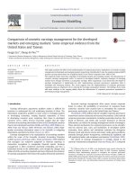
Figure 1.1 The ductile fracture under forming process of plastic deformation [1, 2] .....1
Figure 1.2 Exact prediction of ductile fracture by numerical simulation [2, 4] ..............2
Figure 2.1 Ductile fracture mechanism of metallic material: a) specimen, b) the process
of void nucleation, growth and coalescence during plastic strain evolution [32] ...........7
Figure 2.2 Micro-void nucleation inside AA6061 aluminum alloy specimens: (a)
interface deboning and (b) particle cracking [34]. .......................................................... 8
Figure 2.3 Second phase and non-metallic particles in alloy steel [40] .......................... 9
Figure 2.4 Void nucleation in double phase steel: (a) 2D view, (b) 3D view [41] .......10
Figure 2.5 Microscopic graph of AA6061 alloy [53]: (a) microscopic structure in an
unetched condition; (b) void growth in notched specimen under uniaxial tension .......12
Figure 2.6 The void nucleation (red color) by Zirconia inclusions (light blue color): (a)
homogeneous deformation; (b) localized deformation [55] ..........................................13
Figure 2.7 McClintock’s void growth model (a) solid contains the cylindrical voids; (b)
unit cell model [9]..........................................................................................................14
Figure 2.8 Rice and Tracey void growth model [10]. ...................................................15
Figure 2.9 The Gurson void growth model: a) arbitrary voids in cubic solid, b) a
spherical void in spherical solid [18].............................................................................16
Figure 2.10 Circular cylindrical void in the cylindrical solid [18]. ............................... 17
Figure 2.11 N. L. Dung void growth model: a) cylindrical void; b) ellipsoidal void; c)
void distribution in matrix material [60]. ......................................................................18
Figure 2.12 The first void coalescence mode: a) Benzerga [65] and b, c ) Weck [64] .21
Figure 2.13 Second mode of void coalescence a) and b) Benzerga [67] and
c)
Pardoen et al. [68]). .......................................................................................................21
Figure 2.14 Third void coalescence mode a) and b) Weck [64]; c) Benzerga [67] ......21
Figure 3.1 Illustration of rotation of coordinates system about 3-axis.......................... 32
Figure 3.2 Illustration of void shear mechanism [25] ...................................................35
Figure 3.3 The yield surface presentation of the Dung-Hill48 and pure Hill48 models in
normalized principal stress space ..................................................................................39
Figure 4.1 Geometrical illustration of the “cutting-plane” algorithm ........................... 45
Figure 4.2. Presentation of normal distribution function of void nucleation respect to
equivalent plastic strain .................................................................................................49
Figure 4.3 Unit element (a) uniaxial tension and (b) simple shear ............................... 58
Figure 4.4 True stress-strain curve ................................................................................59
viii
g
Figure 4.5 Effect of softening exponent on evolution of damage variable Dcrit
1 . . 60
g
Figure 4.6 Effect of softening exponent on equivalent stress Dcrit
1 . ...................... 60
Figure 4.7 Effect of critical damage parameter on the evolution of damage variable of
unit element under uniaxial tension 3 . ............................................................... 61
Figure 4.8 Effect of critical damage parameter on the equivalent stress of unit element
under uniaxial tension 3 . ....................................................................................61
Figure 4.9 Effect of hardening exponent on VVF evolution .........................................62
Figure 4.10 Effect of hardening exponent on equivalent stress ....................................62
Figure 4.11 Effect of Lankford’s coefficients on VVF evolution versus equivalent
plastic strain ...................................................................................................................64
Figure 4.12 Effect of Lankford’s coefficients on the equivalent stress correspond to
equivalent plastic strain .................................................................................................64
Figure 4.13 Effect of shear coefficient ( k ) on VVF evolution ....................................64
Figure 4.14 Effect of shear coefficient ( k ) on the element equivalent stress ..............65
Figure 4.15 Geometry, mesh and boundary conditions of tensile test .......................... 67
Figure 4.16 Comparison of the crack path. (a) experiment [91], (b) CDM-Hill48 model,
(c) Dung-Hill48 model ..................................................................................................67
Figure 4.17 Force – displacement curves of tensile test................................................68
Figure 4.18 Diagram of the tooling setup in square cup drawing (a) dimensions (unit:
mm) and (b) finite element model .................................................................................69
Figure 4.19 Comparison of fracture path between experiment and numerical
simulations. (a) experiment, (b) CDM-Hill48 model, (c) Dung-Hill48 model .............69
Figure 4.20 Comparison of forming force curve between experiment and the numerical
simulations ..................................................................................................................... 70
Figure 5.1 Illustration of AA6061-T6 sheet used to create the specimens ...................71
Figure 5.2 ASTM-E8 dog-bone specimen.....................................................................72
Figure 5.3 Tensile test setup .......................................................................................... 72
Figure 5.4 Force - displacement curve of dog-bone specimen......................................72
Figure 5.5 (a) Engineering and (b) true stress versus strain curves .............................. 74
Figure 5.6 The best fit hardening curve.........................................................................76
Figure 5.7 Yield locus in 2D principal stress space of AA6061-T6 sheet ....................77
Figure 5.8 Flowchart of optimized process ...................................................................79
Figure 5.9 FEM mesh and boundary condition of dog-bone specimen ........................ 80
Figure 5.10 The best-fit force-displacement curve using CDM model ......................... 81
ix
Figure 5.11 Force – displacement curve using set of optimum material parameters ....82
Figure 6.1 Dimensions and geometries. (a) R6 specimen, (b) R3 specimen, (c) R1.5
specimen and (d) shear specimen ..................................................................................84
Figure 6.2 Mesh and boundary condition. (a) R6 specimen, (b) R3 specimen, (c) R1.5
specimen and (d) shear specimen ..................................................................................85
Figure 6.3 Force- displacement response of tensile tests ..............................................87
Figure 6.4 No damage occurrence when using a) CDM-Hill48 and b) GTN models
without shear damage variable ...................................................................................... 89
Figure 6.5 The contour of state variables at micro-crack initiation when using DungHill48 model: (a) dog-bone specimen, (b) R6 specimen, (c) R3 specimen, (d) R1.5
specimen and (e) shear specimen ..................................................................................90
Figure 6.6 Micro-crack location of R-notched specimen ..............................................91
Figure 6.7 Contour of state variables at moment just before fracture occurrence when
using CDM-Hill48 model: (a) dog-bone specimen and (b) R6-specimen. ...................92
Figure 6.8 Contour of state variables at moment just before fracture occurrence when
using CDM-Hill48 model: (c) R3 specimen, (d) R1.5 specimen and (e) shear specimen
(cont.) ............................................................................................................................. 93
Figure 6.9 The damage evolution corresponds to equivalent plastic strain ..................94
Figure 6.10 The variation of Lode angle parameter in equivalent plastic strain ...........94
Figure 6.11 Predicted fracture path by CDM-Hill48 and Dung-Hill48 models............95
Figure 6.12 Predicted fracture path by CDM-Hill48 and Dung-Hill48 models (cont.) 96
Figure 6.13 Predicted fracture path by CDM-Hill48 and Dung-Hill48 models (cont.) 97
Figure 6.14 The variation of stress triaxiality in equivalent plastic strain using DungHill48 model ..................................................................................................................98
Figure 6.15 Equivalent plastic fracture strain as a function of average stress triaxiality
.......................................................................................................................................99
Figure 6.16 (a) blank and (b) deep drawing setup (unit: mm) ....................................100
Figure 6.17 Finite element mesh and model: (a) W30 specimen, (b) W55 specimen, (c)
W70 specimen, (d) W90 specimen, (e) W120 specimen, (f) W145 specimen, (g) circular
specimen, (h) finite element model .............................................................................102
Figure 6.18 Illustration of the method to determine limit strains. (a) W30 and (b) W120
specimens.....................................................................................................................103
Figure 6.19 The forming limit diagram of AA6061-T6 aluminum alloy....................104
Figure 6.20 The equivalent plastic fracture strain of AA6061-T6 aluminum alloy ....104
x
LIST OF TABLES
Table 4.1 The material parameter for Dung-Hill48 model ...........................................66
Table 4.2 The material parameter for CDM-Hill48 model ...........................................66
Table 5.1 Chemical composition of AA6061-T6 aluminum alloy................................ 71
Table 5.2 The calculation of the Lankford’s coefficients. ............................................75
Table 5.3 The Swift hardening model parameters ........................................................ 76
Table 5.4 The mechanical properties of AA6061-T6 aluminum alloy ......................... 77
Table 5.5 The anisotropic coefficients of Hill48 equivalent stress function. ................77
Table 5.6 Initial guess values and constrains for optimization process ........................ 80
Table 5.7 The best-fit material parameters for CDM model .........................................80
Table 5.8 Initial guess values and constrains for optimization process ........................ 82
Table 5.9. The optimal values for Dung-Hill48 model .................................................83
Table 6.1 The ductility predictions of the R-notched specimen....................................86
Table 6.2 Average Lode angle parameter values .......................................................... 93
Table 6.3 Summary of fracture initiation location prediction .......................................97
xi
LIST OF ACRONYMS
2D
Two dimensions
3D
Three dimensions
ASTM
American society for testing and materials
CDM
Continuum damage mechanics
CONT.
Continued
FEM
Finite element method
FLD
Forming limit diagram
G
Gurson
GT
Gurson – Tvergaard
GTN
Gurson - Tvergaard – Needleman
ISO
International Organization for Standardization
SEM
Scanning electron microscopy
VUMAT
Vectorized user-defined material
VVF
Void volume fraction
xii
NOMENCLATURE
Operations
aij : bij
Double contraction of aij and bij tensors
d
Rate of
det
Determinant of
x
Partial derivative of
f
Function of
with respect to
x
Absolute value of
Tr
Trace of
Notations
A
Instantaneous cross-section area of specimen
A0
Initial cross-section area of specimen
AN , BN
Number of voids appear during deformation
Softening exponent
Cijkl
Elastic stiffness matrix
D
Damage variable
Dg
Damage variable due to void growth
Ds
Damage variable due to void rotation and void shear
g
Dcrit
Critical damage variable
Dki
Damaged accumulation of cylindrical void in i-direction
Di
Damaged accumulation of spherical void in i-direction
d , d
Plastic multipliers
ij
Delta Kronecker
ϛ
Numerical constant
art
Artificial strain
xiii
Notations (cont.)
ij
Strain tensor
i (i = 1, 2)
Principal strain component
shear
Shear strain
N
Average nucleated strain
Ncrit
Critical nucleated strain
eng
Engineering strain
true
True strain
Equivalent plastic strain of matrix material
p
F, G, H, L, M, L
Anisotropic coefficients of the quadratic yield criterion Hill48
FD
Deep drawing force
Fki
Growth factor in i - direction of cylindrical void (k - axis)
Fi
Growth factor in i - direction of spherical void
FT
Tensile force
f
Void volume fraction
f0
Initial void volume fraction
fc
Void volume fraction at void coalescence (microscopic crack)
fg
Void volume fraction due to existing void growth
fF
Void volume fraction at fracture (macroscopic crack)
fN
Nucleated void volume fraction
fu
Ultimate void volume fraction
Yield criterion
Engineering shear strain
h
Height of cylindrical solid
K ij
Coefficients of nonlinear equations
KB
Function depends on particle shape of Beremin model
J i i 1, 2,3
Invariant of deviatoric stress tensor
xiv
Notations (cont.)
L
Instantaneous gauge length of specimen
L0
Initial gauge length of specimen
Lf
Final gage length of specimen
Lm
Mean distance of two neighbor voids
0
i
Initial distance of two neighbor voids in i - direction
i
Instant distance of two neighbor voids in i – direction
n
Hardening exponent of matrix material
nij
Unit normal vector
Stress triaxiality
Average stress triaxiality
q1 , q2 , q3
Corrected coefficients in porous plastic material model
q4 , q5
Geometrical coefficients in Xue model
R 0o , 45o , 90o Lankford’s coefficients
r
Instant void radius
r0 , ra
Initial void radius
rb
Cell solid radius
ri
Void radius in i-direction
rm
mean void radius
sij
Deviatoric stress tensor
sN
Standard deviator
si i 1, 2,3
Deviatoric stress on principal plane
0
Initial yield stress
i i 1,2,3
Principal stress components
i
Remote principal stress components in i-direction
ij
Cauchy stress tensor
e
Equivalent stress
f
Flow stress of matrix material
xv
Notations (cont.)
m
Mean stress
m
Mean remote stress
N
Average nucleated stress
eng
Engineering stress
true
True stress
Argon
crit
Critical stress of Argon model
Beremin
crit
Critical stress of Beremin model
eMises
von Mises equivalent stress
eHill 48
Hill48 equivalent stress
r
Remote radial stress
z
Remote axial tress
imax
Maximum principal stress in i - direction
Rotated angle of coordinated axes
L
Lode angle
L
Normalized Lode angle
W0
Initial width of specimen
Wf
Final width of specimen
T0
Initial thickness of specimen
Tf
Final thickness of specimen
u
Displacement of tensile test
uD
Punch displacement of deep drawn process
Vtotal
Total volume of unit cell solid
Vmatrix
Volume of matrix
Vvoid
Volume of void
xvi
CHAPTER 1
INTRODUCTION
The research motivation
Nowadays, the sheet metals and their alloys have been widely applied in civil,
automotive and aerospace industries thanks to their light weight and excellent strength
characteristics. These sheet metals are usually used to manufacture products which
formed by forming process under plastic deformation. Nevertheless, the phenomenon of
ductile fracture is usually appearing in such metallic forming process. Today, although
high quality design and manufacturing processes can result in robust, strong products,
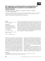
the causation of fail cannot be avoided in some cases. Figure 1.1(a) shows the ductile
fracture of Ti6Al4V alloy which commonly used in aerospace industry under
hydromechanical deep drawing [1] and Figure 1.1(b) displays ductile fracture in single
point incremental forming of pure titanium [2].
(a)
(b)
Figure 1.1 The ductile fracture under forming process of plastic deformation [1, 2]
1
The ductile fracture phenomenon will not be an issue if processes such as damage
causation can be predicted or defective healing [3] is included in the application.
Therefore, the prediction and characterization of micro-crack initiation, fracture
propagation and the final failure of the material is of such importance that it has become
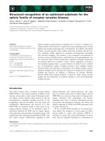
a special field in materials science. For instance, the fractured position and moment can
be exactly predicted by using the reliable damage models as shown in Figure 1.2 [2, 4].
Damage modeling and predicting of metal and nonmetal materials are becoming more
and more important as an object of research in recent years. Until now,
phenomenological continuum damage mechanics combined with finite element method
(FEM) has mostly been used for numerical modeling of a material damage. Two
phenomenological approaches are usually used.
Figure 1.2 Exact prediction of ductile fracture by numerical simulation [2, 4]
The first approach is based on theory of continuum damage mechanics (CDM). In this
method, damage variable is modeled by either scalar variable integrated with an
isotropic yield function for isotropic material [5, 6] or scalar variable integrated with an
anisotropic yield function for anisotropic material [7]. The main advantage of CDM
theory-based model is that there are fewer material parameters compared with the
2
porous ductile material model that will be described in this work. However, one of the
main drawbacks of the CDM theory-based models is their limited validity in the region
of lower and negative stress triaxiality when applied to multiaxial stress states [8]. The
several CDM theory-based typical damage models have been proposed by many
researchers that could be found from literature [9-13]. In this dissertation, a ductile
fracture criterion based on the micro-void growth, N. L. Dung model [12], will be
integrated with CDM theory to investigate the ductile fracture of anisotropic sheet metal.
By observing the fracture surface measurement of high strength structural steel FeE690
using scanning electron microscope (SEM), Schiffman et al. [14] revealed that the N. L.
Dung void growth model can be used to predict void coalescence. Hoa et al. [15]
employed N. L. Dung model for seeking a maximum accumulated damage of the
upsetting problem, the results displayed a coincidence with classical Gurson –
Tvergaard – Needleman (GTN) model. Trung et al. [16] attempted to modify the N. L.
Dung model for only using stress triaxiality and Lode angle space, the modified model
then shown excellently failure predictability of Mg alloy AZ31B [17].
The second approach is based on assumption that the original metallic material
containing the second phase particles and/or the inclusions. Once the matrix material
under plastic deformation, the voids will be borne by separating between hard particles
and matrix material or cracking of soft inclusions. If the deformation of matrix material
is continuous, the voids will be grown and coalesced together that is root of micro-crack
[9, 10]. With increased concentration of micro damage in a material, the spread and
coalescence of which will cause the final macroscopic fracture of the material as critical
conditions are reached. The advantage of these damage models is that they can be used
to describe micromechanical behavior of materials and the physical meaning of the
damage parameters as porosity. Hence these damage models are also known as the
porous ductile material models. A classical model that constituted based on this
approach is that GTN [18-20] model. The original GTN model is proposed based on the
assumptions of isotropic and plastic-rigid material. These assumptions have attracted
attention of researchers, and many kinds of modifications to original GTN model have
been proposed. In order to consider effect of matrix material hardening on void
evolution, the explicitly hardening exponent has supplied by N. L. Dung [21] into the
3
porous ductile yield function. Grange et al. [22] extended the GTN model by taking
plastic anisotropy and viscoplasticity to represent crack propagation of
hydrided
Zircaloy-4 sheets. The original GTN model is also cannot be used to predict the fracture
under pure and simple shear stress states [23, 24]. To improve the prediction accuracy
in shear stress state, Xue [25] and Nahshon and Hutchinson [24] extended the GTN
model through introducing the third invariant of stress tensor to consider the shearing
mechanism. The GTN model has been widely applied to predict ductile fracture of
metallic materials [26-28].
Although there are many damage models can be found from literature and they are also
having accurate predictability of ductile fracture for the various materials. Recently,
advanced high strength steel sheet and aluminum alloy sheet were extensively employed
in automobile industry to satisfy the increasing requirement for high fuel efficiency and
improved safety, the suitable material models are required for more accurately
describing the plastic behavior in sheet metal. Therefore, improving accuracy of ductile
fracture prediction for various sheet metals by using various damage models is still
needed to continue. This research will therefore focus on developing the realistic
damage models including CDM theory – based ductile fracture model and
micromechanics theory - based porous ductile material model. The N. L. Dung models
[12, 21] will be enhanced into account the anisotropy and shear damage in sheet metals.
The research objectives
An investigation of ductile fracture of sheet metallic material and their alloy using the
modified GTN model and modified McClintock model, the N. L. Dung models [12, 21],
will be performed in this dissertation. Therefore, the following specific objectives had
to be achieved in this work:
Firstly, Understanding the mechanism of microscopic ductile fracture of metallic
materials and their alloys.
Secondly, Improving the original damage models for predicting ductile fracture of
anisotropic sheet metals and enhancing them for the case of shear damage prediction.
Thirdly, Developing the user-defined material subroutine (VUMAT) for both porous
ductile material model and CDM theories-based model.
4
Fourthly, Conducting the experiments to determine the mechanical behavior of material
and calibrate the material parameters for the constitutive models.
Fifthly, Applying the damage models to predict the ductile fracture of metallic material
and their alloys.
Research methodology
An approach based on theoretical framework of ductile fracture together with
experimental observation is applied to this dissertation. The ductile damage models of
N. L. Dung [12, 21] are firstly enhanced to anisotropic sheet metal and they are also
modified for shear damage by using the classical CDM and micromechanical ductile
damage theories. After this enhancement the damage models are written in Fortran
program language as the user material subroutines (VUMAT) for the Abaqus/Explicit
FEM package using the numerical algorithms [29, 30]. During this process the code is
frequently verified from various aspects in such a way that it works along with the
existing capability of Abaqus/Explicit software without any errors. Once the VUMAT
subroutines are successfully developed, the damage models would be verified via
predicting ductile fracture of practical application (tensile test, deep drawing…).
The contributions of dissertation
A modified approach to the original damage model of isotropic materials was proposed
by integrating the ductile damage criterion and yield function of porous ductile material
with the quadratic yield criterion Hill48. The aim of this enhancement is to improve the
predicted accuracy of ductile facture in the sheet metals. This approach can be applied
to the more sophisticated yield criteria.
A modification of N. L. Dung models [12, 21] for shear damage case was also performed
in this dissertation. It is noted that the original N. L. Dung models [12, 21] are lack of
the ductile fracture predictability under pure and simple shear loading conditions.
Based on the numerical results, the analytical damage criteria that constructed by
relation between the equivalent ductile fracture strain and the stress triaxialities have
been proposed. These criteria facilitate the implementing become more easier and they
are helping to save computed time by using CDM theory instead of using sophisticated
porous ductile material model.
5
The forming limit diagram (FLD) of sheet aluminum alloy AA6061-T6 was also
predicted by employing the proposed damage models together with the ISO 120042:2008 standard.
In this work, the user material subroutines incorporating CDM plasticity and
micromechanical plasticity into the ABAQUS/Explicit finite element program have
been successfully developed. They can be used as source codes for implementing the
various material models.
Dissertation outline
The present thesis consists of seven chapters, the appendixes and a bibliography of cited
references. Below is a list of contents in each chapter.
Chapter 1 gives motivation, defines objectives and presents an outline of the
dissertation.
An introduction to ductile fracture mechanism of metallic material that occurs due to the
nucleation, growth and coalescence of voids is presented in chapter 2. A reviewing the
existing microscopic void growth - based damage models is also shown in this chapter.
Chapter 3 details the enhancing the closed-form plastic potential function of CDM
model and porous ductile material model for anisotropic material.
The implemented procedures and the numerical algorithms employing for integrating
stress and finding state variables of damage models are represented in chapter 4.
The experiments and an optimization tool applying to this dissertation for identifying
material parameters of hardening and damage models is outlined in chapter 5.
In chapter 6, the finite element calculations for tensile tests and deep drawing process
are performed. The numerical simulations of prediction of ductile fracture in isotropic
and anisotropic metals are also compared to the series of experiment. A ductile fracture
criterion of the aluminum alloy is also proposed based on finite element analysis.
Finally, in chapter 7 conclusions are made based on the results gained in
previous chapters and some discussions are presented for future work.
6
CHAPTER 2
DUCTILE FRACTURE OF METALLIC MATERIAL
Ductile damage mechanism of metallic material
Depending on the loading conditions, damage of metallic material could be caused by
different mechanism; these include cleavage/brittle fracture, ductile fracture, creep and
fatigue [31]. Ductile fracture of metallic material is due to heterogeneous microscopic
structures that decline mechanical properties of the material. The metallic material is
usually containing the resource of microscopic damage such as distributed micro-voids,
which might be process induced during loading, are more tending to crack or failure.
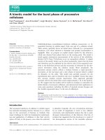
The Figure 2.1 describes the ductile fracture process by micro-void nucleation, growth
and coalescence in metallic material under uniaxial tension [32].
Force (N)
Plastic strain evolution
Void nucleation, growth and coalescence
a)
Displacement (mm)
b)
Figure 2.1 Ductile fracture mechanism of metallic material: a) specimen, b) the
process of void nucleation, growth and coalescence during plastic strain evolution [32]
Impurities of metallic materials and their alloys, such as second phase particles and/or
inclusions, is root of ductile damage. Once metallic material under deformation, the
voids will be appeared by the segregation at interface of the hard particle and matrix or
crack of soft inclusion [33]. It had found that the void nucleation process is strongly
dependent on the particle size and volume. The larger particle size and volume are easier
to cause the void nucleation. The nucleated voids will grow simultaneously if matrix
7