Lab 7.2.4 Selecting the Root Bridge
Bạn đang xem bản rút gọn của tài liệu. Xem và tải ngay bản đầy đủ của tài liệu tại đây (139.03 KB, 6 trang )
1 - 6 CCNA 3: Switching Basics and Intermediate Routing v 3.0 - Lab 7.2.4 Copyright 2003, Cisco Systems, Inc.
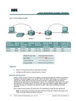
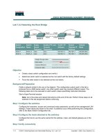
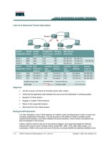
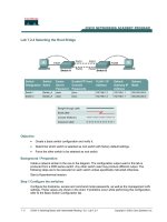
Lab 7.2.4 Selecting the Root Bridge
Objective
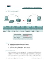
• Create a basic switch configuration and verify it.
• Determine which switch is selected as the root switch with the factory default settings.
• Force the other switch to be selected as the root switch.
Background/Preparation
Cable a network similar to the one in the diagram. The configuration output used in this lab is
produced from a 2950 series switch. Any other switch used may produce different output. The
following steps are to be executed on each switch unless specifically instructed otherwise.
Start a HyperTerminal session.
Note: Go to the erase and reload instructions at the end of this lab. Perform those steps on all
switches in this lab assignment before continuing.
Step 1
Configure the switches
Configure the hostname, access and command mode passwords, as well as the management LAN
settings. These values are shown in the chart. If problems occur while performing this configuration,
refer to the Basic Switch Configuration lab.
Step 2 Configure the hosts attached to the switches
Configure the host to use the same subnet for the address, mask, and default gateway as on the
switch.
Step 3 Verify connectivity
2 - 6 CCNA 3: Switching Basics and Intermediate Routing v 3.0 - Lab 7.2.4 Copyright 2003, Cisco Systems, Inc.
a. To verify that the hosts and switches are correctly configured, ping the switches from the hosts.
b. Were the pings successful?
__________________________________________________
c. If the answer is no, troubleshoot the hosts and switches configurations.
Step 4 Display the show interface VLAN options
a. Type show interface vlan1.
b. List some of the options available:
________________ _______________ _____________
Step 5 Display VLAN interface information
a. On Switch_A, type the command show interface VLAN1 at the privileged EXEC mode
prompt as follows:
Switch_A#show interface vlan 1
b. What is the MAC address of the switch?
_________________________________________
c. On Switch_B type the command show interface VLAN1 at the privileged EXEC mode
prompt as follows:
Switch_B#show interface vlan 1
d. What is the MAC address of the switch?
_________________________________________
e. Which switch should be the root of the spanning tree for VLAN 1?
______________________
Step 6 Display the spanning tree table on each switch
a. At the privileged EXEC mode prompt, type the following on Switch_A:
Type show spanning-tree brief if running version 12.0 of the IOS. If running version 12.1
of the IOS, type show spanning-tree.
Switch_A#show spanning-tree brief
b. On Switch_B type show spanning-tree brief at the privileged EXEC mode prompt as
follows:
Switch_B#show spanning-tree brief
Examine the output and answer the following questions.
c. Which switch is the root switch?
_______________________________________________
d. What is the priority of the root switch?
___________________________________________
e. What is the bridge id of the root switch?
_________________________________________
f. Which ports are forwarding on the root switch?
____________________________________
g. Which ports are blocking on the root switch?
______________________________________
h. What is the priority of the non-root switch?
_______________________________________
i. What is the bridge id of the non-root switch?
______________________________________
j. Which ports are forwarding on the non-root switch?
_________________________________
3 - 6 CCNA 3: Switching Basics and Intermediate Routing v 3.0 - Lab 7.2.4 Copyright 2003, Cisco Systems, Inc.
k. Which ports are blocking on the non-root switch?
__________________________________
l. What is the status of the link light on the blocking port?
______________________________
Step 7 Reassign the root bridge
a. It has been determined that the switch selected as the root bridge, by using default values, is not
the best choice. It is necessary to force the “other” switch to become the root switch.
b. In the example output given the root switch by default, is Switch_A. Switch_B is preferred as the
root switch. Go to the console and enter configuration mode if necessary.
c. Determine the parameters that can be configured for the Spanning-Tree Protocol by issuing the
following:
Switch_B(config)#spanning-tree ?
d. List the options.
_____________
_____________
_____________
_____________
_____________
_____________
_____________
_____________
e. Set the priority of the switch that is not root to 4096.
If version 12.0 is used, enter the following:
Switch_B(config)#spanning-tree priority 1
Switch_B(config)#exit
If version 12.1 is used, enter the following:
Switch_B(config)#spanning-tree vlan 1 priority 4096
Switch_B(config)#exit
Step 8 Display the switch spanning tree table
a. At the privileged EXEC mode prompt, type the following on Switch_A:
Note: Type show spanning-tree brief if running version 12.0 of the IOS. If running
version 12.1 of the IOS, type show spanning-tree.
Switch_A#show spanning-tree brief
b. On Switch_B type show spanning-tree brief at the privileged EXEC mode prompt as
follows:
Switch_B#show spanning-tree brief
Examine the output and answer the following questions.
c. Which switch is the root switch?
_______________________________________________
d. What is the priority of the root switch?
___________________________________________
e. Which ports are forwarding on the root switch?
____________________________________
f. Which ports are blocking on the root switch?
______________________________________
g. What is the priority of the non-root switch?
_______________________________________
4 - 6 CCNA 3: Switching Basics and Intermediate Routing v 3.0 - Lab 7.2.4 Copyright 2003, Cisco Systems, Inc.
h. Which ports are forwarding on the non-root switch?
_________________________________
i. Which ports are blocking on the non-root switch?
__________________________________
j. What is the status of the link light on the blocking port?
______________________________
Step 9 Verify the running configuration file on the root switch
a. On the switch that was changed to be the root bridge, type show running-config at the
privileged EXEC mode prompt.
b. Is there an entry in the running configuration file that specifies the spanning tree priority of this
router?
______________________________________________________________
c. What does that entry say?
___________________________________________________
Note: The output is different depending on if the IOS used is version 12.0 or version 12.1.
Once the steps are complete, log off by typing exit, and turn all the devices off. Then remove and
store the cables and adapter.
5 - 6 CCNA 3: Switching Basics and Intermediate Routing v 3.0 - Lab 7.2.4 Copyright 2003, Cisco Systems, Inc.
Erasing and Reloading the Switch
For the majority of the labs in CCNA 3 and CCNA 4 it is necessary to start with an unconfigured
switch. Use of a switch with an existing configuration may produce unpredictable results. These
instructions allow preparation of the switch prior to performing the lab so previous configuration
options do not interfere. The following is the procedure for clearing out previous configurations and
starting with an unconfigured switch. Instructions are provided for the 2900, 2950, and 1900 Series
switches.
2900 and 2950 Series Switches
1. Enter into the privileged EXEC mode by typing enable.
If prompted for a password, enter class (if that does not work, ask the instructor).
Switch>enable
2. Remove the VLAN database information file.
Switch#delete flash:vlan.dat
Delete filename [vlan.dat]?[Enter]
Delete flash:vlan.dat? [confirm] [Enter]
If there was no VLAN file, this message is displayed.
%Error deleting flash:vlan.dat (No such file or directory)
3. Remove the switch startup configuration file from NVRAM.
Switch#erase startup-config
The responding line prompt will be:
Erasing the nvram filesystem will remove all files! Continue? [confirm]
Press Enter to confirm.
The response should be:
Erase of nvram: complete
4. Check that VLAN information was deleted.
Verify that the VLAN configuration was deleted in Step 2 using the show vlan command. If
previous VLAN configuration information (other than the default management VLAN 1) is still
present it will be necessary to power cycle the switch (hardware restart) instead of issuing the
reload command. To power cycle the switch, remove the power cord from the back of the
switch or unplug it. Then plug it back in.
If the VLAN information was successfully deleted in Step 2, go to Step 5 and restart the switch
using the reload command.
5. Software restart (using the reload command)