GPS - đường dẫn quán tính và hội nhập P4
Bạn đang xem bản rút gọn của tài liệu. Xem và tải ngay bản đầy đủ của tài liệu tại đây (197.34 KB, 23 trang )
4
Receiver and Antenna
Design
4.1 RECEIVER ARCHITECTURE
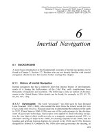
Although there are many variations in GPS receiver design, all receivers must
perform certain basic functions. We will now discuss these functions in detail, each
of which appears as a block in the diagram of the generic receiver shown in Fig. 4.1.
4.1.1 Radio-Frequency Stages (Front End)
The purpose of the receiver front end is to ®lter and amplify the incoming GPS
signal. As was pointed out earlier, the GPS signal power available at the receiver
antenna output terminals is extremely small and can easily be masked by inter-
ference from more powerful signals adjacent to the GPS passband. To make the
signal usable for digital processing at a later stage, RF ampli®cation in the receiver
front end provides as much as 35±55 dB of gain. Usually the front end will also
contain passband ®lters to reduce out-of-band interference without degradation of
the GPS signal waveform. The nominal bandwith of both the L
1
and L
2
GPS signals
is 20 MHz (Æ10 MHz on each side of the carrier), and sharp cutoff bandpass ®lters
are required for out-of-band signal rejection. However, the small ratio of passband
width to carrier frequency makes the design of such ®lters infeasible. Consequently,
®lters with wider skirts are commonly used as a ®rst stage of ®ltering, which also
helps to prevent front-end overloading by strong interference, and the sharp cutoff
®lters are used later after downconversion to intermediate frequencies (IFs).
80
Global Positioning Systems, Inertial Navigation, and Integration,
Mohinder S. Grewal, Lawrence R. Weill, Angus P. Andrews
Copyright # 2001John Wiley & Sons, Inc.
Print ISBN 0-471-35032-X Electronic ISBN 0-471-20071-9
4.1.2Frequency Downconversion and IF Ampli®cation
After ampli®cation in the receiver front end, the GPS signal is converted to a lower
frequency called an intermediate frequency for further ampli®cation and ®ltering.
Downconversion accomplishes several objectives:
1. The total amount of signal ampli®cation needed by the receiver exceeds the
amount that can be performed in the receiver front end at the GPS carrier
frequency. Excessive ampli®cation can result in parasitic feedback oscillation,
which is dif®cult to control. In addition, since sharp cutoff ®lters with a GPS
signal bandwidth are not feasible at the L-band, excessive front-end gain
makes the end-stage ampli®ers vulnerable to overloading by strong nearby
out-of-band signals. By providing additional ampli®cation at an IF different
from the received signal frequency, a large amount of gain can be realized
without the tendency toward oscillation.
2. By converting the signal to a lower frequency, the signal bandwidth is
unaffected, and the increased ratio of bandwidth to center frequency permits
the design of sharp-cutoff bandpass ®lters. These ®lters can be placed ahead of
the IF ampli®ers to prevent saturation by strong out-of-band signals. The
®ltering is often by means of surface acoustic wave (SAW) devices.
BPFBPFBPF
AmpAmp
Amp
Antenna
RF stage First IF stage Second IF stage
First Mixer
Second
Mixer
LO LO
Reference
oscillator
Frequency
synthesizer
Clocks Interrupts
Digitized IF signal
External inputs
(INS, altimeter,
Loran-C,
clock aiding)
Navigation outputs
(position, velocity, time,
fault, detection/isolation)
Navigation
processing
(includes Kalman
filtering)
Code aquisition/tracking
Carrier acquisition/tracking
Message bit synchronization
Navig tion message demodulation
Code/carrier pseudoranging
Delta-range measurements
A/D
converter
a
H/W & S/W Signal Proccessing
Fig. 4.1 Generic GPS receiver.
4.1 RECEIVER ARCHITECTURE
81
3. Conversion of the signal to a lower frequency makes the sampling of the signal
required for digital processing much more feasible.
Downconversion is accomplished by multiplying the GPS signal by a sinusoid
called the local oscillator signal in a device called a mixer. The local oscillator
frequency is either larger or smaller than the GPS carrier frequency by an amount
equal to the IF. In either case the IF signal is the difference between the signal and
local oscillator frequencies. Sum frequency components are also produced, but these
are eliminated by a simple band-pass ®lter following the mixer. An incoming signal
either above or below the local oscillator frequency by an amount equal to the IF will
produce an IF signal, but only one of the two signals is desired. The other signal,
called the image, can be eliminated by bandpass ®ltering of the desired signal prior
to downconversion. However, since the frequency separation of the desired and
image signals is twice the IF, the ®ltering becomes dif®cult if a single down-
conversion to a low IF is attempted. For this reason downconversion is often
accomplished in more than one stage, with a relatively high ®rst IF (30±100 MHz) to
permit image rejection.
Whether it is single stage or multistage, downconversion typically provides a ®nal
IF that is low enough to be digitally sampled at feasible sampling rates without
frequency aliasing. In low-cost receivers typical ®nal IFs range from 4 to 20 MHz
with bandwidths that have been ®ltered down to several MHz. This permits a
relatively low digital sampling rate and at the same time keeps the lower edge of the
signal spectrum well above 0 Hz to prevent spectral foldover. However, for adequate
image rejection either multistage downconversion or a special single-stage image
rejection mixer is required. In more advanced receivers there is a trend toward single
conversion to a signal at a relatively high IF (30±100 MHz), because advances in
technology permit sampling and digitizing even at these high frequencies.
Signal-to-Noise Ratio An important aspect of receiver design is the calculation
of signal quality as measured by the signal-to-noise ratio (SNR) in the receiver IF
bandwith. Typical IF bandwidths range from about 2 MHz in low-cost receivers to
the full GPS signal bandwidth of 20 MHz in high-end units, and the dominant type
of noise is the thermal noise in the ®rst RF ampli®er stage of the receiver front end
(or the antenna preampli®er if it is used). The noise power in this bandwidth is given
by
N kT
e
B 4:1
where k 1:3806 Â 10
À23
J=K, B is the bandwidth in Hz, and T
e
is the effective
noise temperature in degrees Kelvin. The effective noise temperature is a function of
sky noise, antenna noise temperature, line losses, receiver noise temperature, and
ambient temperature. A typical effective noise temperature for a GPS receiver is
513 K, resulting in a noise power of about À138:5 dBW in a 2-MHz bandwidth and
À128:5 dBW in a 20-MHz bandwidth. The SNR is de®ned as the ratio of signal
power to noise power in the IF bandwidth, or the difference of these powers when
82
RECEIVER AND ANTENNA DESIGN
expressed in decibels. Using À154:6 dBW for the received signal power obtained in
Section 3.3, the SNR in a 20-MHz bandwidth is seen to be À154:6 À
À128:5À26:1dB. Although the GPS signal has a 20-MHz bandwidth, about
90% of the C=A-code power lies in a 2-MHz bandwith, so there is only about 0.5 dB
loss in signal power. Consequently the SNR in a 2-MHz bandwidth is
À154:6 À 0:5ÀÀ138:5À16:6 dB. In either case it is evident that the signal
is completely masked by noise. Further processing to elevate the signal above the
noise will be discussed subsequently.
4.1.3 Digitization
In modern GPS receivers digital signal processing is used to track the GPS signal,
make pseudorange and Doppler measurements, and demodulate the 50-bps data
stream. For this purpose the signal is sampled and digitized by an analog-to-digital
converter (ADC). In most receivers the ®nal IF signal is sampled, but in some the
®nal IF signal is converted down to an analog baseband signal prior to sampling. The
sampling rate must be chosen so that there is no spectral aliasing of the sampled
signal; this generally will be several times the ®nal IF bandwidth (2±20 MHz).
Most low-cost receivers use 1-bit quantization of the digitized samples, which not
only is a very low cost method of analog-to-digital conversion, but has the additional
advantage that its performance is insensitive to changes in voltage levels. Thus, the
receiver needs no automatic gain control (AGC). At ®rst glance it would appear that
1-bit quantization would introduce severe signal distortion. However, the noise,
which is Gaussian and typically much larger than the signal at this stage, introduces
a dithering effect that, when statistically averaged, results in an essentially linear
signal component. One-bit quantization does introduce some loss in SNR, typically
about 2 dB, but in low-cost receivers this is an acceptable trade-off. A major
disadvantage of 1-bit quantization is that it exhibits a capture effect in the presence
of strong interfering signals and is therefore quite susceptible to jamming.
Typical high-end receivers use anywhere from 1.5-bit (three-level) to 3-bit (eight-
level) sample quantization. Three-bit quantization essentially eliminates the SNR
degradation found in 1-bit quantization and materially improves performance in the
presence of jamming signals. However, to gain the advantages of multibit quantiza-
tion, the ADC input signal level must exactly match the ADC dynamic range. Thus
the receiver must have AGC to keep the ADC input level constant. Some military
receivers use even more than 3-bit quantization to extend the dynamic range so that
jamming signals are less likely to saturate the ADC.
4.1.4 Baseband Signal Processing
Baseband signal processing refers to a collection of high-speed real-time algorithms
implemented in dedicated hardware and controlled by software that acquire and
track the GPS signal, extract the 50-bps navigation data, and provide measurements
of code and carrier pseudoranges and Doppler.
4.1 RECEIVER ARCHITECTURE
83
Carrier Tracking Tracking of the carrier phase and frequency is accomplished
by using feedback control of a numerically controlled oscillator (NCO) to frequency
shift the signal to precisely zero frequency and phase. Because the shift to zero
frequency results in spectral foldover of the signal sidebands, both in-phase (I ) and a
quadrature (Q) baseband signal components are formed in order to prevent signal
information loss. The I component is generated by multiplying the digitized IF by
the NCO output and the Q component is formed by ®rst introducing a 90
phase lag
in the NCO output before multiplication. Feedback is accomplished by using the
measured baseband phase to control the NCO so that this phase is driven toward
zero. When this occurs, signal power is entirely in the I component, and the Q
component contains only noise. However, both components are necessary both in
order to measure the phase error for feedback and to provide full signal information
during acquisition when phase lock has not yet been achieved. The baseband phase
y
baseband
is de®ned by
y
baseband
atan2I ; Q4:2
where atan2 is the four-quadrant arctangent function. The phase needed for feedback
is recovered from I and Q after despreading of the signal. When phase lock has been
achieved, the output of the NCO will match the incoming IF signal in both frequency
and phase but will generally have much less noise due to low-pass ®ltering used in
the feedback loop. Comparing the NCO phase to a reference derived from the
receiver reference oscillator provides the phase measurements needed for carrier
phase pseudoranging. Additionally, the cycles of the NCO output can be accumu-
lated to provide the raw data for Doppler, delta-range, and integrated Doppler
measurements.
Code Tracking and Signal Spectral Despreading The digitized IF signal,
which has a wide bandwidth due to the C=A- (or P-) code modulation, is completely
obscured by noise. The signal power is raised above the noise power by despreading,
in which the digitized IF signal is multiplied by a receiver-generated replica of the
code precisely time aligned with the code on the received signal. Typically the
individual baseband I and Q signals from the controlled NCO mixer are despread in
parallel, as previously shown in Fig. 3.13. The despreading process removes the
code from the signal, thus concentrating the full signal power into the approximately
50-Hz baseband bandwidth of the data modulation. Subsequent ®ltering (usually in
the form of integration) can now be employed to dramatically raise the SNR to
values permitting observation and measurement of the signal. As an example, recall
that in a GPS receiver a typical SNR in a 2-MHz IF bandwidth is À16:6 dB. After
despreading and 50-Hz low-pass ®ltering the total signal power is still about the
same, but the bandwidth of the noise has been reduced from 2 MHz to about 50 Hz,
which increases the SNR by the ratio 2 Â 10
6
=50, or 46 dB. The resulting SNR is
therefore À16:6 46:0 29:4dB.
84
RECEIVER AND ANTENNA DESIGN
4.2RECEIVER DESIGN CHOICES
4.2.1 Number of Channels and Sequencing Rate
GPS receivers must observe the signal from at least four satellites to obtain three-
dimensional position and velocity estimates. If the user altitude is known, three
satellites will suf®ce. There are several choices as to how the signal observations
from a multiplicity of satellites can be implemented. In early designs, reduction of
hardware cost and complexity required that the number of processing channels be
kept at a minimum, often being smaller than the number of satellites observed. In
this case, each channel must sequentially observe more than one satellite. As a result
of improved lower cost technology, most modern GPS receivers have a suf®cient
number of channels to permit one satellite to be continuously observed on each
channel.
4.2.1.1 Receivers with Channel Time Sharing
Single-Channel Receivers In a single-channel receiver, all processing, such as
acquisition, data demodulation, and code and carrier tracking, is performed by a
single channel in which the signals from all observed satellites are time shared.
Although this reduces hardware complexity, the software required to manage the
time-sharing process can be quite complex, and there are also severe performance
penalties. The process of acquiring satellites can be very slow and requires a
juggling act to track already-acquired satellites while trying to acquire others. The
process is quite tricky when receiving ephemeris data from a satellite, since about
30 s of continuous reception is required. During this time the signals from other
satellites are eclipsed, and resumption of reliable tracking can be dif®cult.
After all satellites have been acquired and their ephemeris data stored, two basic
techniques can be used to track the satellite signals in a single-channel receiver. In
slow-sequencing designs the signal from each satellite is observed for a duration
(dwell time) on the order of 1s. Since a minimum of four satellites must typically be
observed, the signal from each satellite is eclipsed for an appreciable length of time.
For this reason, extra time must be allowed for signal reacquisition at the beginning
of each dwell interval. Continually having to reacquire the signal generally results in
less reliable operation, since the probability of losing a signal is considerably greater
as compared to the case of continuous tracking. This is especially critical in the
presence of dynamics, in which unpredictable user platform motion can take place
during signal eclipse. Generally the positioning and velocity accuracy is also
degraded in the presence of dynamics.
If a single-channel receiver does not have to accurately measure velocity, tracking
can be accomplished with only a frequency-lock loop (FLL) for carrier tracking.
Since a FLL typically has a wider pull-in range and a shorter pull-in time than a
phase-lock loop (PLL), reacquisition of the signal is relatively fast and the
sequencing dwell time can be as small as 0.25 s per satellite. Because loss of
phase lock is not an issue, this type of receiver is also more robust in the presence of
dynamics. On the other hand, if accurate velocity determination is required, a PLL
4.2 RECEIVER DESIGN CHOICES
85
must be used and the extra time required for phase lock during signal reacquisition
pushes the dwell time up to about 1±1.5 s per satellite, with an increased probability
of reacquisition failure due to dynamics.
A single-channel receiver requires relatively complex software for managing the
satellite time-sharing process. A typical design employs only one pseudonoise (PN)
code generator and one PPL in hardware. Typical tasks that the software must
perform during the dwell period for a speci®c satellite are as follows:
1. Select the PN code corresponding to the satellite observed.
2. Compute the current state of the code at the start of the dwell based on the
state at the end of the last dwell, the signal Doppler, and the eclipse time since
the last dwell.
3. Load the code state into the code generator hardware.
4. Compute the initial Doppler frequency of the FLL=PLL reference.
5. Load the Doppler frequency into the FLL=PLL hardware.
6. Initiate the reacquisition process by turning on the code and carrier tracking
loops.
7. Determine when reacquisition (code=frequency=phase lock) has occurred.
8. Measure pseudorange=carrier phase=carrier phase rate during the remainder of
the dwell.
In addition to these tasks, the software must be capable of ignoring measurements
from a satellite if the signal is momentarily lost and must permanently remove the
satellite from the sequencing cycle when its signal becomes unusable, such as when
the satellite elevation angle is below the mask angle. The software must also have the
capability of acquiring new satellites and obtaining their ephemeris data as their
signals become available while at the same time not losing the satellites already
being tracked. A satellite whose ephemeris data is being recorded must have a much
longer dwell time (about 30 s) than the dwell times of other satellites that are only
being tracked, which causes a much longer eclipse time for the latter. The software
must therefore modify the calculations listed above to take this into account.
Because current technology makes the hardware costs of a multichannel receiver
almost as small as that for a single channel, the single-channel approach has been
almost entirely abandoned in modern designs.
Another method of time sharing that can be used in single-channel receivers is
multiplexing, in which the dwell time is much shorter, typically 5±10 ms per satellite.
Because the eclipse time is so short, the satellites do not need to be reacquired at
each dwell. However, a price is paid in that the effective SNR is signi®cantly reduced
in proportion to the number of satellites being tracked. Resistance to jamming is also
degraded by values of 7 dB or more. Additionally, the process of acquiring new
satellites without disruption is made more demanding because the acquisition search
must be broken into numerous short time intervals. Due to the rapidity with which
satellites are sequenced, a common practice with a two-channel receiver is to use a
86
RECEIVER AND ANTENNA DESIGN
full complement of PN code generators that run all the time, so that high-speed
multiplexing of a single code generator can be avoided.
Two-Channel Receivers The use of two channels permits the second channel to
be a ``roving'' channel, in which new satellites can be acquired and ephemeris data
collected while on the ®rst channel satellites can be tracked without slowdown in
position=velocity updates. However, the satellites must still be time shared on the
®rst channel. Thus the software must still perform the functions listed above and in
addition must be capable of inserting=deleting satellites from the sequencing cycle.
As with single-channel designs, either slow sequencing or multiplexing may be
used.
Receivers with Three to Five Channels In either slow-sequencing or multi-
plexed receivers, additional channels will generally permit better accuracy and
jamming immunity as well as more robust performance in the presence of dynamics.
A major breakthrough in receiver performance occurs with ®ve or more channels,
because four satellites can be simultaneously tracked without the need for time
sharing. The ®fth channel can be used to acquire a new satellite and collect its
ephemeris data before using it to replace one of the satellites being tracked on the
other four channels.
Multichannel All-in-ViewReceivers The universal trend in receiver design is to
use enough channels to receive all satellites that are visible. In most cases eight or
fewer useful satellites are visible at any given time; for this reason modern receivers
typically have no more than 10±12 channels, with perhaps several channels being
used for acquisition of new satellites and the remainder for tracking. Position=velo-
city accuracy is materially improved because satellites do not have to be continually
reacquired as is the case with slow sequencing, there is no reduction in effective
SNR found in multiplexing designs, and the use of more than the minimum number
of satellites results in an overdetermined solution. In addition, software design is
much simpler because each channel has its own tracking hardware that tracks only
one satellite and does not have to be time shared.
4.2.2 L
2
Capability
GPS receivers that can utilize the L
2
frequency (1227.60 MHz) gain several
advantages over L
1
-only receivers. Currently the L
2
carrier is modulated only with
a military-encrypted P-code, called the Y-code, and the 50-bps data stream. Because
of the encryption, civilians are denied the use of the P-code. However, it is still
possible to recover the L
2
carrier, which can provide signi®cant performance gains in
certain applications.
Dual-Frequency Ionospheric Correction Because the pseudorange error
caused by the ionosphere is inversely proportional to the square of frequency, it
4.2 RECEIVER DESIGN CHOICES
87
can be calculated in military receivers by comparing the P-code pseudorange
measurements obtained on the L
1
and L
2
frequencies. After subtraction of the
calculated error from the pseudorange measurements, the residual error due to the
ionosphere is typically no more than a few meters as compared to an uncorrected
error of 5±30 m. Although civilians do not have access to the P-code, in differential
positioning applications the L
2
carrier phase can be extracted without decryption,
and the ionospheric error can then be estimated by comparing the L
1
and L
2
phase
measurements.
Improved Carrier Phase Ambiguity Resolution in High-Accuracy Differ-
ential Positioning High-precision receivers, such as those used in surveying,
use carrier phase measurements to obtain very precise pseudoranges. However, the
periodic nature of the carrier makes the measurements highly ambiguous. Therefore,
solution of the positioning equations yields a grid of possible positions separated by
distances on the order of one to four carrier wavelengths, depending on geometry.
Removal of the ambiguity is accomplished by using additional information in the
form of code pseudorange measurements, changes in satellite geometry, or the use of
more satellites than is necessary. In general, ambiguity resolution becomes less
dif®cult as the frequency of the carrier decreases. By using both the L
1
and L
2
carriers, a virtual carrier frequency of L
1
À L
2
1575:42 À 1227:60 347:82 MHz
can be obtained, which has a wavelength of about 86 cm as compared to the 19 cm
wavelength of the L
1
carrier. Ambiguity resolution can therefore be made faster and
more reliable by using the difference frequency.
4.2.3 Code Selections: C=A, P, or Codeless
All GPS receivers are designed to use the C=A-code, since it is the only code
accessible to civilians and is used by the military for initial signal acquisition. Most
military receivers also have P-code capability to take advantage of the improved
performance it offers. On the other hand, commercial receivers seldom have P-code
capability because the government does not make the needed decryption equipment
available to the civil sector. Some receivers, notably those used for precision
differential positioning application, also incorporate a codeless mode that permits
recovery of the L
2
carrier without knowledge of the code waveform.
The C=A-Code The C=A-code, with its 1.023-MHz chipping rate and 1-ms
period, has a bandwidth that permits a reasonably small pseudorange error due to
thermal noise. The code is easily generated by a few relatively small shift registers.
Because the C=A-code has only 1023 chips per period, it is relatively easy to
acquire. In military receivers direct acquisition of the P-code would be extremely
dif®cult and time consuming. For this reason these receivers ®rst acquire the C=A-
code on the L
1
frequency, allowing the 50-bps data stream to be recovered. The data
contains a hand-over word that tells the military receiver a range in which to search
for the P-code.
88
RECEIVER AND ANTENNA DESIGN