Catalogue VALVE
Bạn đang xem bản rút gọn của tài liệu. Xem và tải ngay bản đầy đủ của tài liệu tại đây (15.4 MB, 403 trang )
PARKER HANNIFIN GMBH & CO.KG
HERL REFRIGERATING SPECIALTIES
WANKELSTRASSE 40 D-50996 KÖLN
TEL.(+49) 2236-3900-0
FAX (+49) 2236-3900-39
www.herl.de e-mail:
01/2006
01.00.00
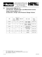
01 Kleinventile DN6 bis 12
als Service-, Entleerungs- und Manometerventile
Small Valves DN6 to 12
as Service-, Purge- and Pressure Gauge Valves
DN
Eck/
Angle
Durch-
gang/
Globe
Material
1
Typ / type
Seite /
page
6-12
X X ST / VA
T34 T34VA
T37 T37VA
01.01.01
6-12
X X ST / VA
T34.S T34VA.S
T37.S T34VA.S
01.01.02
6/15
X VA
T34VA.S9.3
T34VA.S9.3.1
01.01.03
6
X VA
T37VA.S20
01.01.05
6
X ST
T19A
01.01.07
6
X ST
T63.34
01.01.08
1
ST= kaltzäher Stahl / low temperature steel
VA= kaltzäher Edelstahl / low temperature stainless steel
GG= Gußeisen / cast iron
PARKER HANNIFIN GMBH & CO.KG
HERL REFRIGERATING SPECIALTIES
WANKELSTRASSE 40 D-50996 KÖLN
TEL.(+49) 2236-3900-0
FAX (+49) 2236-3900-39
www.herl.de
e-mail:
01/2006
01.01.01
DN
∅A
H H1 H4
∅Hd
S
6 13 120 120 59 60 6
8 17 142 142 75 80 8
10 17 142 142 75 80 8
12 22 142 142 82 80 8
DN
L0
L4
6 130 64
8 166 79
10 166 79
12 182 82
Konform der Richtlinie über Druckgeräte 97/23/EG
Conforming to Pressure Equipment Directive 97/23/EG
HERL T34 T37
T34VA T37VA
Durchgang/Eck- Globe/Angle
Serviceventile Service Valves
für Kältemittel nach for refrigerants acc.to
EN 378-1 (Anhang E) EN 378-1(annex E)
und Kühlsolen and for brines
-60°C / +160 °C
Stahl / steel
TS/°C -60 -40 -10 +50 +100 +160
PN
PS/bar 10.5 28 28 28 28 28
25
PS/bar 10.5 31.5 42 42 33 29.5
40
Edelstahl / stainless steel
TS/°C -60 -50 -10 +50 +100 +160
PN
PS/bar 28 28 28 28 28 28
25
PS/bar 42 42 42 42 33 29.5
40
Ausführung nach: / according to:
EN 12284, EN 378, ISO 5149
Baulänge: / Length:
HERL-Standard
Teil / part Material
steel stainless
steel
1 Gehäuse / body 1.0488/1.0571 1.4301/1.4404
2 Oberteil / bonnet 1.0715 1.4305
3 Überwurfmutter / union nut 1.0715 1.4305
4 Spindel / stem 1.4313 1.4313
5 Kegel / disc 1.0715 1.4301/1.4404
6 Kegeldichtung / disc seal
PTFE-Graphite
1)
7 Sitz / seat 1.0488/1.0571 1.4301/1.4404
8 Packung / packing Graphite
9 Kappe / cap
10 Handrad / handwheel
Al
11 Überwurfmutter / nut 1.0715 1.4305
12 Schweißtülle / tail 1.0401 1.4301/1.4404
14
Rechts-Links-Mutter /
double nut
1.0715 1.4305
¾ Je nach Einsatzbereich ist eine abweichende Ausführung
erforderlich
¾ Depending on the application range different equipment is
required
1) Kegeldichtung alternativ in 1.4313 möglich/
disc seal alternative in 1.4313 possible
Bauhöhe H bezieht sich auf das voll geöffnete Ventil mit Handrad. Ventile mit Kappe oder Handrad. Ventil mit Rückdichtung:
Neuverpacken der Stopfbuchse unter Druck möglich.
Druckprobe mit PS x 1.43 –Medium Wasser, Dichtigkeitsprobe mit PS –Medium Luft.
Total height H refers to the fully opened valve with handwheel. Valves with cap or handwheel. Valve with backseating: Packing
can be repacked under pressure.
Hydraulic pressure test with PS x 1.43 –medium water, tightness test with PS -medium air.
PS = MWB = max. zulässiger Betriebsüberdruck in bar ü / max. allowable working pressure in bar gauge
TS = MWT = Den zulässigen Betriebsüberdrücken (PS) zugeordnete zulässige Betriebstemperatur in °C /
max. allowable working temperature in °C associated with PS
T34/VA
T37/VA
PARKER HANNIFIN GMBH & CO.KG
HERL REFRIGERATING SPECIALTIES
WANKELSTRASSE 40 D-50996 KÖLN
TEL.(+49) 2236-3900-0
FAX (+49) 2236-3900-39
www.herl.de
e-mail:
01/2006
01.01.02
Durchgang / globe type
T34S.../VA
Eck / angle type
T37S.../VA
HERL T34.S T37.S
T34VA.S T37VA.S
Durchgang/Eck- Globe/Angle
Kleinventile Small
Valves
als Service-, Ent- as Service-, Purge-
leerungs-, Manometer- Pressure Gauge
ventile in DN6 bis 12 Valves in DN6 to 12
für Kältemittel nach for refrigerants acc.to
EN 378-1 (Anhang E) EN 378-1(annex E)
und Kühlsolen and for brines
Typbeschreibung siehe auch Seite 01.01.01 /
Type specification see also page 01.01.01
Eintritt/inlet DN 6 Austritt/outlet
Typ
/
type
Gewinde
/
thread
Schweiß-ende
/
butt weld end
Ü-Mutter
/ nut
Tülle
/ tail
Gewinde
/
thread
Ü-Mutter
/
nut
Tülle
/
tail
Blind-
mutter
/
blind nut
Rechts-
Links-
Mutter/
Double-
nut
rght-left
Ermeto-
Schneidring-
Verschraubung
/ Ermeto-type
compression
fitting
S1
13,5 G1/2“ G1/2“ 13,5
S1.0
17,2 G1/2“ G1/2“ 13,5
S1.1
21,3 G1/2“ G1/2“ 13,5
S2
13,5 G1/2“ G1/2“
S2.0
17,2 G1/2“ G1/2“
S2.1
21,3 G1/2“ G1/2“
S3
13,5 G1/2“ 10
S3.0
17,2 G1/2“ 10
S3.1
21,3 G1/2“ 10
S3.3
G1/2” G1/2” 13,5 G1/2” 10
S4
G1/2” G1/2“ 13,5 G1/2“ G1/2”
S6
13,5 G1/2“L G1/2” L/R
S6.0
17,2 G1/2“L G1/2” L/R
S6.1
21,3 G1/2“L G1/2” L/R
S6.3
G1/2“ G1/2“ 13,5 G1/2“L G1/2” L/R
Typ
/
type
Gewinde
/
thread
Adapter
/
Adapter
Gewinde
/
thread
Rechts-
Links-
Mutter
Double-
Nut
right-left
S8
G1/2” G1/2” – G1/4” G1/2“L G1/2” L/R
Diese Ventile können auch in der Ausführung für Schalttafeleinbau geliefert.
These valves can also be supplied for switchboard-installation.
PARKER HANNIFIN GMBH & CO.KG
HERL REFRIGERATING SPECIALTIES
WANKELSTRASSE 40 D-50996 KÖLN
TEL.(+49) 2236-3900-0
FAX (+49) 2236-3900-39
www.herl.de
e-mail:
01/2006
01.01.03
Teil / part Material:
1 Gehäuse / body 1.4301/1.4404
2 Oberteil / bonnet 1.4305
3 Überwurfmutter / cap-nut 1.4305
4 Spindel / stem 1.4313
5 Kegel / disc 1.4301/1.4404
6 Kegeldichtung / disc seal
PTFE-Graphite
1)
7 Sitz / seat 1.4301/1.4404
8 Packung / packing Graphite
9 Kappe / cap
10 Handrad / handwheel
AL
11 Entlüftungsschraube /
ventage screw
A2-70
12 Rechts-Links-Mutter /
Double nut right left
1.4305
13 Blindmutter / blind nut 1.4305
Konform der Richtlinie über Druckgeräte 97/23/EG
Conforming to Pressure Equipment Directive 97/23/EG
HERL T34VA.S9.3
T34VA.S9.3.1
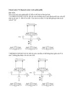
3-Wege-Manometerventil mit Kontrollanschluß
3-way gauge valve with control connection
für Kältemittel nach for refrigerants acc.to
EN 378-1 (Anhang E) EN 378-1(annex E)
und Kühlsolen and for brines
-60°C / +160 °C
TS/°C -60 -50 -10 +50 +100 +160
PN
PS/bar 28 28 28 28 28 28
25
PS/bar 42 42 42 42 33 29.5
40
Ausführung nach: / according to:
EN 12284, EN 378, ISO 5149
Baulänge: / Length:
HERL-Standard
Anschlüsse: / Connections:
Eintritt: / inlet:
Stumpf-Schweißende / butt welding end
Austritt: / outlet:
1. Linksgewinde G1/2-LH mit Spannmuffe als
Manometeranschluß
1. Left hand thread G1/2-LH with double nut
right/ left for gauge
2. Prüf- und Geräteanschlußzapfen mit M20x1,5-
Gewinde und Schutzkappe
2. Test- and process-connection outside thread
M20x1,5, with blind nut
DN A L H H1
∅Hd
∅d
G1 G2 S
6 10 90 130 125 60 6 G1/2 G ½” 6
15 21.3 90 130 125 60 6 G1/2 G ½“ 6
¾ Je nach Einsatzbereich ist eine abweichende Ausführung
erforderlich
¾ Depending on the application range different equipment is
required
1) Kegeldichtung alternativ in 1.4313 möglich/
disc seal alternative in 1.4313 possible
Bauhöhe H bezieht sich auf das voll geöffnete Ventil mit Handrad. Ventile mit Kappe oder Handrad. Ventil mit Rückdichtung:
Neuverpacken der Stopfbuchse unter Druck möglich.
Druckprobe mit PS x 1.43 –Medium Wasser, Dichtigkeitsprobe mit PS Medium Luft.
Total height H refers to the fully opened valve with handwheel. Valves with cap or handwheel. Valve with backseating: Packing
can be repacked under pressure.
Hydraulic pressure test with PS x 1.43 –medium water, tightness test with PS -medium air.
PS = MWB = max. zulässiger Betriebsüberdruck in bar ü / max. allowable working pressure in bar gauge
TS = MWT = Den zulässigen Betriebsüberdrücken (PS) zugeordnete zulässige Betriebstemperatur in °C /
max. allowable working temperature in °C associated with PS
PARKER HANNIFIN GMBH & CO.KG
HERL REFRIGERATING SPECIALTIES
WANKELSTRASSE 40 D-50996 KÖLN
TEL.(+49) 2236-3900-0
FAX (+49) 2236-3900-39
www.herl.de
e-mail:
01/2006
01.01.04
HERL T34VA.S9.3
T34VA.S9.3.1
EINTRITT/INLET
DN6
AUSTRITT/OUTLET
Typ /
type
Gewinde /
thread
Schweiß-
ende /
butt weld
end
Ü-Mutter
/ nut
Tülle
/ tail
Gewinde /
thread
Ü-Mutter
/ nut
Tülle
/ tail
Blindmutter
/ blind nut
Rechts-Links-
Mutter
/ double nut
right/left
S9.3
10 G1/2“L G1/2“L/R
Mit Prüfanschluß M20 und Blindmutter /
With test- and process connection M20 and blind nut
S9.3.1
21,3 G1/2“L G1/2“L/R
Mit Prüfanschluß M20 und Blindmutter /
With test- and process connection M20 and blind nut
PARKER HANNIFIN GMBH & CO.KG
HERL REFRIGERATING SPECIALTIES
WANKELSTRASSE 40 D-50996 KÖLN
TEL.(+49) 2236-3900-0
FAX (+49) 2236-3900-39
www.herl.de
e-mail:
01/2006
01.01.05
Teil / part Material:
1 Gehäuse / body 1.4301/1.4404
2 Oberteil / bonnet 1.4305
3 Überwurfmutter / union nut 1.4305
4 Spindel / stem 1.4313
5 Kegel / disc 1.4301/1.4404
6 Kegeldichtung / disc seal
PTFE-Graphite
1)
7 Sitz / seat 1.4301/1.4404
8 Packung / packing Graphite
9 Kappe / cap
10 Handrad / handwheel
AL
11 Blindmutter / blind nut 1.4305
1) Kegeldichtung alternativ in 1.4313 möglich/
disc seal alternative in 1.4313 possible
Konform der Richtlinie über Druckgeräte 97/23/EG
Conforming to Pressure Equipment Directive 97/23/EG
HERL T37VA.S20
Eck- Angle
Absperrventil Shut off valve
als Entleerungsventil purge valve for
für isolierte Rohrleitungen insulated pipes
für Kältemittel nach for refrigerants acc.to
EN 378-1 (Anhang E) EN 378-1(annex E)
und Kühlsolen and for brines
-60°C / +160 °C
TS/°C -60 -50 -10 +50 +100 +160
PN
PS/bar 28 28 28 28 28 28
25
PS/bar 42 42 42 42 33 29.5
40
Ausführung nach: / according to:
EN 12284, EN 378, ISO 5149
Baulänge: / Length:
HERL-Standard
Anschlüsse: / Connections:
Eintritt/inlet : 1. Anschweißende ∅13.5 (=S20)
∅17.2 (=S20.0)
1. butt welding end ∅13.5 (=S20)
∅17.2 (=S20.0)
Austritt / outlet : Außengewinde G 1/2“ mit Blindmutter/
male thread G 1/2“ with blind nut
DN L H H1 H2
∅C ∅D
E
∅Hd
S
6
42
115
120
90
8.2
16.1
13.5
21.3
G1/2“
60
6
¾ Je nach Einsatzbereich ist eine abweichende Ausführung
erforderlich
¾ Depending on the application range different equipment is
required
Bauhöhe H bezieht sich auf das voll geöffnete Ventil mit Handrad. Ventile mit Kappe oder Handrad. Ventil mit Rückdichtung:
Neuverpacken der Stopfbuchse unter Druck möglich.
Druckprobe mit PS x 1.43 –Medium Wasser, Dichtigkeitsprobe mit PS -Medium Luft.
Total height H refers to the fully opened valve with handwheel. Valves with cap or handwheel. Valve with backseating: Packing
can be repacked under pressure.
Hydraulic pressure test with PS x 1.43 –medium water, tightness test with PS -medium air.
PS = MWB = max. zulässiger Betriebsüberdruck in bar ü / max. allowable working pressure in bar gauge
TS = MWT = Den zulässigen Betriebsüberdrücken (PS) zugeordnete zulässige Betriebstemperatur in °C /
max. allowable working temperature in °C associated with PS
PARKER HANNIFIN GMBH & CO.KG
HERL REFRIGERATING SPECIALTIES
WANKELSTRASSE 40 D-50996 KÖLN
TEL.(+49) 2236-3900-0
FAX (+49) 2236-3900-39
www.herl.de
e-mail:
01/2006
01.01.06
HERL T37VA.S20
EINTRITT/INLET
DN6
AUSTRITT/OUTLET
Typ /
type
Gewinde /
thread
Schweiß-
ende /
butt weld
end
Ü-Mutter
/ nut
Tülle
/ tail
Gewinde /
thread
Ü-Mutter
/ nut
Tülle/tail
Ermeto
Blindmutter
/ blind nut
Rechts-Links-
Mutter
/ double nut
right/left
S20.1
13,5 G1/2“ G1/2”
G1/2“ G1/2”
S20.1.1
21,3 G1/2” G1/2”
S20.2
13.5 G1/2“ G1/2“
G1/2” G1/2“
S20.2.1
21.3 G1/2” G1/2“
S20.3
13.5 G1/2” 10L
G1/2” 10L
S20.3.1
21.3 G1/2” 10L
S20.6
13.5 G1/2” G1/2“
G1/2” G1/2“
S20.6.1
“ 21.3 G1/2” G1/2“
PARKER HANNIFIN GMBH & CO.KG
HERL REFRIGERATING SPECIALTIES
WANKELSTRASSE 40 D-50996 KÖLN
TEL.(+49) 2236-3900-0
FAX (+49) 2236-3900-39
www.herl.de
e-mail:
01/2006
01.01.07
Teil / part Material:
1 Gehäuse / body
2 Oberteil / bonnet
1.0488/1.0571
3 Schrauben / bolts A2.70
4 Spindel / stem 1.4313
5 Kegel / disc
DN6: 1.4313
DN12: 1.0715
6 Kegeldichtung /
disc seal
DN6: 1.4313
DN12: Hartblei/lead tin
1)
7 Sitz / seat 1.0488/1.0571
8 Packung / packing Graphite
9
Handrad/handwheel
10 Kappe / cap
Al
11 Doppelmutter/
double nut
12 Überwurfmutter /
union nut
1.0715
13 Tülle / tail 1.0401
HERL T19A
Serviceventile Service Valves
3-Wege-Ventil
3-Way-Valve
für Kältemittel nach for refrigerants acc.to
EN 378-1 (Anhang E) EN 378-1(annex E)
und Kühlsolen and for brines
-60°C / +160 °C
TS/°C -60 -40 -10 +50 +100 +160
PN
PS/bar 10 19 25 25 25 25
25
PS/bar 10 30 40 40 31.4 28
40
Ausführung nach: / according to:
EN 12284, ISO 5149
Baulänge: / Length:
HERL-Standard
Anschlüsse: / Connections:
Eintritt / Inlet: 1. Anschweißtülle / Tail
Austritt / Outlet: 1. Doppelmutter rechts - links /
double nut right - left
2. Anschweißtülle / tail
(nur DN6 / DN6 only)
DN L H H1 B C
∅Hd
6 106 108 117 G1/2“ 13 80
DN D G S
6 50 G3/8“LH 8
¾ Je nach Einsatzbereich ist eine abweichende Ausführung
erforderlich
¾ Depending on the application range different equipment is
required
1) Kegeldichtung alternativ mit PTFE möglich/
disc seal alternative with PTFE possible
Konform der Richtlinie über Druckgeräte 97/23/EG
Conforming to Pressure Equipment Directive 97/23/EG
Bauhöhe H bezieht sich auf das voll geöffnete Ventil mit Handrad. Ventile mit Kappe oder Handrad. Druckprobe mit PS x 1.43
–Medium Wasser, Dichtigkeitsprobe mit PS -Medium Luft.
Total height H refers to the fully opened valve with handwheel. Valves with cap or handwheel.
Hydraulic pressure test with PS x 1.43 –medium water, tightness test with PS -medium air.
.
PS = MWB = max. zulässiger Betriebsüberdruck in bar ü / max. allowable working pressure in bar gauge
TS = MWT = Den zulässigen Betriebsüberdrücken (PS) zugeordnete zulässige Betriebstemperatur in °C /
max. allowable working temperature in °C associated with PS
PARKER HANNIFIN GMBH & CO.KG
HERL REFRIGERATING SPECIALTIES
WANKELSTRASSE 40 D-50996 KÖLN
TEL.(+49) 2236-3900-0
FAX (+49) 2236-3900-39
www.herl.de
e-mail:
01/2006
01.01.08
Teil / Part Material
1 Gehäuse / body C22.8
2 Spindel / Stem 1.4305
3 Rückdichtung / back seat 1.4305
4 O-Ring Halter / O-ring retainer 1.4305
5 O-Ringe / O-rings Neoprene
6 Kappe / Cap 1.0715
10 Dichtung / gasket Al
11 Rechts-Links-Mutter /
right-left hand nut
1.0715
T63.34
Eck- Angle
Manometerventil Gauge Valve
für Kältemittel nach for refrigerants acc. to
EN 378-1 (Anhang E) EN 378-1(annex E)
und Kühlsolen and for brines
-40°C / +120 °C
Stahl / steel
TS/°C -40 -10 +50 +100 +120
PS
PS/bar 39 52 52 46 45
52
Ausführung nach: / according to:
EN 12284, (DIN 3158), EN 378, ISO 5149
Baulänge: / Length: Herl-Standard
Anschlüsse: / Connections:
Eintritt: ¼“ MPT Außengewinde
Austritt: G1/2”L Außengewinde
mit Rechts/Links-Mutter G1/2“
Inlet: ¼” MPT tapered male
Outlet: G1/2”L parallel thread male
together with double nut G1/2”
Marking: PS-52
DN L1 L2 H G1 G2
6 30 30 90 1/4“ MPT G1/2“L
c/w right-
left-hand
nut G1/2“
¾ Je nach Einsatzbereich ist eine abweichende
Ausführung erforderlich
¾ Depending on the application range different
equipment is required
_________________________________________________________________________________________________
Spindel ist zuverlässig gegen unbeabsichtigtes Herausschrauben gesichert.
Ventil mit Rückdichtung: Neuverpacken der Stopfbuchse unter Druck möglich.
Druckprobe mit PS x 1.43 Wasser, Dichtigkeitsprobe mit PS x 1.1 Luft.
Stem is reliable protected against unintenional unscrewing from the body.
Valve with backseating: Packing can be repacked under pressure.
Hydraulic pressure test with PS x 1.43 water, tightness test with PS x 1.1 air.
PS = MWB = max. zulässiger Betriebsüberdruck in bar ü / max. allowable working pressure in bar gauge
TS = MWT = Den zulässigen Betriebsüberdrücken (PS) zugeordnete zulässige Betriebstemperatur in °C /
max. allowable working temperature in °C associated with PS
PARKER HANNIFIN GMBH & CO.KG
HERL REFRIGERATING SPECIALTIES
WANKELSTRASSE 40 D-50996 KÖLN
TEL.(+49) 2236-3900-0
FAX (+49) 2236-3900-39
www.herl.de
e-mail:
01/2006
02.00.01
02 Handbetätigte
2
Absperrventile /
Hand Operated
2
Shut Off Valves
02.01 DIN-ISO / ASME-ANSI Schweißfasung - Butt Weld End
DN
Eck/
Angle
Durchgang
Globe
Material
1
Typ / type
Seite / page
6-32
X X ST/VA
T5 T6 T5VA T6VA 02.01.01
15-400
X ST
T5F T5F.L 02.01.02
15-400
X ST
T6F T6F.L 02.01.03
15-200
X VA
T5VA.F T5VA.F.L 02.01.04
15-200
X VA
T6VA.F T6VA.F.L 02.01.05
15-150
X ST/VA
T42 T42VA 02.01.06
15-150
X ST/VA
T42.L T42VA.L 02.01.07
02.02 Socket (SW) / NPT Anschluß - Connection
DN
Eck/
Angle
Durchgang
Globe
Material
1
Typ / type
Seite / page
½“-1 ¼“
X ST
T51 T51.SW/FPT
T52.FPT/SW T52
02.02.01
½“-1 ¼“
X ST
T61 T61.SW/FPT
T62.FPT/SW T62
02.02.02
½“-2“
X ST
T51F T52F
T51F.L T52F.L
02.02.03
½“-2“
X ST
T61F T62F
T61F.L T62F.L
02.02.04
02.03 DIN-ISO / ANSI Flanschende – Flange End
DN
Eck/
Angle
Durchgang
Globe
Material
1
Typ / type
Seite / page
15-350 X ST T2V T2V.L 02.03.03
15-200 X ST T11V T11V.L 02.03.04
½“-12“ X ST T4V T4V.L 02.03.07
15-150 X ST/VA T43 T43VA 02.03.08
15-150 X ST/VA T43.L T43VA.L 02.03.09
50-350 X ST/VA T53 T53VA 02.03.10
02.T Technical Information
02.T.00
2
angetriebene Ventile siehe Kapitel 15 / actuated valves see chapter 15
1
ST= kaltzäher Stahl / low temperature steel
VA= kaltzäher Edelstahl / low temperature stainless steel
GG= Gußeisen / cast iron
PARKER HANNIFIN GMBH & CO.KG
HERL REFRIGERATING SPECIALTIES
WANKELSTRASSE 40 D-50996 KÖLN
TEL.(+49) 2236-3900-0
FAX (+49) 2236-3900-39
www.herl.de
e-mail:
01/2006
02.01.00
02.01 DIN-ISO / ASME-ANSI Schweißfasung - Butt Weld End
DN
Eck/
Angle
Durchgang
Globe
Material
1
Typ / type
Seite / page
6-32
X X ST/VA
T5 T6 T5VA T6VA 02.01.01
15-400
X ST
T5F T5F.L 02.01.02
15-400
X ST
T6F T6F.L 02.01.03
15-200
X VA
T5VA.F T5VA.F.L 02.01.04
15-200
X VA
T6VA.F T6VA.F.L 02.01.05
15-150
X ST/VA
T42 T42VA 02.01.06
15-150
X ST/VA
T42.L T42VA.L 02.01.07
1
ST= kaltzäher Stahl / low temperature steel
VA= kaltzäher Edelstahl / low temperature stainless steel
GG= Gußeisen / cast iron
PARKER HANNIFIN GMBH & CO.KG
HERL REFRIGERATING SPECIALTIES
WANKELSTRASSE 40 D-50996 KÖLN
TEL.(+49) 2236-3900-0
FAX (+49) 2236-3900-39
www.herl.de
e-mail:
01/2006
02.01.01
Teil / Part Material
ST
DN6-32
VA
DN6-12
1 Gehäuse / body 1.0488/1.0571 1.4301/1.4404
2 Oberteil / bonnet
3 Ü-mutter/ Cap-nut
1.0715 1.4305
4 Spindel / stem 1.4313
5 Kegel / disc 1.0715 1.4305
6 Kegeldichtung /
disc seal
PTFE-Graphite
7 Sitz / seat 1.0488/1.0571 1.4301/1.4404
8 Packung / packing Graphite
9 Kappe / cap Al
10 Handrad / handwheel Al
Konform der Richtlinie über Druckgeräte 97/23/EG
Conforming to Pressure Equipment Directive 97/23/EG
HERL T5 T6
T5VA T6VA
Durchgang/Eck- Globe/Angle
Absperrventil Shut Off Valve
für Kältemittel nach for refrigerants acc.to
EN 378-1 (Anhang E) EN 378-1(annex E)
und Kühlsolen and for brines
-60°C / +160 °C
Stahl / steel (ST)
DN6-32
TS/°C -60 -40 -10 +50 +100 +160
PN
PS/bar 10.5 28 28 28 28 28
25
PS/bar 10.5 31.5 42 42 33 29.5
40
Edelstahl / stainless steel (VA)
DN6-12
TS/°C -60 -50 -10 +50 +100 +160
PN
PS/bar 28 28 28 28 28 28
25
PS/bar 42 42 42 42 33 29.5
40
Ausführung nach: / according to:
EN 12284, EN 378, ISO 5149
Baulänge: / Length:
HERL-Standard
Anschlüsse: / Connections:
Anschweißenden nach DIN EN 12627
Butt welding ends acc. to DIN EN 12627
T5
DN L H H1 H2
∅Hd
S I
6 70 120 120 20 60 6 50
8 90 142 142 24 80 8 60
10 90 142 142 24 80 8 60
12 100 140 140 29 80 8 60
15 110 140 150 28 80 8 55
20 110 143 153 36 80 8 55
25 130 205 215 49 100 11 90
32 140 208 218 57 100 11 90
T6
DN L1 L2 H H1
∅Hd
S I
6 30 33 119 119 60 6 50
8 37 41 139 139 80 8 60
10 37 41 139 139 80 8 60
12 40 41 139 139 80 8 60
15 40 40 130 140 80 8 55
20 40 40 131 141 80 8 55
25 55 55 187 197 100 11 90
32 63 63 190 200 100 11 90
¾ Je nach Einsatzbereich ist eine abweichende Ausführung
erforderlich
¾ Depending on the application range different equipment is
required
Bauhöhe H bezieht sich auf das voll geöffnete Ventil mit Handrad. Ventile mit Kappe oder Handrad. Ventil mit Rückdichtung:
Neuverpacken der Stopfbuchse unter Druck möglich.
Druckprobe mit PS x 1.43 –Medium Wasser, Dichtigkeitsprobe mit PS -Medium Luft.
Total height H refers to the fully opened valve with handwheel. Valves with cap or handwheel. Valve with backseating: Packing
can be repacked under pressure.
Hydraulic pressure test with PS x 1.43 -medium water, tightness test with PS -medium air
PS = MWB = max. zulässiger Betriebsüberdruck in bar ü / max. allowable working pressure in bar gauge
TS = MWT = Den zulässigen Betriebsüberdrücken (PS) zugeordnete zulässige Betriebstemperatur in °C /
max. allowable working temperature in °C associated with PS
PARKER HANNIFIN GMBH & CO.KG
HERL REFRIGERATING SPECIALTIES
WANKELSTRASSE 40 D-50996 KÖLN
TEL.(+49) 2236-3900-0
FAX (+49) 2236-3900-39
www.herl.de
e-mail:
01/2006
02.01.02
Teil / part Material
1 Gehäuse / body DN15-50
1.0488/1.0571
DN65-400
1.1138.05/1.6220
2 Oberteil / bonnet 1.0488/1.0571
3 Schrauben / bolts A2.70
4 Spindel / stem 1.4313
5 Kegel / disc
DN15-32
1.0715/1.0571
DN40-400
1.0488/1.0571
6 Kegeldichtung /
disc seal
DN15-32
PTFE-Kohle
DN40-400
1)
Hartblei /
Lead tin
7 Sitz / seat
DN15-50
1.0488/1.0571
DN65-400
1.1138.05/1.6220
8 Packung / packing Graphite
9 Kappe / cap Al
10 Handrad / handwheel Al
¾ Je nach Einsatzbereich ist eine abweichende Ausführung
erforderlich
¾ Depending on the application range different equipment is
required
1) DN40-400 Kegeldichtung alternativ mit PTFE-Kohle möglich/
DN40-400 disc seal alternative with PTFE-Graphite possible
Konform der Richtlinie über Druckgeräte 97/23/EG
Conforming to Pressure Equipment Directive 97/23/EG
HERL T5F T5F.L
Durchgang- Globe
Absperrventil Shut Off Valve
für Kältemittel nach for refrigerants acc.to
EN 378-1 (Anhang E) EN 378-1(annex E)
und Kühlsolen and for brines
-60°C / +160 °C
DN15-32
TS/°C -60 -40 -10 +50 +100 +160
PN
PS/bar 10.5 28 28 28 28 28
25
PS/bar 10.5 31.5 42 42 33 29.5
40
DN40-200
TS/°C -60 -50 -10 +50 +100 +160
PN
PS/bar 28 28 28 28 28 27
25
PS/bar 31.5 42 42 42 28 27
40
DN250-400
TS/°C -60 -50 -10 +50 +100 +160
PN
PS/bar 18 25 25 25 16.6 15.6
25
Ausführung nach: / according to:
DIN EN 12284, EN 378, ISO 5149
Baulänge: / Length:
DN15-32 HERL-Standard / DN 40-400 DIN EN 12982
Anschlüsse: / Connections:
Anschweißenden nach DIN EN 12627 oder
ASME-ANSI B16.25 Schedule 40,80 /
Butt welding ends acc. to DIN EN 12627 or
ASME-ANSI B16.25 Schedule 40,80
DN L H H1
∅Hd
S i ++
15 110 165 175 80 8 52 25
20 110 168 178 80 8 48 25
25 130 206 216 100 11 70 46
32 140 208 218 100 11 70 46
40 200 210 220 140 11 60 60
50 230 215 225 140 11 58 60
65 290 325 340 250 17 100 107
80 310 341 356 250 17 90 107
100 350 369 384 250 17 130 107
125 400 406 421 320 17 140 65
150 480 521 536 400 24 150 112
200 600 556 571 400 24 160 134
250 730 765 780 500 27 250 ---
300 850 785 800 500 27 250 ---
350 980 1090 1105 500 27 460 ---
400
1100 1110 1125 500 27 455 ---
++ = Aufmaß für verlängerte Ausführung T5F.L bei i, H und H1
++ = additional length for extended bonnet T5F.L;see i, H and H1
Bauhöhe H bezieht sich auf das voll geöffnete Ventil mit Handrad. Ventile mit Kappe oder Handrad. Ventil mit Rückdichtung:
Neuverpacken der Stopfbuchse unter Druck möglich.
Druckprobe mit PS x 1.43 -Medium Wasser, Dichtigkeitsprobe mit PS -Medium Luft.
Total height H refers to the fully opened valve with handwheel. Valves with cap or handwheel. Valve with backseating: Packing
can be repacked under pressure.
Hydraulic pressure test with PS x 1.43 -medium water, tightness test with PS -medium air.
DN250-400: unbedingt Durchflußrichtung beachten (siehe Kapitel 02.T)
DN250-400: flow direction must be considered under any circumstances (see chapter 02.T)
PS = MWB = max. zulässiger Betriebsüberdruck in bar ü / max. allowable working pressure in bar gauge
TS = MWT = Den zulässigen Betriebsüberdrücken (PS) zugeordnete zulässige Betriebstemperatur in °C /
max. allowable working temperature in °C associated with PS
PARKER HANNIFIN GMBH & CO.KG
HERL REFRIGERATING SPECIALTIES
WANKELSTRASSE 40 D-50996 KÖLN
TEL.(+49) 2236-3900-0
FAX (+49) 2236-3900-39
www.herl.de
e-mail:
01/2006
02.01.03
Teil / part Material
1 Gehäuse / body DN15-80
1.0488/1.0571
DN100-400
1.1138.051/1.6220
2 Oberteil / bonnet 1.0488/1.0571
3 Schrauben / bolts A2.70
4 Spindel / stem 1.4313
5 Kegel / disc
DN15-32
1.0715/1.0571
DN40-400
1.0488/1.0571
6 Kegeldichtung / disc seal DN15-32
PTFE-Kohle
DN40-400
1)
Hartblei /
Lead tin
7 Sitz / seat
DN15-80
1.0488/1.0571
DN100-400
1.1138.05/1.6220
8 Packung / packing Graphite
9 Kappe / cap Al
10 Handrad / handwheel Al
¾ Je nach Einsatzbereich ist eine abweichende Ausführung
erforderlich
¾ Depending on the application range different equipment is
required
1) DN40-400 Kegeldichtung alternativ mit PTFE-Kohle möglich/
DN40-400 disc seal alternative with PTFE-Graphite possible
Konform der Richtlinie über Druckgeräte 97/23/EG
Conforming to Pressure Equipment Directive 97/23/EG
HERL T6F T6F.L
Eck- Angle
Absperrventil Shut Off Valve
für Kältemittel nach for refrigerants acc.to
EN 378-1 (Anhang E) EN 378-1(annex E)
und Kühlsolen and for brines
-60°C / +160 °C
DN15-32
TS/°C -60 -40 -10 +50 +100 +160
PN
PS/bar 10.5 28 28 28 28 28
25
PS/bar 10.5 31.5 42 42 33 29.5
40
DN40-200
TS/°C -60 -50 -10 +50 +100 +160
PN
PS/bar 28 28 28 28 28 27
25
PS/bar 31.5 42 42 42 28 27
40
DN250-400
TS/°C -60 -50 -10 +50 +100 +160
PN
PS/bar 18 25 25 25 16.6 15.6
25
Ausführung nach: / according to:
EN 12284, EN 378, ISO 5149
Baulänge: / Length:
DN15-400 HERL-Standard
Anschlüsse: / Connections:
Anschweißenden nach DIN EN 12627 oder
ASME-ANSI B16.25 Schedule 40,80 /
Butt welding ends acc. to DIN EN 12627 or
ASME-ANSI B16.25 Schedule 40,80
DN L H H1
∅Hd
S i ++
15 40 142 152 80 8 37 25
20 45 143 153 80 8 35 25
25 55 189 199 100 11 50 46
32 60 190 200 100 11 45 46
40 70 184 194 140 11 35 60
50 80 185 195 140 11 30 60
65 95 289 304 250 17 65 107
80 100 296 311 250 17 60 107
100 105 311 326 250 17 65 107
125 146 345 360 320 17 80 65
150 163 461 476 400 24 85 112
200 193 481 496 400 24 75 134
250 325 681 696 500 27 175 ---
300 375 688 703 500 27 160 ---
350 425 954 969 500 27 325 ---
400 475 992 1007 500 27 340 ---
++ = Aufmaß für verlängerte Ausführung T6F.L bei i, H und H1
++ = additional length for extended bonnet T6F.L;see i, H and H1
Bauhöhe H bezieht sich auf das voll geöffnete Ventil mit Handrad. Ventile mit Kappe oder Handrad. Ventil mit Rückdichtung:
Neuverpacken der Stopfbuchse unter Druck möglich.
Druckprobe mit PS x 1.43 -Medium Wasser, Dichtigkeitsprobe mit PS -Medium Luft.
Total height H refers to the fully opened valve with handwheel. Valves with cap or handwheel. Valve with backseating:
Packing can be repacked under pressure.
Hydraulic pressure test with PS x 1.43 -medium water, tightness test with PS -medium air.
DN250-400: unbedingt Durchflußrichtung beachten (siehe Kapitel 02.T)
DN250-400: flow direction must be considered under any circumstances (see chapter 02.T)
PS = MWB = max. zulässiger Betriebsüberdruck in bar ü / max. allowable working pressure in bar gauge
TS = MWT = Den zulässigen Betriebsüberdrücken (PS) zugeordnete zulässige Betriebstemperatur in °C /
max. allowable working temperature in °C associated with PS
PARKER HANNIFIN GMBH & CO.KG
HERL REFRIGERATING SPECIALTIES
WANKELSTRASSE 40 D-50996 KÖLN
TEL.(+49) 2236-3900-0
FAX (+49) 2236-3900-39
www.herl.de
e-mail:
01/2006
02.01.04
Teil / part Material
1 Gehäuse / body DN15-50
1.4301/1.4404
DN65-200
1.4408
2 Oberteil / bonnet 1.4301/1.4404
3 Schrauben / bolts A2.70
4 Spindel / stem 1.4313
5 Kegel / disc DN15-32:
1.0715/1.0571
DN40-200
1.0488/1.0571
6 Kegeldichtung /
disc seal
DN15-32
PTFE-Kohle
DN40-200
1)
Hartblei /
Lead tin
7 Sitz / seat DN15-50
1.4301/1.4404
DN65-200
1.4408
8 Packung / packing Graphite
9 Kappe / cap Al
10 Handrad / handwheel Al
¾ Je nach Einsatzbereich ist eine abweichende Ausführung
erforderlich
¾ Depending on the application range different equipment is
required
1) DN40-200 Kegeldichtung alternativ mit PTFE-Kohle möglich/
DN40-200 disc seal alternative with PTFE-Graphite possible
Konform der Richtlinie über Druckgeräte 97/23/EG
Conforming to Pressure Equipment Directive 97/23/EG
HERL T5VA.F T5VA.F.L
Durchgang- Globe
Absperrventil Shut Off Valve
für Kältemittel nach for refrigerants acc.to
EN 378-1 (Anhang E) EN 378-1(annex E)
und Kühlsolen and for brines
-60°C / +160 °C
DN15-32
TS/°C -60 -40 -10 +50 +100 +160
PN
PS/bar 10.5 28 28 28 28 28
25
PS/bar 10.5 31.5 42 42 33 29.5
40
DN40-200
TS/°C -60 -50 -10 +50 +100 +160
PN
PS/bar 28 28 28 28 28 26.3
25
PS/bar 42 42 42 42 30.3 26.3
40
Ausführung nach: / according to:
EN 12284, EN 378, ISO 5149
Baulänge: / Length:
DN15-32 HERL-Standard / DN 40-200 DIN EN 12982
Anschlüsse: / Connections:
Anschweißenden nach DIN EN 12627 oder
ASME-ANSI B16.25 Schedule 40,80 /
Butt welding ends acc. to DIN EN 12627 or
ASME-ANSI B16.25 Schedule 40,80
DN L H H1
∅Hd
S i ++
15 110 165 175 80 8 52 25
20 110 168 178 80 8 48 25
25 130 206 216 100 11 70 46
32 140 208 218 100 11 70 46
40 200 210 220 140 11 60 60
50 230 215 225 140 11 58 60
65 290 325 340 250 17 100 107
80 310 341 356 250 17 90 107
100 350 369 384 250 17 130 107
125 400 406 421 320 17 140 ---
150 480 521 536 400 24 150 ---
200 600 556 571 400 24 160 ---
++ = Aufmaß für verlängerte Ausführung T5VAF.L bei i, H, H1
++ = additional length for extended bonnet T5VAF.L;see i, H, H1
Bauhöhe H bezieht sich auf das voll geöffnete Ventil mit Handrad. Ventile mit Kappe oder Handrad. Ventil mit Rückdichtung:
Neuverpacken der Stopfbuchse unter Druck möglich.
Druckprobe mit PS x 1.43 -Medium Wasser, Dichtigkeitsprobe mit PS -Medium Luft.
Total height H refers to the fully opened valve with handwheel. Valves with cap or handwheel. Valve with backseating:
Packing can be repacked under pressure.
Hydraulic pressure test with PS x 1.43 -medium water, tightness test with PS -medium air.
PS = MWB = max. zulässiger Betriebsüberdruck in bar ü / max. allowable working pressure in bar gauge
TS = MWT = Den zulässigen Betriebsüberdrücken (PS) zugeordnete zulässige Betriebstemperatur in °C /
max. allowable working temperature in °C associated with PS
PARKER HANNIFIN GMBH & CO.KG
HERL REFRIGERATING SPECIALTIES
WANKELSTRASSE 40 D-50996 KÖLN
TEL.(+49) 2236-3900-0
FAX (+49) 2236-3900-39
www.herl.de
e-mail:
01/2006
02.01.05
Teil / part Material
1 Gehäuse / body DN15-80
1.4301/1.4404
DN100-200
1.4408
2 Oberteil / bonnet 1.4301/1.4404
3 Schrauben / bolts A2.70
4 Spindel / stem 1.4313
5 Kegel / disc DN15-32:
1.0715/1.0571
DN40-200:
1.4408/1.0571
6 Kegeldichtung /
disc seal
DN15-32
PTFE-Kohle
1)
DN40-200
Hartblei/Lead tin
7 Sitz / seat DN15-80
1.4301/1.4404
DN100-200
1.4408
8 Packung/packing Graphite
9 Kappe / cap Al
10 Handrad/handwh. Al
¾ Je nach Einsatzbereich ist eine abweichende Ausführung
erforderlich
¾ Depending on the application range different equipment is
required
1) DN40-200 Kegeldichtung alternativ mit PTFE-Kohle
möglich/
DN40-200 disc seal alternative with PTFE-Graphite
possible
Konform der Richtlinie über Druckgeräte 97/23/EG
Conforming to Pressure Equipment Directive 97/23/EG
HERL T6VA.F T6VA.F.L
Eck- Angle
Absperrventil Shut Off Valve
für Kältemittel nach for refrigerants acc.to
EN 378-1 (Anhang E) EN 378-1(annex E)
und Kühlsolen and for brines
-60°C / +160 °C
DN15-32
TS/°C -60 -40 -10 +50 +100 +160
PN
PS/bar 10.5 28 28 28 28 28
25
PS/bar 10.5 31.5 42 42 33 29.5
40
DN40-200
TS/°C -60 -50 -10 +50 +100 +160
PN
PS/bar 28 28 28 28 28 26.3
25
PS/bar 42 42 42 42 30.3 26.3
40
Ausführung nach: / according to:
EN 12284, EN 378, ISO 5149
Baulänge: / Length:
DN15-200 HERL-Standard
Anschlüsse: / Connections:
Anschweißenden nach DIN EN 12627 oder
ASME-ANSI B16.25 Schedule 40,80 /
Butt welding ends acc. to DIN EN 12627 or
ASME-ANSI B16.25 Schedule 40,80
DN L H H1
∅Hd
S i ++
15 40 142 152 80 8 37 25
20 45 143 153 80 8 35 25
25 55 189 199 100 11 50 46
32 60 190 200 100 11 45 46
40 70 184 194 140 11 35 60
50 80 185 195 140 11 30 60
65 95 289 304 250 17 65 107
80 100 296 311 250 17 60 107
100 105 311 326 250 17 65 107
125 146 345 360 320 17 80 --
150 163 461 476 400 24 85 --
200 193 481 496 400 24 75 --
++ = Aufmaß für verlängerte Ausführung T6VA.F.L bei i, H, H1
++ = additional length for extended bonnet T6VA.F.L;see i, H, H1
Bauhöhe H bezieht sich auf das voll geöffnete Ventil mit Handrad. Ventile mit Kappe oder Handrad. Ventil mit Rückdichtung:
Neuverpacken der Stopfbuchse unter Druck möglich.
Druckprobe mit PS x 1.43 -Medium Wasser, Dichtigkeitsprobe mit PS -Medium Luft.
Total height H refers to the fully opened valve with handwheel. Valves with cap or handwheel. Valve with backseating:
Packing can be repacked under pressure.
Hydraulic pressure test with PS x 1.43 -medium water, tightness test with PS -medium air.
PS = MWB = max. zulässiger Betriebsüberdruck in bar ü / max. allowable working pressure in bar gauge
TS = MWT = Den zulässigen Betriebsüberdrücken (PS) zugeordnete zulässige Betriebstemperatur in °C /
max. allowable working temperature in °C associated with PS
PARKER HANNIFIN GMBH & CO.KG
HERL REFRIGERATING SPECIALTIES
WANKELSTRASSE 40 D-50996 KÖLN
TEL.(+49) 2236-3900-0
FAX (+49) 2236-3900-39
www.herl.de
e-mail:
03/2006
02.01.06
Teil / part Material T42 Material T42 VA
1 Gehäuse / body DN15-65
C22.8
DN80-150
GS-C 25
DN15-65
1.4404
DN80-150
1.4408
2 Kugel / ball 1.4021 / 1.4404 1.4404 / 1.4408
3 Schaltwelle /
stem
1.4021 / 1.4404 1.4404 / 1.4408
4 Gehäusedicht. /
body seal
PTFE
5 Dichtschale /
flow seal
PTFE
6 Stopfbuchse /
packing
PTFE, Glasfaser
PTFE, fibreglass
7 Wellendichtung
/ stem seal
PTFE, Glasfaser
PTFE, fibreglass
8 Tellerfeder /
plate spring
1.4310
9 Handhebel /
lever
C15
¾ Je nach Einsatzbereich ist eine abweichende Ausführung
erforderlich
¾ Depending on the application range different equipment is
required
Konform der Richtlinie über Druckgeräte 97/23/EG
Conforming to Pressure Equipment Directive 97/23/EG
HERL T42 T42VA
Absperr- Shut - Off
Kugelventil Ball Valve
für Kältemittel nach for refrigerants acc.to
EN 378-1 (Anhang E) EN 378-1(annex E)
und Kühlsolen and for brines
-60°C / +200 °C
TS/°C -60 -40 -10 +50 +100 +150 +200
PN
PS/bar 10 30 40 40 36 34 31
40
Ausführung nach: / according to:
EN 12284, EN 378, ISO 5149
Baulänge: / Length:
HERL-Standard
Anschlüsse: / Connections:
Anschweißenden nach DIN EN 12627
DN L L1 L2 H1 H2
15 65 20,4 140 40 55
20 72,5 24,5 140 42 57
25 85,4 31,4 180 53 74
32 99,3 41,3 180 58 77
40 110,4 48,4 200 71 89
50 126,3 56,3 200 76 94
65 142,6 71,4 250 86 110
80 169,5 88,9 480 153 161
100 214 108,5 480 168 176
125 277 134,6 480 182 190
150 307 134,6 480 182 190
Kugel mit Entlastungsbohrung. Reduzierter Durchgang. Ventil mit Handhebel. Ventil mit Schaltwellendichtung:
Neuverpacken der Stopfbuchse unter Druck möglich.
Druckprobe mit PS x 1.43 -Medium Wasser, Dichtigkeitsprobe mit PS -Medium Luft.
Ball with bleed hole. Reduced bore. Ball valve with lever. Valve with stem seal:
Packing can be repacked under pressure.
Hydraulic pressure test with PS x 1.43 -medium water, tightness test with PS -medium air.
PS = MWB = max. zulässiger Betriebsüberdruck in bar ü / max. allowable working pressure in bar gauge
TS = MWT = Den zulässigen Betriebsüberdrücken (PS) zugeordnete zulässige Betriebstemperatur in °C /
max. allowable working temperature in °C associated with PS
PARKER HANNIFIN GMBH & CO.KG
HERL REFRIGERATING SPECIALTIES
WANKELSTRASSE 40 D-50996 KÖLN
TEL.(+49) 2236-3900-0
FAX (+49) 2236-3900-39
www.herl.de
e-mail:
03/2006
02.01.07
Teil / part Material T42.L Material T42 VA.L
1 Gehäuse / body DN15-50
C22.8
DN80-150
GS-C 25
DN15-50
1.4404
DN80-150
1.4408
2 Kugel / ball 1.4021 1.4404 / 1.4408
3 Schaltw. / stem 1.4404
4 Gehäusedicht. /
body seal
PTFE
5 Dichtschale /
flow seal
PTFE
6 Stopfbuchse /
packing
PTFE, Glasfaser PTFE, fibreglass
7 Wellendichtung
/ stem seal
PTFE, Glasfaser PTFE, fibreglass
8 Tellerfeder /
plate spring
1.4310
9 Hebel / lever C15
1
0
Verlängerung /
extension
1.4305
¾ Je nach Einsatzbereich ist eine abweichende Ausführung
erforderlich
¾
Depending on the application range different equipment is
required
HERL T42.L T42VA.L
Absperr- Shut - Off
Kugelventil Ball Valve
für Kältemittel nach for refrigerants acc.to
EN 378-1 (Anhang E) EN 378-1(annex E)
und Kühlsolen and for brines
-60°C / +200 °C
TS/°C -60 -40 -10 +50 +100 +150 +200
PN
PS/bar 10 30 40 40 36 34 31
40
Ausführung nach: / according to:
EN 12284, EN 378, ISO 5149
Baulänge: / Length:
HERL-Standard
Anschlüsse: / Connections:
Anschweißenden nach DIN EN 12627
DN L L1 L2 H1 H2
15 65 20,4 140 140 155
20 72,5 24,5 140 142 157
25 85,4 31,4 180 153 174
32 99,3 41,3 180 158 177
40 110,4 48,4 200 171 189
50 126,3 56,3 200 176 194
65 142,6 71,4 250 186 210
80 169,5 88,9 480 253 261
100 214 108,5 480 268 276
125 277 134,6 480 282 290
150 307 134,6 480 282 290
Konform der Richtlinie über Druckgeräte 97/23/EG
Conforming to Pressure Equipment Directive 97/23/EG
Kugel mit Entlastungsbohrung. Reduzierter Durchgang. Ventil mit Handhebel. Ventil mit Schaltwellendichtung:
Neuverpacken der Stopfbuchse unter Druck möglich.
Druckprobe mit PS x 1.43 -Medium Wasser, Dichtigkeitsprobe mit PS -Medium Luft.
Ball with bleed hole. Reduced bore. Ball valve with lever. Valve with stem seal:
Packing can be repacked under pressure.
Hydraulic pressure test with PS x 1.43 -medium water, tightness test with PS -medium air.
PS = MWB = max. zulässiger Betriebsüberdruck in bar ü / max. allowable working pressure in bar gauge
TS = MWT = Den zulässigen Betriebsüberdrücken (PS) zugeordnete zulässige Betriebstemperatur in °C /
max. allowable working temperature in °C associated with PS
PARKER HANNIFIN GMBH & CO.KG
HERL REFRIGERATING SPECIALTIES
WANKELSTRASSE 40 D-50996 KÖLN
TEL.(+49) 2236-3900-0
FAX (+49) 2236-3900-39
www.herl.de
e-mail:
01/2006
02.02.00
02.02 Socket (SW) / NPT Anschluß - Connection
DN
Eck/
Angle
Durchgang
Globe
Material
1
Typ / type
Seite / page
½“-1 ¼“
X ST
T51 T51.SW/FPT
T52.FPT/SW T52
02.02.01
½“-1 ¼“
X ST
T61 T61.SW/FPT
T62.FPT/SW T62
02.02.02
½“-2“
X ST
T51F T51F.SW/FPT
T52F.FPT/SW T52F
T51F.L T52F.L
T51F.L.SW/FPT
T52F.L.FPT/SW
02.02.03
½“-2“
X ST
T61F T61F.SW/FPT
T62F.FPT/SW T62F
T61F.L T62F.L
T61F.L.SW/FPT
T62F.L.FPT/SW
02.02.04
PARKER HANNIFIN GMBH & CO.KG
HERL REFRIGERATING SPECIALTIES
WANKELSTRASSE 40 D-50996 KÖLN
TEL.(+49) 2236-3900-0
FAX (+49) 2236-3900-39
www.herl.de
e-mail:
01/2006
02.02.01
Teil / part Material:
1 Gehäuse / body 1.0488/1.0571
2 Oberteil / bonnet 1.0715
3 Überwurfmutter / Cap-nut
Schrauben / bolts
1.0715
VA
4 Spindel / stem 1.4313
5 Kegel / disc 1.0715
6 Kegeldichtung / disc seal PTFE
7 Sitz / seat 1.0488/1.0571
8 Packung / packing Graphite
9 Kappe / cap Al
10 Handrad / handwheel Al
¾ Je nach Einsatzbereich ist eine abweichende Ausführung
erforderlich
¾ Depending on the application range different equipment is
required
Konform der Richtlinie über Druckgeräte 97/23/EG
Conforming to Pressure Equipment Directive 97/23/EG
HERL T51 T51.SW/FPT
T52 T52.FPT/SW
Durchgang- Globe
Absperrventil Shut Off Valve
für Kältemittel nach for refrigerants acc.to
EN 378-1 (Anhang E) EN 378-1(annex E)
und Kühlsolen and for brines
-60°C / +160 °C
TS/°C -60 -40 -10 +50 +100 +160
PN
PS/bar 10.5 28 28 28 28 28
25
PS/bar 10.5 31.5 42 42 33 29.5
40
Ausführung nach: / according to:
EN 12284, EN 378, ISO 5149
Baulänge: / Length:
HERL-Standard
Anschlüsse: / Connections:
TYP
Eintritt / Inlet Austritt / Outlet
T51
Muffen-Schweißenden
nach ANSI B16.11 /
socket welding ends acc.
to ANSI B16.11
Muffen-Schweißenden
nach ANSI B16.11 /
socket welding ends
acc. to ANSI B16.11
T52
Gewindeanschluß /
Thread FPT acc.to ANSI
B1.20.1
Gewindeanschluß /
Thread FPT acc.to ANSI
B1.20.1
T51.
SW/
FPT
Muffen-Schweißenden
nach ANSI B16.11 /
socket welding ends acc.
to ANSI B16.11
Gewindeanschluß /
Thread FPT acc.to ANSI
B1.20.1
T52.
FPT/
SW
Gewindeanschluß /
Thread FPT acc.to ANSI
B1.20.1
Muffen-Schweißenden
nach ANSI B16.11 /
socket welding ends
acc. to ANSI B16.11
INCH L H H1
∅Hd
S
½ 130 155 165 80 8
¾ 130 158 168 80 8
1 150 208 218 100 11
1 ¼“ 160 211 221 100 11
Bauhöhe H bezieht sich auf das voll geöffnete Ventil mit Handrad. Ventile mit Kappe oder Handrad. Ventil mit Rückdichtung:
Neuverpacken der Stopfbuchse unter Druck möglich.
Druckprobe mit PS x 1.43 -Medium Wasser, Dichtigkeitsprobe mit PS -Medium Luft.
Total height H refers to the fully opened valve with handwheel. Valves with cap or handwheel. Valve with backseating: Packing
can be repacked under pressure.
Hydraulic pressure test with PS x 1.43 -medium water, tightness test with PS -medium air.
PS = MWB = max. zulässiger Betriebsüberdruck in bar ü / max. allowable working pressure in bar gauge
TS = MWT = Den zulässigen Betriebsüberdrücken (PS) zugeordnete zulässige Betriebstemperatur in °C /
max. allowable working temperature in °C associated with PS
PARKER HANNIFIN GMBH & CO.KG
HERL REFRIGERATING SPECIALTIES
WANKELSTRASSE 40 D-50996 KÖLN
TEL.(+49) 2236-3900-0
FAX (+49) 2236-3900-39
www.herl.de
e-mail:
01/2006
02.02.02
Teil / part Material:
1 Gehäuse / body 1.0488/1.0571
2 Oberteil / bonnet 1.0715
3 Überwurfmutter / Cap-nut
Schrauben / bolts
1.0715
VA
4 Spindel / stem 1.4313
5 Kegel / disc 1.0715
6 Kegeldichtung / disc seal PTFE
7 Sitz / seat 1.0488/1.0571
8 Packung / packing Graphite
9 Kappe / cap Al
10 Handrad / handwheel Al
¾ Je nach Einsatzbereich ist eine abweichende Ausführung
erforderlich
¾ Depending on the application range different equipment is
required
Konform der Richtlinie über Druckgeräte 97/23/EG
Conforming to Pressure Equipment Directive 97/23/EG
HERL T61 T61.SW/FPT
T62 T62.FPT/SW
Eck- Angle
Absperrventil Shut Off Valve
für Kältemittel nach for refrigerants acc.to
EN 378-1 (Anhang E) EN 378-1(annex E)
und Kühlsolen and for brines
-60°C / +160 °C
TS/°C -60 -40 -10 +50 +100 +160
PN
PS/bar 10.5 28 28 28 28 28
25
PS/bar 10.5 31.5 42 42 33 29.5
40
Ausführung nach: / according to:
EN 12284, EN 378, ISO 5149
Baulänge: / Length:
HERL-Standard
Anschlüsse: / Connections:
TYP
Eintritt / Inlet Austritt / Outlet
T61
Muffen-Schweißenden
nach ANSI B16.11 /
socket welding ends acc.
to ANSI B16.11
Muffen-Schweißenden
nach ANSI B16.11 /
socket welding ends
acc. to ANSI B16.11
T62
Gewindeanschluß /
Thread FPT acc.to ANSI
B1.20.1
Gewindeanschluß /
Thread FPT acc.to ANSI
B1.20.1
T61.
SW/
FPT
Muffen-Schweißenden
nach ANSI B16.11 /
socket welding ends acc.
to ANSI B16.11
Gewindeanschluß /
Thread FPT acc.to ANSI
B1.20.1
T62.
FPT/
SW
Gewindeanschluß /
Thread FPT acc.to ANSI
B1.20.1
Muffen-Schweißenden
nach ANSI B16.11 /
socket welding ends
acc. to ANSI B16.11
INCH L H H1
∅Hd
S
½ 40 142 152 80 8
¾ 40 143 153 80 8
1 55 189 199 100 11
1 ¼ 60 190 200 100 11
Bauhöhe H bezieht sich auf das voll geöffnete Ventil mit Handrad. Ventile mit Kappe oder Handrad. Ventil mit Rückdichtung:
Neuverpacken der Stopfbuchse unter Druck möglich.
Druckprobe mit PS x 1.43 -Medium Wasser, Dichtigkeitsprobe mit PS -Medium Luft.
Total height H refers to the fully opened valve with handwheel. Valves with cap or handwheel. Valve with backseating: Packing
can be repacked under pressure.
Hydraulic pressure test with PS x 1.43 -medium water, tightness test with PS -medium air.
PS = MWB = max. zulässiger Betriebsüberdruck in bar ü / max. allowable working pressure in bar gauge
TS = MWT = Den zulässigen Betriebsüberdrücken (PS) zugeordnete zulässige Betriebstemperatur in °C /
max. allowable working temperature in °C associated with PS
PARKER HANNIFIN GMBH & CO.KG
HERL REFRIGERATING SPECIALTIES
WANKELSTRASSE 40 D-50996 KÖLN
TEL.(+49) 2236-3900-0
FAX (+49) 2236-3900-39
www.herl.de
e-mail:
01/2006
02.02.03
Teil / part Material:
1 Gehäuse / body
2 Oberteil / bonnet
1.0488/1.0571
3 Schrauben / bolts A2.70
4 Spindel / stem 1.4313
5 Kegel / disc DN 15-32: 1.0715/1.0571
DN40-50: 1.0488/1.0571
6 Kegeldichtung / disc seal 1/2“-11/4“: PTFE
11/2“-2“:
1)
Hartblei / lead tin
7 Sitz / seat 1.0488/1.0571
8 Packung / packing Graphite
9 Kappe / cap Al
10 Handrad / handwheel Al
¾ Je nach Einsatzbereich ist eine abweichende Ausführung
erforderlich
¾ Depending on the application range different equipment is
required
1)
1 1/2“-2“
Kegeldichtung alternativ mit PTFE möglich/
1 1/2“-2“
disc seal alternative with PTFE possible
Konform der Richtlinie über Druckgeräte 97/23/EG
Conforming to Pressure Equipment Directive 97/23/EG
HERL T51F T51F.SW/FPT
T52F T52F.FPT/SW
Durchgang- Globe
Absperrventil Shut Off Valve
für Kältemittel nach for refrigerants acc.to
EN 378-1 (Anhang E) EN 378-1(annex E)
und Kühlsolen and for brines
-60°C / +160 °C
TS/°C -60 -40 -10 +50 +100 +160
PN
PS/bar 10.5 28 28 28 28 28
25
PS/bar 10.5 31.5 42 42 33 29.5
40
Ausführung nach: / according to:
EN 12284, EN 378, ISO 5149
Baulänge: / Length:
HERL-Standard
Anschlüsse: / Connections:
TYP INCH
Eintritt / Inlet Austritt / Outlet
T51F
½“-2“ Muffen-
Schweißenden nach
ANSI B16.11 /
socket welding ends
acc. to ANSI B16.11
Muffen-
Schweißenden nach
ANSI B16.11 /
socket welding ends
acc. to ANSI B16.11
T52F
½“-
1 ¼“
Gewindeanschluß /
Thread FPT acc.to
ANSI B1.20.1
Gewindeanschluß /
Thread FPT acc.to
ANSI B1.20.1
T51F.
SW/
FPT
½“-
1 ¼“
Muffen-
Schweißenden nach
ANSI B16.11 /
socket welding ends
acc. to ANSI B16.11
Gewindeanschluß /
Thread FPT acc.to
ANSI B1.20.1
T52F.
FPT/
SW
½“-
1 ¼“
Gewindeanschluß /
Thread FPT acc.to
ANSI B1.20.1
Muffen-
Schweißenden nach
ANSI B16.11 /
socket welding ends
acc. to ANSI B16.11
INCH L H H1
∅Hd
S i ++
½ 130 190 200 80 8 52 25
¾ 130 193 203 80 8 48 25
1 150 252 262 100 11 70 46
1 ¼ 160 254 264 100 11 70 46
1 ½ 200 270 280 140 11 60 60
2 230 275 285 140 11 58 60
++ = Aufmaß für verlängerte Ausführung T51F.L.. bei i, H, H1
++ = additional length for extended bonnet T51F.L..;see i, H, H1
Bauhöhe H bezieht sich auf das voll geöffnete Ventil mit Handrad. Ventile mit Kappe oder Handrad. Ventil mit Rückdichtung:
Neuverpacken der Stopfbuchse unter Druck möglich.
Druckprobe mit PS x 1.43 -Medium Wasser, Dichtigkeitsprobe mit PS -Medium Luft.
Total height H refers to the fully opened valve with handwheel. Valves with cap or handwheel. Valve with backseating: Packing
can be repacked under pressure.
Hydraulic pressure test with PS x 1.43 -medium water, tightness test with PS -medium air.
PS = MWB = max. zulässiger Betriebsüberdruck in bar ü / max. allowable working pressure in bar gauge
TS = MWT = Den zulässigen Betriebsüberdrücken (PS) zugeordnete zulässige Betriebstemperatur in °C /
max. allowable working temperature in °C associated with PS
PARKER HANNIFIN GMBH & CO.KG
HERL REFRIGERATING SPECIALTIES
WANKELSTRASSE 40 D-50996 KÖLN
TEL.(+49) 2236-3900-0
FAX (+49) 2236-3900-39
www.herl.de
e-mail:
01/2006
02.02.04
Teil / part Material:
1 Gehäuse / body
2 Oberteil / bonnet
1.0488/1.0571
3 Schrauben / bolts A2.70
4 Spindel / stem 1.4313
5 Kegel / disc 1.0715/1.0571
6 Kegeldichtung /
disc seal
1/2“-11/4“: PTFE
11/2“-2“:
1)
Hartblei /
lead tin
7 Sitz / seat 1.0488/1.0571
8 Packung / packing Graphite
9 Kappe / cap Al
10 Handrad / handwheel Al
¾ Je nach Einsatzbereich ist eine abweichende Ausführung
erforderlich
¾ Depending on the application range different equipment is
required
1)
1 1/2“-2“
Kegeldichtung alternativ mit PTFE möglich/
1 1/2“-2“
disc seal alternative with PTFE possible
Konform der Richtlinie über Druckgeräte 97/23/EG
Conforming to Pressure Equipment Directive 97/23/EG
HERL T61F T61F.SW/FPT
T62F T62F.FPT/SW
Eck- Angle
Absperrventil Shut Off Valve
für Kältemittel nach for refrigerants acc.to
EN 378-1 (Anhang E) EN 378-1(annex E)
und Kühlsolen and for brines
-60°C / +160 °C
TS/°C -60 -40 -10 +50 +100 +160
PN
PS/bar 10.5 28 28 28 28 28
25
PS/bar 10.5 31.5 42 42 33 29.5
40
Ausführung nach: / according to:
EN 12284, EN 378, ISO 5149
Baulänge: / Length:
HERL-Standard
Anschlüsse: / Connections:
TYP INCH
Eintritt / Inlet Austritt / Outlet
T61F
½“-2“ Muffen-
Schweißenden nach
ANSI B16.11 /
socket welding ends
acc. to ANSI B16.11
Muffen-
Schweißenden nach
ANSI B16.11 /
socket welding ends
acc. to ANSI B16.11
T62F
½“-
1 ¼“
Gewindeanschluß /
Thread FPT acc.to
ANSI B1.20.1
Gewindeanschluß /
Thread FPT acc.to
ANSI B1.20.1
T61F.
SW/
FPT
½“-
1 ¼“
Muffen-
Schweißenden nach
ANSI B16.11 /
socket welding ends
acc. to ANSI B16.11
Gewindeanschluß /
Thread FPT acc.to
ANSI B1.20.1
T62F.
FPT/
SW
½“-
1 ¼“
Gewindeanschluß /
Thread fPT acc.to
ANSI B1.20.1
Muffen-
Schweißenden nach
ANSI B16.11 /
socket welding ends
acc. to ANSI B16.11
inch L H H1
∅Hd
S i ++
1/2 40 142 152 80 8 37 25
3/4 45 143 153 80 8 35 25
1 55 189 199 100 11 50 46
1 1/4 60 190 200 100 11 45 46
1 1/2 70 183 194 140 11 35 60
2 80 185 195 140 11 30 60
++ = Aufmaß für verlängerte Ausführung T61F.L bei i, H, H1
++ = additional length for extended bonnet T61F.L;see i, H, H1
Bauhöhe H bezieht sich auf das voll geöffnete Ventil mit Handrad. Ventile mit Kappe oder Handrad. Ventil mit Rückdichtung:
Neuverpacken der Stopfbuchse unter Druck möglich.
Druckprobe mit PS x 1.43 -Medium Wasser, Dichtigkeitsprobe mit PS -Medium Luft.
Total height H refers to the fully opened valve with handwheel. Valves with cap or handwheel. Valve with backseating: Packing
can be repacked under pressure.
Hydraulic pressure test with PS x 1.43 -medium water, tightness test with PS -medium air.
PS = MWB = max. zulässiger Betriebsüberdruck in bar ü / max. allowable working pressure in bar gauge
TS = MWT = Den zulässigen Betriebsüberdrücken (PS) zugeordnete zulässige Betriebstemperatur in °C /
max. allowable working temperature in °C associated with PS
PARKER HANNIFIN GMBH & CO.KG
HERL REFRIGERATING SPECIALTIES
WANKELSTRASSE 40 D-50996 KÖLN
TEL.(+49) 2236-3900-0
FAX (+49) 2236-3900-39
www.herl.de
e-mail:
01/2006
02.03.00
02.03 DIN-ISO / ANSI Flanschende – Flange End
DN
Eck/
Angle
Durch-
gang/
Globe
Material
1
Typ / type
Seite / page
15-350
X ST
T2V 02.03.03
15-200
X ST
T11V 02.03.04
½“-12“
X ST
T4V 02.03.07
15-150
X ST/VA
T43 T43VA 02.03.08
15-150
X ST/VA
T43.L T43VA.L 02.03.09
50-350
X ST/VA
T53 T53VA 02.03.10
1 ST= kaltzäher Stahl / low temperature steel
VA= kaltzäher Edelstahl / low temperature stainless steel
GG= Gußeisen / cast iron
PARKER HANNIFIN GMBH & CO.KG
HERL REFRIGERATING SPECIALTIES
WANKELSTRASSE 40 D-50996 KÖLN
TEL.(+49) 2236-3900-0
FAX (+49) 2236-3900-39
www.herl.de
e-mail:
01/2006
02.03.03
Teil / part Material:
1 Gehäuse / body DN15-50:
1.0488/1.0571
DN65-350:
1.1138.05/1.6220
2 Oberteil / bonnet 1.0488/1.0571
3 Schrauben / bolts A2.70
4 Spindel / stem 1.4313
5 Kegel / disc
DN15-32:
1.0715
DN40-350:
1.0488/1.0571
6 Kegeldichtung / disc seal
1)
Hartblei / lead tin
7 Sitz / seat
DN15-50:
1.0488/1.0571
DN65-350:
1.1138.05/1.6220
8 Packung / packing Graphite
9 Kappe / cap Al
10 Handrad / handwheel Al
¾ Je nach Einsatzbereich ist eine abweichende Ausführung
erforderlich
¾ Depending on the application range different equipment is
required
1) Kegeldichtung alternativ mit PTFE möglich/
disc seal alternative with PTFE possible
Konform der Richtlinie über Druckgeräte 97/23/EG
Conforming to Pressure Equipment Directive 97/23/EG
HERL T2V T2V.L
Durchgang- Globe
Absperrventil Shut Off Valve
für Kältemittel nach for refrigerants acc.to
EN 378-1 (Anhang E) EN 378-1(annex E)
und Kühlsolen and for brines
-60°C / +160 °C
DN15-32
TS/°C -60 -40 -10 +50 +100 +160
PN
PS/bar 10.5 28 28 28 28 28
25
PS/bar 10.5 31.5 42 42 33 29.5
40
DN40-200
TS/°C -60 -50 -10 +50 +100 +160
PN
PS/bar 28 28 28 28 20 19
25
PS/bar 31.5 42 42 42 28 27
40
DN250-350
TS/°C -60 -50 -10 +50 +100 +160
PN
PS/bar 18 25 25 25 16.6 15.6
25
Ausführung nach: / according to:
EN 12284, EN 378, ISO 5149
Baulänge: / Length:
EN 558 Grundreihe1 / table1
Anschlüsse: / Connections:
Flansche nach EN1092 mit Nut oder nach
ANSI 16.5 class 150 /
Flanges acc.to EN1092 with groove or acc. to
ANSI 16.5 class 150
DN L H H1
∅Hd
S i ++
15 130 208 218 140 11 69 46
20 150 208 218 140 11 63 47
25 160 206 216 140 11 70 59
32 180 211 221 140 11 74 53
40 200 210 220 140 11 60 60
50 230 211 221 140 11 61 67
65 290 325 340 200 14 100 107
80 310 341 356 250 17 90 107
100 350 369 384 250 17 130 107
125 400 406 421 320 24 140 65
150 480 521 536 400 24 150 112
200 600 556 571 400 24 160 134
250 730 762 777 500 27 250 --
300 850 783 798 500 27 250 --
350 980 1093 1108 500 27 460 --
++ = Aufmaß für verlängerte Ausführung T2V.L bei i, H und H1
++ = additional length for extended bonnet T2V.L;see i, H and H1
Bauhöhe H bezieht sich auf das voll geöffnete Ventil mit Handrad. Ventile mit Kappe oder Handrad. Ventil mit Rückdichtung:
Neuverpacken der Stopfbuchse unter Druck möglich.
Druckprobe mit PS x 1.43 -Medium Wasser, Dichtigkeitsprobe mit PS -Medium Luft.
Total height H refers to the fully opened valve with handwheel. Valves with cap or handwheel. Valve with backseating: Packing
can be repacked under pressure.
Hydraulic pressure test with PS x 1.43 -medium water, tightness test with PS -medium air.
DN250-350: unbedingt Durchflußrichtung beachten (siehe Kapitel 02.T)
DN250-350: flow direction must be considered under any circumstances (see chapter 02.T)
PS = MWB = max. zulässiger Betriebsüberdruck in bar ü / max. allowable working pressure in bar gauge
TS = MWT = Den zulässigen Betriebsüberdrücken (PS) zugeordnete zulässige Betriebstemperatur in °C /
max. allowable working temperature in °C associated with PS