Fundamentals of modern manufacturing (4th edition): Part 2
Bạn đang xem bản rút gọn của tài liệu. Xem và tải ngay bản đầy đủ của tài liệu tại đây (26.15 MB, 531 trang )
<span class='text_page_counter'>(1)</span><div class='page_container' data-page=1>
Part VI Material Removal
Processes
21
THEORY OF METAL
MACHINING
Chapter Contents
21.1 Overview of Machining Technology
21.2 Theory of Chip Formation in Metal Machining
21.2.1 The Orthogonal Cutting Model
21.2.2 Actual Chip Formation
21.3 Force Relationships and the Merchant
Equation
21.3.1 Forces in Metal Cutting
21.3.2 The Merchant Equation
21.4 Power and Energy Relationships in Machining
21.5 Cutting Temperature
21.5.1 Analytical Methods to Compute
Cutting Temperatures
21.5.2 Measurement of Cutting Temperature
The material removal processes are a family of shaping
operations (Figure 1.4) in which excess material is removed
from a starting workpart so that what remains is the desired
final geometry. The‘‘family tree’’is shown in Figure 21.1.
The most important branch of the family isconventional
machining, in which a sharp cutting tool is used to
me-chanically cut the material to achieve the desired geometry.
The three principal machining processes are turning,
dril-ling, and milling. The ‘‘other machining operations’’ in
Figure 21.1 include shaping, planing, broaching, and
saw-ing. This chapter begins our coverage of machining, which
runs through Chapter 24.
Another group of material removal processes is the
abrasive processes,which mechanically remove material by
the action of hard, abrasive particles. This process group,
which includes grinding, is covered in Chapter 25. The
‘‘other abrasive processes’’ in Figure 21.1 include honing,
lapping, and superfinishing. Finally, there are the
non-traditional processes,which use various energy forms other
than a sharp cutting tool or abrasive particles to remove
material. The energy forms include mechanical,
electro-chemical, thermal, and chemical.1The nontraditional
pro-cesses are discussed in Chapter 26.
Machining is a manufacturing process in which a
sharp cutting tool is used to cut away material to leave the
1<sub>Some of the mechanical energy forms in the nontraditional processes</sub>
involve the use of abrasive particles, and so they overlap with the
abrasive processes in Chapter 25.
</div>
<span class='text_page_counter'>(2)</span><div class='page_container' data-page=2>
E1C21 11/11/2009 15:44:1 Page 484
desired part shape. The predominant cutting action in machining involves shear
defor-mation of the work material to form a chip; as the chip is removed, a new surface is
exposed. Machining is most frequently applied to shape metals. The process is illustrated
in the diagram of Figure 21.2.
Machining is one of the most important manufacturing processes. The Industrial
Revolution and the growth of the manufacturing-based economies of the world can be
traced largely to the development of the various machining operations (Historical Note
22.1). Machining is important commercially and technologically for several reasons:
FIGURE 21.1
Classification of material
removal processes.
Conventional
machining
Abrasive
processes
Material removal
processes
Nontraditional
machining
Turning and
related operations
Drilling and
related operations
Other machining
operations
Milling
Other abrasive
processes
Mechanical energy
processes
Electrochemical
machining
Thermal energy
processes
Chemical
machining
Grinding
operations
FIGURE 21.2 (a) A cross-sectional view of the machining process. (b) Tool with negative rake angle; compare with
positive rake angle in (a).
</div>
<span class='text_page_counter'>(3)</span><div class='page_container' data-page=3>
å Variety of work materials. Machining can be applied to a wide variety of work
materials. Virtually all solid metals can be machined. Plastics and plastic composites
can also be cut by machining. Ceramics pose difficulties because of their high
hardness and brittleness; however, most ceramics can be successfully cut by the
abrasive machining processes discussed in Chapter 25.
å Variety of part shapes and geometric features. Machining can be used to create any
regular geometries, such as flat planes, round holes, and cylinders. By introducing
variations in tool shapes and tool paths, irregular geometries can be created, such as
screw threads and T-slots. By combining several machining operations in sequence,
shapes of almost unlimited complexity and variety can be produced.
å Dimensional accuracy. Machining can produce dimensions to very close tolerances.
Some machining processes can achieve tolerances of0.025 mm (0.001 in), much
more accurate than most other processes.
å Good surface finishes. Machining is capable of creating very smooth surface finishes.
Roughness values less than 0.4 microns (16m-in.) can be achieved in conventional
machining operations. Some abrasive processes can achieve even better finishes.
On the other hand, certain disadvantages are associated with machining and other
material removal processes:
å Wasteful of material. Machining is inherently wasteful of material. The chips
generated in a machining operation are wasted material. Although these chips
can usually be recycled, they represent waste in terms of the unit operation.
å Time consuming. A machining operation generally takes more time to shape a given
part than alternative shaping processes such as casting or forging.
Machining is generally performed after other manufacturing processes such as
casting or bulk deformation (e.g., forging, bar drawing). The other processes create the
general shape of the starting workpart, and machining provides the final geometry,
dimensions, and finish.
21.1 OVERVIEW OF MACHINING TECHNOLOGY
Machining is not just one process; it is a group of processes. The common feature is the
use of a cutting tool to form a chip that is removed from the workpart. To perform the
operation, relative motion is required between the tool and work. This relative motion is
achieved in most machining operations by means of a primary motion, called thecutting
speed,and a secondary motion, called thefeed.The shape of the tool and its penetration
into the work surface, combined with these motions, produces the desired geometry of
the resulting work surface.
Types of Machining Operations There are many kinds of machining operations, each
of which is capable of generating a certain part geometry and surface texture. We discuss
these operations in considerable detail in Chapter 22, but for now it is appropriate to
identify and define the three most common types: turning, drilling, and milling, illustrated
in Figure 21.3.
</div>
<span class='text_page_counter'>(4)</span><div class='page_container' data-page=4>
E1C21 11/11/2009 15:44:1 Page 486
cutting edges. The tool is fed in a direction parallel to its axis of rotation into the workpart to
form the round hole, as in Figure 21.3(b). Inmilling,a rotating tool with multiple cutting
edges is fed slowly across the work material to generate a plane or straight surface. The
direction of the feed motion is perpendicular to the tool’s axis of rotation. The speed motion
is provided by the rotating milling cutter. The two basic forms of milling are peripheral
milling and face milling, as in Figure 21.3(c) and (d).
Other conventional machining operations include shaping, planing, broaching, and
sawing (Section 22.6). Also, grinding and similar abrasive operations are often included
within the category of machining. These processes commonly follow the conventional
machining operations and are used to achieve a superior surface finish on the workpart.
The Cutting Tool A cutting tool has one or more sharp cutting edges and is made of a
material that is harder than the work material. The cutting edge serves to separate a chip
from the parent work material, as in Figure 21.2. Connected to the cutting edge are two
surfaces of the tool: the rake face and the flank. The rake face, which directs the flow of the
newly formed chip, is oriented at a certain angle called therake anglea. It is measured
relative to a plane perpendicular to the work surface. The rake angle can be positive, as in
Figure 21.2(a), or negative as in (b). The flank of the tool provides a clearance between the
tool and the newly generated work surface, thus protecting the surface from abrasion, which
would degrade the finish. This flank surface is oriented at an angle called therelief angle.
Most cutting tools in practice have more complex geometries than those in Figure 21.2.
There are two basic types, examples of which are illustrated in Figure 21.4: (a) single-point
tools and (b) multiple-cutting-edge tools. Asingle-point toolhas one cutting edge and is used
for operations such as turning. In addition to the tool features shown in Figure 21.2, there is
one tool point from which the name of this cutting tool is derived. During machining, the
point of the tool penetrates below the original work surface of the part. The point is usually
rounded to a certain radius, called the nose radius.Multiple-cutting-edge toolshave more
FIGURE 21.3 The three
most common types of
machining processes:
(a) turning, (b) drilling, and
two forms of milling:
(c) peripheral milling, and
(d) face milling.
Cutting tool
Feed motion
(tool)
New surface
Work
(a) (b)
(d)
Drill
bit
Feed
motion
(tool)
Speed motion (tool)
Speed motion (work)
Speed motion
New surface
Work
Work
Feed motion
(work)
Milling cutter
(c)
Feed
motion
(work)
Work
Rotation
Milling cutter
New surface
</div>
<span class='text_page_counter'>(5)</span><div class='page_container' data-page=5>
than one cutting edge and usually achieve their motion relative to the workpart by rotating.
Drilling and milling use rotating multiple-cutting-edge tools. Figure 21.4(b) shows a helical
milling cutter used in peripheral milling. Although the shape is quite different from a
single-point tool, many elements of tool geometry are similar. Single-single-point and
multiple-cutting-edge tools and the materials used in them are discussed in more detail in Chapter 23.
Cutting Conditions Relative motion is required between the tool and work to perform
a machining operation. The primary motion is accomplished at a certaincutting speedv.
In addition, the tool must be moved laterally across the work. This is a much slower
motion, called thefeedf. The remaining dimension of the cut is the penetration of the
cutting tool below the original work surface, called thedepth of cutd. Collectively, speed,
feed, and depth of cut are called thecutting conditions.They form the three dimensions
of the machining process, and for certain operations (e.g., most single-point tool
operations) they can be used to calculate the material removal rate for the process:
RMRẳvf d 21:1ị
whereRMRẳmaterial removal rate, mm3/s (in3/min);vẳcutting speed, m/s (ft/min), which
must be converted to mm/s (in/min);f¼feed, mm (in); andd¼depth of cut, mm (in).
The cutting conditions for a turning operation are depicted in Figure 21.5. Typical
units used for cutting speed are m/s (ft/min). Feed in turning is expressed in mm/rev
FIGURE21.4 (a) A single-point tool showing rake face, flank, and tool point; and (b) a helical milling cutter, representative
of tools with multiple cutting edges.
FIGURE 21.5 Cutting
speed, feed, and depth of
cut for a turning operation.
</div>
<span class='text_page_counter'>(6)</span><div class='page_container' data-page=6>
E1C21 11/11/2009 15:44:1 Page 488
(in/rev), and depth of cut is expressed in mm (in). In other machining operations,
interpretations of the cutting conditions may differ. For example, in a drilling operation,
depth is interpreted as the depth of the drilled hole.
Machining operations usually divide into two categories, distinguished by purpose
and cutting conditions: roughing cuts and finishing cuts. Roughing cuts are used to
remove large amounts of material from the starting workpart as rapidly as possible, in
order to produce a shape close to the desired form, but leaving some material on the piece
for a subsequent finishing operation.Finishingcuts are used to complete the part and
achieve the final dimensions, tolerances, and surface finish. In production machining jobs,
one or more roughing cuts are usually performed on the work, followed by one or two
finishing cuts. Roughing operations are performed at high feeds and depths—feeds of 0.4
to 1.25 mm/rev (0.015–0.050 in/rev) and depths of 2.5 to 20 mm (0.100–0.750 in) are
typical. Finishing operations are carried out at low feeds and depths—feeds of 0.125 to 0.4
mm (0.005–0.015 in/rev) and depths of 0.75 to 2.0 mm (0.030–0.075 in) are typical. Cutting
speeds are lower in roughing than in finishing.
Acutting fluidis often applied to the machining operation to cool and lubricate the
cutting tool (cutting fluids are discussed in Section 23.4). Determining whether a cutting
fluid should be used, and, if so, choosing the proper cutting fluid, is usually included within
the scope of cutting conditions. Given the work material and tooling, the selection of these
conditions is very influential in determining the success of a machining operation.
Machine Tools A machine tool is used to hold the workpart, position the tool relative
to the work, and provide power for the machining process at the speed, feed, and depth
that have been set. By controlling the tool, work, and cutting conditions, machine tools
permit parts to be made with great accuracy and repeatability, to tolerances of 0.025 mm
(0.001 in) and better. The termmachine toolapplies to any power-driven machine that
performs a machining operation, including grinding. The term is also applied to machines
that perform metal forming and pressworking operations (Chapters 19 and 20).
The traditional machine tools used to perform turning, drilling, and milling are
lathes, drill presses, and milling machines, respectively. Conventional machine tools are
usually tended by a human operator, who loads and unloads the workparts, changes
cutting tools, and sets the cutting conditions. Many modern machine tools are designed to
accomplish their operations with a form of automation called computer numerical
control (Section 38.3).
21.2 THEORY OF CHIP FORMATION IN METAL MACHINING
The geometry of most practical machining operations is somewhat complex. A simplified
model of machining is available that neglects many of the geometric complexities, yet
describes the mechanics of the process quite well. It is called theorthogonalcutting model,
Figure 21.6. Although an actual machining process is three-dimensional, the orthogonal
model has only two dimensions that play active roles in the analysis.
21.2.1 THE ORTHOGONAL CUTTING MODEL
By definition, orthogonal cutting uses a wedge-shaped tool in which the cutting edge is
perpendicular to the direction of cutting speed. As the tool is forced into the material, the
chip is formed by shear deformation along a plane called the shear plane,which is
oriented at an anglefwith the surface of the work. Only at the sharp cutting edge of the
tool does failure of the material occur, resulting in separation of the chip from the parent
</div>
<span class='text_page_counter'>(7)</span><div class='page_container' data-page=7>
material. Along the shear plane, where the bulk of the mechanical energy is consumed in
machining, the material is plastically deformed.
The tool in orthogonal cutting has only two elements of geometry: (1) rake angle and
(2) clearance angle. As indicated previously, the rake angleadetermines the direction that
the chip flows as it is formed from the workpart; and the clearance angle provides a small
clearance between the tool flank and the newly generated work surface.
During cutting, the cutting edge of the tool is positioned a certain distance below
the original work surface. This corresponds to the thickness of the chip prior to chip
formation,to. As the chip is formed along the shear plane, its thickness increases totc. The
ratio oftototcis called thechip thickness ratio(or simply thechip ratio) r:
rẳt<sub>t</sub>o
c 21:2ị
Since the chip thickness after cutting is always greater than the corresponding thickness
before cutting, the chip ratio will always be less than 1.0.
In addition toto, the orthogonal cut has a width dimensionw, as shown in Figure 21.6(a),
even though this dimension does not contribute much to the analysis in orthogonal cutting.
The geometry of the orthogonal cutting model allows us to establish an important
relationship between the chip thickness ratio, the rake angle, and the shear plane angle. Let
lsbe the length of the shear plane. We can make the substitutions:to¼lssinf, andtc¼lscos
(fa). Thus,
r¼<sub>l</sub> lssinf
scos (f a)¼
sinf
cos (f a)
This can be rearranged to determinefas follows:
tanfẳ rcosa
1rsina 21:3ị
The shear strain that occurs along the shear plane can be estimated by examining
Figure 21.7. Part (a) shows shear deformation approximated by a series of parallel plates
sliding against one another to form the chip. Consistent with our definition of shear strain
FIGURE 21.6 Orthogonal cutting: (a) as a three-dimensional process, and (b) how it reduces to two dimensions in
the side view.
</div>
<span class='text_page_counter'>(8)</span><div class='page_container' data-page=8>
E1C21 11/11/2009 15:44:2 Page 490
(Section 3.1.4), each plate experiences the shear strain shown in Figure 21.7(b). Referring to
part (c), this can be expressed as
gẳAC
BDẳ
ADỵDC
BD
which can be reduced to the following definition of shear strain in metal cutting:
gẳtan (fa) ỵcotf 21:4ị
Example 21.1
Orthogonal
Cutting
In a machining operation that approximates orthogonal cutting, the cutting tool has a
rake angle¼10. The chip thickness before the cutto¼0.50 mm and the chip thickness
after the cuttc¼1.125 in. Calculate the shear plane angle and the shear strain in the
operation.
Solution: The chip thickness ratio can be determined from Eq. (21.2):
r¼ 0:50
1:125¼0:444
The shear plane angle is given by Eq. (21.3):
tanf¼ 0:444 cos 10
10:444 sin 10¼0:4738
f¼25:4
FIGURE 21.7 Shear strain during chip formation: (a) chip formation depicted as a series of parallel plates sliding
relative to each other; (b) one of the plates isolated to illustrate the definition of shear strain based on this parallel
plate model; and (c) shear strain triangle used to derive Eq. (21.4).
</div>
<span class='text_page_counter'>(9)</span><div class='page_container' data-page=9>
Finally, the shear strain is calculated from Eq. (21.4):
gẳtan (25:410)ỵcot 25:4
gẳ0:275ỵ2:111ẳ2:386 <sub>n</sub>
21.2.2 ACTUAL CHIP FORMATION
We should note that there are differences between the orthogonal model and an actual
machining process. First, the shear deformation process does not occur along a plane, but
within a zone. If shearing were to take place across a plane of zero thickness, it would imply
that the shearing action must occur instantaneously as it passes through the plane, rather
than over some finite (although brief) time period. For the material to behave in a realistic
way, the shear deformation must occur within a thin shear zone. This more realistic model of
the shear deformation process in machining is illustrated in Figure 21.8. Metal-cutting
experiments have indicated that the thickness of the shear zone is only a few thousandths of
an inch. Since the shear zone is so thin, there is not a great loss of accuracy in most cases by
referring to it as a plane.
Second, in addition to shear deformation that occurs in the shear zone, another
shearing action occurs in the chip after it has been formed. This additional shear is
referred to as secondary shear to distinguish it from primary shear. Secondary shear
results from friction between the chip and the tool as the chip slides along the rake face
of the tool. Its effect increases with increased friction between the tool and chip. The
primary and secondary shear zones can be seen in Figure 21.8.
Third, formation of the chip depends on the type of material being machined and
the cutting conditions of the operation. Four basic types of chip can be distinguished,
illustrated in Figure 21.9:
å Discontinuous chip. When relatively brittle materials (e.g., cast irons) are machined
at low cutting speeds, the chips often form into separate segments (sometimes the
segments are loosely attached). This tends to impart an irregular texture to the
machined surface. High tool–chip friction and large feed and depth of cut promote
the formation of this chip type.
å Continuous chip. When ductile work materials are cut at high speeds and relatively
small feeds and depths, long continuous chips are formed. A good surface finish
typically results when this chip type is formed. A sharp cutting edge on the tool and
FIGURE 21.8 More
realistic view of chip
formation, showing shear
zone rather than shear
plane. Also shown is the
secondary shear zone
resulting from tool–chip
friction.
Chip
Tool
Primary shear
zone
Secondary shear zone
Effective
</div>
<span class='text_page_counter'>(10)</span><div class='page_container' data-page=10>
E1C21 11/11/2009 15:44:2 Page 492
low tool–chip friction encourage the formation of continuous chips. Long, continuous
chips (as in turning) can cause problems with regard to chip disposal and/or tangling
about the tool. To solve these problems, turning tools are often equipped with chip
breakers (Section 23.3.1).
å Continuous chip with built-up edge. When machining ductile materials at
low-to-medium cutting speeds, friction between tool and chip tends to cause portions of the
work material to adhere to the rake face of the tool near the cutting edge. This
formation is called a built-up edge (BUE). The formation of a BUE is cyclical; it
forms and grows, then becomes unstable and breaks off. Much of the detached BUE
is carried away with the chip, sometimes taking portions of the tool rake face with it,
which reduces the life of the cutting tool. Portions of the detached BUE that are not
carried off with the chip become imbedded in the newly created work surface,
causing the surface to become rough.
The preceding chip types were first classified by Ernst in the late 1930s [13]. Since
then, the available metals used in machining, cutting tool materials, and cutting speeds
have all increased, and a fourth chip type has been identified:
å Serrated chips(the termshear-localizedis also used for this fourth chip type). These
chips are semi-continuous in the sense that they possess a saw-tooth appearance that
is produced by a cyclical chip formation of alternating high shear strain followed by
low shear strain. This fourth type of chip is most closely associated with certain
difficult-to-machine metals such as titanium alloys, nickel-base superalloys, and
austenitic stainless steels when they are machined at higher cutting speeds. However,
the phenomenon is also found with more common work metals (e.g., steels) when
they are cut at high speeds [13].2
21.3 FORCE RELATIONSHIPS AND THE MERCHANT EQUATION
Several forces can be defined relative to the orthogonal cutting model. Based on these
forces, shear stress, coefficient of friction, and certain other relationships can be
defined.
Tool Tool
Irregular surface due
to chip discontinuities
Good finish typical
(a) (b)
Tool Tool
Particle of BUE
on new surface
(c) (d)
Built-up edge
High shear
strain zone
Low shear
strain zone
Discontinuous chip Continuous chip Continuous chip
FIGURE 21.9 Four types of chip formation in metal cutting: (a) discontinuous, (b) continuous, (c) continuous with
built-up edge, (d) serrated.
2<sub>A more complete description of the serrated chip type can be found in Trent & Wright [12], pp. 348–367.</sub>
</div>
<span class='text_page_counter'>(11)</span><div class='page_container' data-page=11>
21.3.1 FORCES IN METAL CUTTING
Consider the forces acting on the chip during orthogonal cutting in Figure 21.10(a). The forces
applied against the chip by the tool can be separated into two mutually perpendicular
components: friction force and normal force to friction. Thefriction forceFis the frictional
force resisting the flow of the chip along the rake face of the tool. Thenormal force to frictionN
is perpendicular to the friction force. These two components can be used to define the
coefficient of friction between the tool and the chip:
m¼F
N ð21:5Þ
The friction force and its normal force can be added vectorially to form a resultant
forceR, which is oriented at an angleb, called the friction angle. The friction angle is
related to the coefficient of friction as
mẳtanb 21:6ị
In addition to the tool forces acting on the chip, there are two force components applied
by the workpiece on the chip: shear force and normal force to shear. Theshear forceFsis the
force that causes shear deformation to occur in the shear plane, and thenormal force to shear
Fnis perpendicular to the shear force. Based on the shear force, we can define the shear stress
that acts along the shear plane between the work and the chip:
tẳFs
As 21:7ị
whereAsẳarea of the shear plane. This shear plane area can be calculated as
Asẳ tow
sinf 21:8ị
The shear stress in Eq. (21.7) represents the level of stress required to perform the
machining operation. Therefore, this stress is equal to the shear strength of the work
material (t ¼S) under the conditions at which cutting occurs.
Vector addition of the two force componentsFsandFnyields the resultant forceR0.
In order for the forces acting on the chip to be in balance, this resultantR0must be equal
in magnitude, opposite in direction, and collinear with the resultantR.
FIGURE 21.10 Forces in metal cutting: (a) forces acting on the chip in orthogonal cutting, and (b) forces acting on
the tool that can be measured.
</div>
<span class='text_page_counter'>(12)</span><div class='page_container' data-page=12>
E1C21 11/11/2009 15:44:2 Page 494
None of the four force componentsF,N,Fs, andFncan be directly measured in a
machining operation, because the directions in which they are applied vary with different
tool geometries and cutting conditions. However, it is possible for the cutting tool to be
instrumented using a force measuring device called a dynamometer, so that two additional
force components acting against the tool can be directly measured: cutting force and thrust
force. Thecutting forceFcis in the direction of cutting, the same direction as the cutting
speedv, and thethrust forceFtis perpendicular to the cutting force and is associated with the
chip thickness before the cutto. The cutting force and thrust force are shown in Figure 21.10
(b) together with their resultant forceR00. The respective directions of these forces are
known, so the force transducers in the dynamometer can be aligned accordingly.
Equations can be derived to relate the four force components that cannot
be measured to the two forces that can be measured. Using the force diagram in
Figure 21.11, the following trigonometric relationships can be derived:
FẳFcsina ỵFtcosa 21:9ị
NẳFccosa Ftsina 21:10ị
FsẳFccosf Ftsinf 21:11ị
FnẳFcsinf ỵFtcosf ð21:12Þ
If cutting force and thrust force are known, these four equations can be used to calculate
estimates of shear force, friction force, and normal force to friction. Based on these force
estimates, shear stress and coefficient of friction can be determined.
Note that in the special case of orthogonal cutting when the rake anglea¼0, Eqs. (21.9)
and (21.10) reduce toF¼FtandN¼Fc, respectively. Thus, in this special case, friction force
and its normal force could be directly measured by the dynamometer.
Example 21.2
Shear Stress in
Machining
Suppose in Example 21.1 that cutting force and thrust force are measured during an
orthogonal cutting operation:Fc¼1559 N andFt¼1271 N. The width of the orthogonal
cutting operationw¼3.0 mm. Based on these data, determine the shear strength of the
work material.
Solution: From Example 21.1, rake anglea¼10, and shear plane anglef¼25.4. Shear
force can be computed from Eq. (21.11):
Fs¼1559 cos 25:41271 sin 25:4¼863 N
FIGURE 21.11 Force diagram showing
geometric relationships betweenF,N,
Fs,Fn,Fc, andFt.
</div>
<span class='text_page_counter'>(13)</span><div class='page_container' data-page=13>
The shear plane area is given by Eq. (21.8):
As¼(0<sub>sin 25</sub>:5)(3<sub>:</sub>:<sub>4</sub>0)¼3:497 mm2
Thus the shear stress, which equals the shear strength of the work material, is
t¼S¼ 863
3:497¼247 N/mm
2<sub>¼</sub><sub>247 MPa</sub>
n
This example demonstrates that cutting force and thrust force are related to the shear
strength of the work material. The relationships can be established in a more direct way.
Recalling from Eq. (21.7) that the shear forceFs¼S As, the force diagram of Figure 21.11
can be used to derive the following equations:
Fcẳ<sub>sin</sub>Stowcos (ba)
fcos(f ỵ ba)ẳ
Fscos (ba)
cos(fỵba) 21:13ị
and
Ftẳ Stwsin (ba)
sinfcos(fỵba)ẳ
Fssin (ba)
cos (fỵba) 21:14ị
These equations allow one to estimate cutting force and thrust force in an orthogonal
cutting operation if the shear strength of the work material is known.
21.3.2 THE MERCHANT EQUATION
One of the important relationships in metal cutting was derived by Eugene Merchant
[10]. Its derivation was based on the assumption of orthogonal cutting, but its general
validity extends to three-dimensional machining operations. Merchant started with the
definition of shear stress expressed in the form of the following relationship derived by
combining Eqs. (21.7), (21.8), and (21.11):
tẳFccosfFtsinf
(tow=sinf) 21:15ị
Merchant reasoned that, out of all the possible angles emanating from the cutting
edge of the tool at which shear deformation could occur, there is one angle f that
predominates. This is the angle at which shear stress is just equal to the shear strength of
the work material, and so shear deformation occurs at this angle. For all other possible
shear angles, the shear stress is less than the shear strength, so chip formation cannot
occur at these other angles. In effect, the work material will select a shear plane angle that
minimizes energy. This angle can be determined by taking the derivative of the shear
stressSin Eq. (21.15) with respect tofand setting the derivative to zero. Solving forf, we
get the relationship named after Merchant:
fẳ45ỵa
2
b
2 21:16ị
</div>
<span class='text_page_counter'>(14)</span><div class='page_container' data-page=14>
E1C21 11/11/2009 15:44:3 Page 496
considered an approximate relationship rather than an accurate mathematical equation.
Let us nevertheless consider its application in the following example.
Example 21.3
Estimating
Friction Angle
Using the data and results from our previous examples, determine (a) the friction angle
and (b) the coefficient of friction.
Solution: (a) From Example 21.1,a¼10, andf¼25.4. Rearranging Eq. (21.16),
the friction angle can be estimated:
bẳ2 (45)ỵ102 (25:4)ẳ49:2
(b) The coefficient of friction is given by Eq. (21.6):
m¼tan 49:2¼1:16
n
Lessons Based on the Merchant Equation The real value of the Merchant equation is
that it defines the general relationship between rake angle, tool–chip friction, and shear
plane angle. The shear plane angle can be increased by (1) increasing the rake angle and
(2) decreasing the friction angle (and coefficient of friction) between the tool and the
chip. Rake angle can be increased by proper tool design, and friction angle can be
reduced by using a lubricant cutting fluid.
The importance of increasing the shear plane angle can be seen in Figure 21.12. If all
other factors remain the same, a higher shear plane angle results in a smaller shear plane
area. Since the shear strength is applied across this area, the shear force required to form
the chip will decrease when the shear plane area is reduced. A greater shear plane angle
results in lower cutting energy, lower power requirements, and lower cutting temperature.
These are good reasons to try to make the shear plane angle as large as possible during
machining.
Approximation of Turning by Orthogonal Cutting The orthogonal model can be used
to approximate turning and certain other single-point machining operations so long as the
feed in these operations is small relative to depth of cut. Thus, most of the cutting will take
place in the direction of the feed, and cutting on the point of the tool will be negligible.
Figure 21.13 indicates the conversion from one cutting situation to the other.
FIGURE 21.12 Effect of shear plane anglef: (a) higherfwith a resulting lower shear plane area;
(b) smallerfwith a corresponding larger shear plane area. Note that the rake angle is larger in (a), which
tends to increase shear angle according to the Merchant equation.
</div>
<span class='text_page_counter'>(15)</span><div class='page_container' data-page=15>
The interpretation of cutting conditions is different in the two cases. The chip
thickness before the cuttoin orthogonal cutting corresponds to the feedfin turning, and
the width of cutwin orthogonal cutting corresponds to the depth of cutdin turning. In
addition, the thrust forceFtin the orthogonal model corresponds to the feed forceFfin
turning. Cutting speed and cutting force have the same meanings in the two cases.
Table 21.1 summarizes the conversions.
21.4 POWER AND ENERGY RELATIONSHIPS IN MACHINING
A machining operation requires power. The cutting force in a production machining
operation might exceed 1000 N (several hundred pounds), as suggested by Example 21.2.
Typical cutting speeds are several hundred m/min. The product of cutting force and speed
gives the power (energy per unit time) required to perform a machining operation:
Pc ẳFcv 21:17ị
wherePcẳcutting power, N-m/s or W (ft-lb/min);Fc¼cutting force, N (lb); andv¼
cutting speed, m/s (ft/min). In U.S. customary units, power is traditionally expressed as
TABLE 21.1 Conversion key: turning operation
vs. orthogonal cutting.
Turning Operation Orthogonal Cutting Model
Feedf¼ Chip thickness before cutto
Depthd¼ Width of cutw
Cutting speedv¼ Cutting speedv
Cutting forceFc¼ Cutting forceFc
Feed forceFf¼ Thrust forceFt
FIGURE 21.13
Approximation of turning
by the orthogonal model:
(a) turning; and (b) the
corresponding
orthogo-nal cutting.
</div>
<span class='text_page_counter'>(16)</span><div class='page_container' data-page=16>
E1C21 11/11/2009 15:44:3 Page 498
horsepower by dividing ft-lb/min by 33,000. Hence,
HPcẳ Fcv
33;000 21:18ị
whereHPcẳcutting horsepower, hp. The gross power required to operate the machine
tool is greater than the power delivered to the cutting process because of mechanical losses
in the motor and drive train in the machine. These losses can be accounted for by the
mechanical efficiency of the machine tool:
Pg¼P<sub>E</sub>c or HPg¼HP<sub>E</sub>c 21:19ị
wherePgẳgross power of the machine tool motor, W;HPgẳgross horsepower; andEẳ
mechanical efficiency of the machine tool. Typical values of E for machine tools are
around 90%.
It is often useful to convert power into power per unit volume rate of metal cut. This
is called theunit power,Pu(orunit horsepower,HPu), defined:
Puẳ<sub>R</sub>Pc
MR or HPuẳ
HPc
RMR 21:20ị
whereRMRẳmaterial removal rate, mm3/s (in3/min). The material removal rate can be
calculated as the product ofvtow. This is Eq. (21.1) using the conversions from Table 21.1.
Unit power is also known as thespecific energyU.
UẳPuẳ<sub>R</sub>Pc
MRẳ
Fcv
vtowẳ
Fc
tow 21:21ị
The units for specific energy are typically N-m/mm3 (in-lb/in3). However, the last
expression in Eq. (21.21) suggests that the units might be reduced to N/mm2 <sub>(lb/in</sub>2<sub>).</sub>
It is more meaningful to retain the units as N-m/mm3or J/mm3(in-lb/in3).
Example 21.4
Power
Relationships in
Machining
Continuing with our previous examples, let us determine cutting power and specific
energy in the machining operation if the cutting speed¼100 m/min. Summarizing the
data and results from previous examples,to¼0.50 mm,w¼3.0 mm,Fc¼1557 N.
Solution: From Eq. (21.18), power in the operation is
Pc¼(1557 N)(100 m/min)¼155;700 Nm/min¼155;700 J/min¼2595 J/s¼2595 W
Specific energy is calculated from Eq. (21.21):
U¼ 155;700
100(103)(3:0)(0:5)¼
155;700
150;000¼1:038 N-m/min
3
n
Unit power and specific energy provide a useful measure of how much power (or
energy) is required to remove a unit volume of metal during machining. Using this
measure, different work materials can be compared in terms of their power and energy
requirements. Table 21.2 presents a listing of unit horsepower and specific energy values
for selected work materials.
The values in Table 21.2 are based on two assumptions: (1) the cutting tool is sharp,
and (2) the chip thickness before the cutto¼0.25 mm (0.010 in). If these assumptions are
not met, some adjustments must be made. For worn tools, the power required to perform
the cut is greater, and this is reflected in higher specific energy and unit horsepower values.
As an approximate guide, the values in the table should be multiplied by a factor between
1.00 and 1.25 depending on the degree of dullness of the tool. For sharp tools, the factor is
</div>
<span class='text_page_counter'>(17)</span><div class='page_container' data-page=17>
1.00. For tools in a finishing operation that are nearly worn out, the factor is around 1.10,
and for tools in a roughing operation that are nearly worn out, the factor is 1.25.
Chip thickness before the cuttoalso affects the specific energy and unit horsepower
values. Astois reduced, unit power requirements increase. This relationship is referred to as
thesize effect.For example, grinding, in which the chips are extremely small by comparison to
most other machining operations, requires very high specific energy values. TheUandHPu
values in Table 21.2 can still be used to estimate horsepower and energy for situations in which
tois not equal to 0.25 mm (0.010 in) by applying a correction factor to account for any
difference in chip thickness before the cut. Figure 21.14 provides values of this correction
TABLE 21.2 Values of unit horsepower and specific energy for selected work
materials using sharp cutting tools and chip thickness before the cutto= 0.25 mm
(0.010 in).
Specific EnergyUor
Unit PowerPu
Material HardnessBrinell N-m/mm3 <sub>in-lb/in</sub>3 Unit Horsepower<sub>HP</sub>
uhp/(in3/min)
Carbon steel 150–200 1.6 240,000 0.6
201–250 2.2 320,000 0.8
251–300 2.8 400,000 1.0
Alloy steels 200–250 2.2 320,000 0.8
251–300 2.8 400,000 1.0
301–350 3.6 520,000 1.3
351–400 4.4 640,000 1.6
Cast irons 125–175 1.1 160,000 0.4
175–250 1.6 240,000 0.6
Stainless steel 150–250 2.8 400,000 1.0
Aluminum 50–100 0.7 100,000 0.25
Aluminum alloys 100–150 0.8 120,000 0.3
Brass 100–150 2.2 320,000 0.8
Bronze 100–150 2.2 320,000 0.8
Magnesium alloys 50–100 0.4 60,000 0.15
Data compiled from [6], [8], [11], and other sources.
FIGURE 21.14 Correction
factor for unit horsepower
and specific energy when
values of chip thickness
before the cuttoare
different from 0.25 mm
(0.010 in).
0.125
1.6
1.4
1.2
1.0
0.8
0.6
0.4
0.2
0.005
0.25
0.010 0.015 0.020 0.025 0.030 0.040 0.050
0.38 0.50 0.63
Chip thickness before cut t<sub>o</sub> (mm)
Chip thickness before cut t<sub>o</sub> (in.)
0.75 0.88 0.1 1.25
Correction f
actor
</div>
<span class='text_page_counter'>(18)</span><div class='page_container' data-page=18>
E1C21 11/11/2009 15:44:4 Page 500
factor as a function ofto. The unit horsepower and specific energy values in Table 21.2 should
be multiplied by the appropriate correction factor whentois different from 0.25 mm (0.010 in).
In addition to tool sharpness and size effect, other factors also influence the values of
specific energy and unit horsepower for a given operation. These other factors include rake
angle, cutting speed, and cutting fluid. As rake angle or cutting speed are increased, or when
cutting fluid is added, theUandHPuvalues are reduced slightly. For our purposes in the
end-of-chapter exercises, the effects of these additional factors can be ignored.
21.5 CUTTING TEMPERATURE
Of the total energy consumed in machining, nearly all of it (98%) is converted into heat.
This heat can cause temperatures to be very high at the tool–chip interface—over 600C
(1100F) is not unusual. The remaining energy (2%) is retained as elastic energy in the chip.
Cutting temperatures are important because high temperatures (1) reduce tool life,
(2) produce hot chips that pose safety hazards to the machine operator, and (3) can cause
inaccuracies in workpart dimensions due to thermal expansion of the work material. In this
section, we discuss the methods of calculating and measuring temperatures in machining
operations.
21.5.1 ANALYTICAL METHODS TO COMPUTE CUTTING TEMPERATURES
There are several analytical methods to calculate estimates of cutting temperature.
References [3], [5], [9], and [15] present some of these approaches. We describe the
method by Cook [5], which was derived using experimental data for a variety of work
materials to establish parameter values for the resulting equation. The equation can be
used to predict the increase in temperature at the toolchip interface during machining:
DT ẳ0:4U
rC
vto
K
0:333
21:22ị
whereDTẳmean temperature rise at the tool–chip interface, C(F);U¼specific energy
in the operation, N-m/mm3or J/mm3(in-lb/in3);v¼cutting speed, m/s (in/sec);to¼chip
thickness before the cut, m (in);rC¼volumetric specific heat of the work material, J/mm3
-C (in-lb/in3-F);K¼thermal diffusivity of the work material, m2/s (in2/sec).
Example 21.5
Cutting
Temperature
For the specific energy obtained in Example 21.4, calculate the increase in temperature
above ambient temperature of 20C. Use the given data from the previous examples in this
chapter:v¼100 m/min,to¼0.50 mm. In addition, the volumetric specific heat for the work
material¼3.0 (103) J/mm3-C, and thermal diffusivity¼50 (106) m2/s (or 50 mm2/s).
Solution: Cutting speed must be converted to mm/s:v¼(100 m/min)(103mm/m)/(60 s/
min)¼1667 mm/s. Eq. (21.22) can now be used to compute the mean temperature rise:
DT ¼0:4(1:038)
3:0(103)
<sub>C</sub> 1667(0:5)
50
0:333
¼(138:4)(2:552)¼353C
n
21.5.2 MEASUREMENT OF CUTTING TEMPERATURE
Experimental methods have been developed to measure temperatures in machining.
The most frequently used measuring technique is the tool–chip thermocouple. This
thermocouple consists of the tool and the chip as the two dissimilar metals forming the
</div>
<span class='text_page_counter'>(19)</span><div class='page_container' data-page=19>
thermocouple junction. By properly connecting electrical leads to the tool and
work-part (which is connected to the chip), the voltage generated at the tool–chip interface
during cutting can be monitored using a recording potentiometer or other appropriate
data-collection device. The voltage output of the tool–chip thermocouple (measured in
mV) can be converted into the corresponding temperature value by means of
calibra-tion equacalibra-tions for the particular tool–work combinacalibra-tion.
The tool–chip thermocouple has been utilized by researchers to investigate the
relationship between temperature and cutting conditions such as speed and feed. Trigger
[14] determined the speed–temperature relationship to be of the following general form:
T¼K vm <sub></sub><sub>21</sub><sub>:</sub><sub>23</sub><sub>ị</sub>
where T ẳ measured toolchip interface temperature and v ẳ cutting speed. The
parametersKand mdepend on cutting conditions (other thanv) and work material.
Figure 21.15 plots temperature versus cutting speed for several work materials, with
equations of the form of Eq. (21.23) determined for each material. A similar relationship
exists between cutting temperature and feed; however, the effect of feed on temperature
is not as strong as cutting speed. These empirical results tend to support the general
validity of the Cook equation: Eq. (21.22).
REFERENCES
[1] ASM Handbook,Vol. 16, Machining.ASM
Inter-national, Materials Park, Ohio, 1989.
[2] Black, J, and Kohser, R.DeGarmo’s Materials and
Processes in Manufacturing,10th ed. John Wiley &
Sons, Inc., Hoboken, New Jersey, 2008.
[3] Boothroyd, G., and Knight, W. A.Fundamentals of
Metal Machining and Machine Tools,3rd ed. CRC
Taylor and Francis, Boca Raton, Florida, 2006.
[4] Chao, B. T., and Trigger, K. J.‘‘Temperature
Distri-bution at the Tool-Chip Interface in Metal
FIGURE 21.15
Experimentally measured
cutting temperatures
plotted against speed
for three work materials,
indicating general
agreement with
Eq. (21.23). (Based on
data in [9].)3
200
1600
1200
800
400
400 600
Cutting speed (ft/min)
800 1000
Cutting temper
ature
, °F
B1113 Free machining steel (T = 86.2v0.348<sub>)</sub>
18-8 Stainless steel (T = 135v0.361<sub>)</sub>
RC-130B Titanium (T = 479v0.182<sub>)</sub>
3<sub>The units reported in the Loewen and Shaw ASME paper [9] were</sub><sub>F for cutting temperature and ft/min</sub>
for cutting speed. We have retained those units in the plots and equations of our figure.
</div>
<span class='text_page_counter'>(20)</span><div class='page_container' data-page=20>
E1C21 11/11/2009 15:44:5 Page 502
Cutting,’’ ASME Transactions, Vol. 77, October
1955, pp. 1107– 1121.
[5] Cook, N.‘‘Tool Wear and Tool Life,’’ASME
Trans-actions, Journal of Engineering for Industry,
Vol. 95, November 1973, pp. 931–938.
[6] Drozda, T. J., and Wick, C. (eds.).Tool and
Manu-facturing Engineers Handbook, 4th ed., Vol. I,
Machining. Society of Manufacturing Engineers,
Dearborn, Michigan, 1983.
[7] Kalpakjian, S., and Schmid, R.Manufacturing
Pro-cesses for Engineering Materials, 4th ed. Prentice
Hall/Pearson, Upper Saddle River, New Jersey, 2003.
[8] Lindberg, R. A.Processes and Materials of
Manu-facture,4th ed. Allyn and Bacon, Inc., Boston, 1990.
[9] Loewen, E. G., and Shaw, M. C.‘‘On the Analysis of
Cutting Tool Temperatures,’’ ASME Transactions,
Vol. 76, No. 2, February 1954, pp. 217–225.
[10] Merchant, M. E.,‘‘Mechanics of the Metal Cutting
Process: II. Plasticity Conditions in Orthogonal
Cut-ting,’’Journal of Applied Physics,Vol. 16, June 1945
pp. 318–324.
[11] Schey, J. A. Introduction to Manufacturing
Pro-cesses,3rd ed. McGraw-Hill Book Company, New
York, 1999.
[12] Shaw, M. C.Metal Cutting Principles,2nd ed.
Ox-ford University Press, OxOx-ford, UK, 2005.
[13] Trent, E. M., and Wright, P. K.Metal Cutting,4th ed.
Butterworth Heinemann, Boston, 2000.
[14] Trigger, K. J.‘‘Progress Report No. 2 on Tool–Chip
Interface Temperatures,’’ ASME Transactions,
Vol. 71, No. 2, February 1949, pp. 163–174.
[15] Trigger, K. J., and Chao, B. T.‘‘An Analytical
Eval-uation of Metal Cutting Temperatures,’’ ASME
Transactions,Vol. 73, No. 1, January 1951, pp. 57–68.
REVIEW QUESTIONS
21.1. What are the three basic categories of material
removal processes?
21.2. What distinguishes machining from other
manu-facturing processes?
21.3. Identify some of the reasons why machining is
commercially and technologically important.
21.4. Name the three most common machining
processes.
21.5. What are the two basic categories of cutting tools in
machining? Give two examples of machining
op-erations that use each of the tooling types.
21.6. What are the parameters of a machining operation
that are included within the scope of cutting
conditions?
21.7. Explain the difference between roughing and
fin-ishing operations in machining.
21.8. What is a machine tool?
21.9. What is an orthogonal cutting operation?
21.10. Why is the orthogonal cutting model useful in the
analysis of metal machining?
21.11. Name and briefly describe the four types of chips
that occur in metal cutting.
21.12. Identify the four forces that act upon the chip in the
orthogonal metal cutting model but cannot be
measured directly in an operation.
21.13. Identify the two forces that can be measured in the
orthogonal metal cutting model.
21.14. What is the relationship between the coefficient of
friction and the friction angle in the orthogonal
cutting model?
21.15. Describein words what the Merchant equation tells us.
21.16. How is the power required in a cutting operation
related to the cutting force?
21.17. What is the specific energy in metal machining?
21.18. What does the term size effect mean in metal cutting?
21.19. What is a tool–chip thermocouple?
MULTIPLE CHOICE QUIZ
There are 17 correct answers in the following multiple choice questions (some questions have multiple answers that are
correct). To attain a perfect score on the quiz, all correct answers must be given. Each correct answer is worth 1 point. Each
omitted answer or wrong answer reduces the score by 1 point, and each additional answer beyond the correct number of
answers reduces the score by 1 point. Percentage score on the quiz is based on the total number of correct answers.
21.1. Which of the following manufacturing processes
are classified as material removal processes (two
correct answers): (a) casting, (b) drawing, (c)
extru-sion, (d) forging, (e) grinding, (f) machining,
(g) molding, (h) pressworking, and (i) spinning?
21.2. A lathe is used to perform which one of the
following manufacturing operations: (a) broaching,
(b) drilling, (c) lapping, (d) milling, or (e) turning?
21.3. With which one of the following geometric forms is
the drilling operation most closely associated:
</div>
<span class='text_page_counter'>(21)</span><div class='page_container' data-page=21>
(a) external cylinder, (b) flat plane, (c) round hole,
(d) screw threads, or (e) sphere?
21.4. If the cutting conditions in a turning operation are
cutting speed¼300 ft/min, feed¼0.010 in/rev, and
depth of cut¼0.100 in, which one of the following
is the material removal rate: (a) 0.025 in3/min,
(b) 0.3 in3/min, (c) 3.0 in3/min, or (d) 3.6 in3/min?
21.5. A roughing operation generally involves which one
of the following combinations of cutting
condi-tions: (a) highv,f, andd; (b) highv, lowfandd;
(c) lowv, highfandd; or (d) lowv,f, andd, wherev¼
cutting speed,f¼feed, andd¼depth?
21.6. Which of the following are characteristics of the
orthogonal cutting model (three best answers):
(a) a circular cutting edge is used, (b) a
multiple-cutting-edge tool is used, (c) a single-point tool is
used, (d) only two dimensions play an active role in
the analysis, (e) the cutting edge is parallel to the
direction of cutting speed, (f) the cutting edge is
perpendicular to the direction of cutting speed, and
(g) the two elements of tool geometry are rake and
relief angle?
21.7. The chip thickness ratio is which one of the following:
(a)tc/to, (b)to/tc, (c)f/d, or (d)to/w, wheretc¼chip
thickness after the cut,to¼chip thickness before
the cut,f¼feed,d¼depth, andw¼width of cut?
21.8. Which one of the four types of chip would be
expected in a turning operation conducted at low
cutting speed on a brittle work material: (a)
con-tinuous, (b) continuous with built-up edge,
(c) discontinuous, or (d) serrated?
21.9. According to the Merchant equation, an increase
in rake angle would have which of the following
results, all other factors remaining the same (two
best answers): (a) decrease in friction angle,
(b) decrease in power requirements, (c) decrease
in shear plane angle, (d) increase in cutting
tem-perature, and (e) increase in shear plane angle?
21.10. In using the orthogonal cutting model to
approxi-mate a turning operation, the chip thickness before
the cuttocorresponds to which one of the following
cutting conditions in turning: (a) depth of cut d,
(b) feedf, or (c) speedv?
21.11. Which one of the following metals would usually
have the lowest unit horsepower in a machining
operation: (a) aluminum, (b) brass, (c) cast iron, or
(d) steel?
21.12. For which one of the following values of chip
thick-ness before the cuttowould you expect the specific
energy in machining to be the greatest:(a) 0.010 in,
(b) 0.025 in, (c) 0.12 mm, or (d) 0.50 mm?
21.13. Which of the following cutting conditions has the
strongest effect on cutting temperature: (a) feed or
(b) speed?
PROBLEMS
Chip Formation and Forces in Machining
21.1. In an orthogonal cutting operation, the tool has a
rake angle¼15. The chip thickness before the cut¼
0.30 mm and the cut yields a deformed chip
thick-ness¼0.65 mm. Calculate (a) the shear plane angle
and (b) the shear strain for the operation.
21.2. In Problem 21.1, suppose the rake angle were
changed to 0. Assuming that the friction angle
remains the same, determine (a) the shear plane
angle, (b) the chip thickness, and (c) the shear
strain for the operation.
21.3. In an orthogonal cutting operation, the 0.25-in
wide tool has a rake angle of 5. The lathe is set
so the chip thickness before the cut is 0.010 in.
After the cut, the deformed chip thickness is
meas-ured to be 0.027 in. Calculate (a) the shear plane
angle and (b) the shear strain for the operation.
21.4. In a turning operation, spindle speed is set to provide
a cutting speed of 1.8 m/s. The feed and depth of cut
of cut are 0.30 mm and 2.6 mm, respectively. The tool
rake angle is 8. After the cut, the deformed chip
thickness is measured to be 0.49 mm. Determine (a)
shear plane angle, (b) shear strain, and (c) material
removal rate. Use the orthogonal cutting model as
an approximation of the turning process.
21.5. The cutting force and thrust force in an orthogonal
cutting operation are 1470 N and 1589 N,
respec-tively. The rake angle¼5, the width of the cut¼
5.0 mm, the chip thickness before the cut¼0.6, and
the chip thickness ratio¼0.38. Determine (a) the
shear strength of the work material and (b) the
coefficient of friction in the operation.
21.6. The cutting force and thrust force have been
measured in an orthogonal cutting operation
to be 300 lb and 291 lb, respectively. The rake
angle¼10, width of cut¼0.200 in, chip thickness
before the cut¼0.015, and chip thickness ratio¼
0.4. Determine (a) the shear strength of the work
material and (b) the coefficient of friction in the
operation.
</div>
<span class='text_page_counter'>(22)</span><div class='page_container' data-page=22>
E1C21 11/11/2009 15:44:5 Page 504
21.7. An orthogonal cutting operation is performed
using a rake angle of 15, chip thickness before
the cut¼0.012 in and width of cut¼0.100 in. The
chip thickness ratio is measured after the cut to be
0.55. Determine (a) the chip thickness after the cut,
(b) shear angle, (c) friction angle, (d) coefficient of
friction, and (e) shear strain.
21.8. The orthogonal cutting operation described in
previ-ous Problem 21.7 involves a work material whose
shear strength is 40,000 lb/in2<sub>. Based on your answers</sub>
to the previous problem, compute(a) the shear force,
(b) cutting force, (c) thrust force, and (d) friction
force.
21.9. In an orthogonal cutting operation, the rake angle¼
5, chip thickness before the cut¼0.2 mm and
width of cut¼4.0 mm. The chip ratio¼0.4.
Deter-mine (a) the chip thickness after the cut, (b) shear
angle, (c) friction angle, (d) coefficient of friction,
and (e) shear strain.
21.10. The shear strength of a certain work material ¼
50,000 lb/in2. An orthogonal cutting operation is
performed using a tool with a rake angle¼20at
the following cutting conditions: cutting speed¼
100 ft/min, chip thickness before the cut¼0.015 in,
and width of cut ¼ 0.150 in. The resulting chip
thickness ratio ¼ 0.50. Determine (a) the shear
plane angle, (b) shear force, (c) cutting force and
thrust force, and (d) friction force.
21.11. Consider the data in Problem 21.10 except that
rake angle is a variable, and its effect on the forces
in parts (b), (c), and (d) is to be evaluated.
(a) Using a spreadsheet calculator, compute the
values of shear force, cutting force, thrust force, and
friction force as a function of rake angle over a
range of rake angles between the high value of 20
in Problem 21.10 and a low value of10. Use
intervals of 5between these limits. The chip
thick-ness ratio decreases as rake angle is reduced and
can be approximated by the following relationship:
rẳ0.38ỵ0.006a, whererẳchip thickness andaẳ
rake angle. (b) What observations can be made
from the computed results?
21.12. Solve previous Problem 21.10 except that the rake
angle has been changed to5and the resulting
chip thickness ratio¼0.35.
21.13. A carbon steel bar with 7.64 in diameter has a
tensile strength of 65,000 lb/in2and a shear strength
of 45,000 lb/in2<sub>. The diameter is reduced using a</sub>
turning operation at a cutting speed of 400 ft/min.
The feed is 0.011 in/rev and the depth of cut is
0.120 in. The rake angle on the tool in the direction
of chip flow is 13. The cutting conditions result in a
chip ratio of 0.52. Using the orthogonal model as an
approximation of turning, determine (a) the shear
plane angle, (b) shear force, (c) cutting force and
feed force, and (d) coefficient of friction between
the tool and chip.
21.14. Low carbon steel having a tensile strength of
300 MPa and a shear strength of 220 MPa is cut
in a turning operation with a cutting speed of 3.0 m/s.
The feed is 0.20 mm/rev and the depth of cut is
3.0 mm. The rake angle of the tool is 5 in the
direction of chip flow. The resulting chip ratio is
0.45. Using the orthogonal model as an
approxima-tion of turning, determine (a) the shear plane angle,
(b) shear force, (c) cutting force and feed force.
21.15. A turning operation is made with a rake angle of
10, a feed of 0.010 in/rev and a depth of cut¼0.100
in. The shear strength of the work material is
known to be 50,000 lb/in2, and the chip thickness
ratio is measured after the cut to be 0.40.
Deter-mine the cutting force and the feed force. Use the
orthogonal cutting model as an approximation of
the turning process.
21.16. Show how Eq. (21.3) is derived from the definition
of chip ratio, Eq. (21.2), and Figure 21.5(b).
21.17. Show how Eq. (21.4) is derived from Figure 21.6.
21.18. Derive the force equations for F, N, Fs, and Fn
(Eqs. (21.9) through (21.12) in the text) using the
force diagram of Figure 21.11.
Power and Energy in Machining
21.19. In a turning operation on stainless steel with
hard-ness¼ 200 HB, the cutting speed¼ 200 m/min,
feed¼0.25 mm/rev, and depth of cut¼ 7.5 mm.
How much power will the lathe draw in performing
this operation if its mechanical efficiency¼90%.
Use Table 21.2 to obtain the appropriate specific
energy value.
21.20. In Problem 21.18, compute the lathe power
re-quirements if feed¼0.50 mm/rev.
21.21. In a turning operation on aluminum, cutting
speed¼900 ft/min, feed¼0.020 in/rev, and depth
of cut¼0.250 in. What horsepower is required of
the drive motor, if the lathe has a mechanical
efficiency ¼ 87%? Use Table 21.2 to obtain the
appropriate unit horsepower value.
21.22. In a turning operation on plain carbon steel whose
Brinell hardness ¼ 275 HB, the cutting speed is
set at 200 m/min and depth of cut¼6.0 mm. The
lathe motor is rated at 25 kW, and its mechanical
efficiency¼ 90%. Using the appropriate specific
energy value from Table 21.2, determine the
maxi-mum feed that can be set for this operation. Use of
a spreadsheet calculator is recommended for the
iterative calculations required in this problem.
</div>
<span class='text_page_counter'>(23)</span><div class='page_container' data-page=23>
21.23. A turning operation is to be performed on a 20 hp
lathe that has an 87% efficiency rating. The
rough-ing cut is made on alloy steel whose hardness is in
the range 325 to 335 HB. The cutting speed is 375 ft/
min, feed is 0.030 in/rev, and depth of cut is 0.150 in.
Based on these values, can the job be performed on
the 20 hp lathe? Use Table 21.2 to obtain the
appropriate unit horsepower value.
21.24. Suppose the cutting speed in Problems 21.7 and
21.8 is 200 ft/min. From your answers to those
problems, find (a) the horsepower consumed in
the operation, (b) metal removal rate in in3/min,
(c) unit horsepower (hp-min/in3), and (d) the
spe-cific energy (in-lb/in3).
21.25. For Problem 21.12, the lathe has a mechanical
efficiency ¼ 0.83. Determine (a) the horsepower
consumed by the turning operation; (b) horsepower
that must be generated by the lathe; (c) unit
horse-power and specific energy for the work material in
this operation.
21.26. In a turning operation on low carbon steel (175
BHN), cutting speed¼400 ft/min, feed¼0.010 in/
rev, and depth of cut¼0.075 in. The lathe has a
mechanical efficiency ¼ 0.85. Based on the unit
horsepower values in Table 21.2, determine (a) the
horsepower consumed by the turning operation
and (b) the horsepower that must be generated
by the lathe.
21.27. Solve Problem 21.25 except that the feed¼0.0075 in/
rev and the work material is stainless steel (Brinell
hardness¼240 HB).
21.28. A turning operation is carried out on aluminum (100
BHN). Cutting speed¼ 5.6 m/s, feed¼0.25 mm/
rev, and depth of cut¼ 2.0 mm. The lathe has a
mechanical efficiency¼0.85. Based on the specific
energy values in Table 21.2, determine (a) the
cut-ting power and (b) gross power in the turning
operation, in Watts.
21.29. Solve Problem 21.27 but with the following changes:
cutting speed¼1.3 m/s, feed¼ 0.75 mm/rev, and
depth¼4.0 mm. Note that although the power used
in this operation is only about 10% greater than in
the previous problem, the metal removal rate is
about 40% greater.
21.30. A turning operation is performed on an engine
lathe using a tool with zero rake angle in the
direction of chip flow. The work material is an
alloy steel with hardness¼ 325 Brinell hardness.
The feed is 0.015 in/rev, depth of cut is 0.125 in and
cutting speed is 300 ft/min. After the cut, the chip
thickness ratio is measured to be 0.45. (a) Using the
appropriate value of specific energy from Table
21.2, compute the horsepower at the drive motor, if
the lathe has an efficiency ¼85%. (b) Based on
horsepower, compute your best estimate of the
cutting force for this turning operation. Use the
orthogonal cutting model as an approximation of
the turning process.
21.31. A lathe performs a turning operation on a
work-piece of 6.0 in diameter. The shear strength of the
work is 40,000 lb/in2 and the tensile strength is
60,000 lb/in2<sub>. The rake angle of the tool is 6</sub><sub>. The</sub>
cutting speed¼700 ft/min, feed¼0.015 in/rev, and
depth¼0.090 in. The chip thickness after the cut is
0.025 in. Determine (a) the horsepower required in
the operation, (b) unit horsepower for this material
under these conditions, and (c) unit horsepower as
it would be listed in Table 21.2 for atoof 0.010 in.
Use the orthogonal cutting model as an
approxi-mation of the turning process.
21.32. In a turning operation on an aluminum alloy
work-piece, the feed¼0.020 in/rev, and depth of cut¼
0.250 in. The motor horsepower of the lathe is 20 hp
and it has a mechanical efficiency¼92%. The unit
horsepower value¼0.25 hp/(in3/min) for this
alu-minum grade. What is the maximum cutting speed
that can be used on this job?
Cutting Temperature
21.33. Orthogonal cutting is performed on a metal whose
mass specific heat¼1.0 J/g-C, density¼2.9 g/cm3<sub>,</sub>
and thermal diffusivity ¼ 0.8 cm2/s. The cutting
speed is 4.5 m/s, uncut chip thickness is 0.25 mm,
and width of cut is 2.2 mm. The cutting force is
measured at 1170 N. Using Cook’s equation,
deter-mine the cutting temperature if the ambient
tem-perature¼22C.
21.34. Consider a turning operation performed on steel
whose hardness¼ 225 HB at a speed¼ 3.0 m/s,
feed¼0.25 mm, and depth¼4.0 mm. Using values
of thermal properties found in the tables and
definitions of Section 4.1 and the appropriate
specific energy value from Table 21.2, compute
an estimate of cutting temperature using the
Cook equation. Assume ambient temperature ¼
20C.
21.35. An orthogonal cutting operation is performed on a
certain metal whose volumetric specific heat¼110
in-lb/in3-F, and thermal diffusivity¼0.140 in2/sec.
The cutting speed¼350 ft/min, chip thickness
be-fore the cut¼0.008 in, and width of cut¼0.100 in.
The cutting force is measured at 200 lb. Using
Cook’s equation, determine the cutting
tempera-ture if the ambient temperatempera-ture¼70F.
</div>
<span class='text_page_counter'>(24)</span><div class='page_container' data-page=24>
E1C21 11/11/2009 15:44:6 Page 506
21.36. It is desired to estimate the cutting temperature for
a certain alloy steel whose hardness¼240 Brinell.
Use the appropriate value of specific energy from
Table 21.2 and compute the cutting temperature by
means of the Cook equation for a turning
opera-tion in which the cutting speed is 500 ft/min, feed is
0.005 in/rev, and depth of cut is 0.070 in. The work
material has a volumetric specific heat of 210 in lb/
in3-F and a thermal diffusivity of 0.16 in2/sec.
Assume ambient temperature¼88F.
21.37. An orthogonal machining operation removes
metal at 1.8 in3/min. The cutting force in the
process¼300 lb. The work material has a thermal
diffusivity¼0.18 in2/sec and a volumetric specific
heat¼124 in-lb/in3<sub>-F. If the feed</sub><sub>f</sub><sub>¼</sub><sub>t</sub>
o¼0.010 in
and width of cut¼0.100 in, use the Cook formula
to compute the cutting temperature in the
opera-tion given that ambient temperature¼70F.
21.38. A turning operation uses a cutting speed¼200 m/
min, feed¼0.25 mm/rev, and depth of cut¼4.00 mm.
The thermal diffusivity of the work material¼20 mm2/
s and the volumetric specific heat¼3.5 (103) J/mm3
-C. If the temperature increase above ambient
temper-ature (20F) is measured by a tool–chip thermocouple
to be 700C, determine the specific energy for the
work material in this operation.
21.39. During a turning operation, a tool–chip
thermo-couple was used to measure cutting temperature.
The following temperature data were collected
during the cuts at three different cutting speeds
(feed and depth were held constant): (1)v¼100 m/
min,T¼ 505C, (2)v¼ 130 m/min,T¼ 552C,
(3) v ¼ 160 m/min, T ¼ 592C. Determine an
equation for temperature as a function of cutting
speed that is in the form of the Trigger equation,
Eq. (21.23).
</div>
<span class='text_page_counter'>(25)</span><div class='page_container' data-page=25>
22
MACHINING
OPERATIONS AND
MACHINE TOOLS
Chapter Contents
22.1 Machining and Part Geometry
22.2 Turning and Related Operations
22.2.1 Cutting Conditions in Turning
22.2.2 Operations Related to Turning
22.2.3 The Engine Lathe
22.2.4 Other Lathes and Turning Machines
22.2.5 Boring Machines
22.3 Drilling and Related Operations
22.3.1 Cutting Conditions in Drilling
22.3.2 Operations Related to Drilling
22.3.3 Drill Presses
22.4 Milling
22.4.1 Types of Milling Operations
22.4.2 Cutting Conditions in Milling
22.4.3 Milling Machines
22.5 Machining Centers and Turning Centers
22.6 Other Machining Operations
22.6.1 Shaping and Planing
22.6.2 Broaching
22.6.3 Sawing
22.7 Machining Operations for Special Geometries
22.7.1 Screw Threads
22.7.2 Gears
22.8 High-Speed Machining
Machining is the most versatile and accurate of all
man-ufacturing processes in its capability to produce a diversity
of part geometries and geometric features. Casting can also
produce a variety of shapes, but it lacks the precision and
accuracy of machining. In this chapter, we describe the
important machining operations and the machine tools
used to perform them. Historical Note 22.1 provides a brief
narrative of the development of machine tool technology.
22.1 MACHINING AND PART
GEOMETRY
To introduce our topic in this chapter, let us provide an
overview of the creation of part geometry by machining.
Machined parts can be classified as rotational or
nonrota-tional (Figure 22.1). Arotanonrota-tionalworkpart has a cylindrical or
disk-like shape. The characteristic operation that produces
this geometry is one in which a cutting tool removes material
from a rotating workpart. Examples include turning and
boring. Drilling is closely related except that an internal
cylindrical shape is created and the tool rotates (rather
than the work) in most drilling operations. Anonrotational
(also calledprismatic) workpart is block-like or plate-like, as
in Figure 22.1(b). This geometry is achieved by linear motions
of the workpart, combined with either rotating or linear tool
motions. Operations in this category include milling, shaping,
planing, and sawing.
Each machining operation produces a characteristic
geometry due to two factors: (1) the relative motions
be-tween the tool and the workpart and (2) the shape of the
cutting tool. We classify these operations by which part
shape is created as generating and forming. Ingenerating,
the geometry of the workpart is determined by the feed
trajectory of the cutting tool. The path followed by the tool
during its feed motion is imparted to the work surface in
order to create shape. Examples of generating the work
</div>
<span class='text_page_counter'>(26)</span><div class='page_container' data-page=26>
E1C22 10/26/2009 15:27:25 Page 508
shape in machining include straight turning, taper turning, contour turning, peripheral
milling, and profile milling, all illustrated in Figure 22.2. In each of these operations,
material removal is accomplished by the speed motion in the operation, but part shape is
determined by the feed motion. The feed trajectory may involve variations in depth or
width of cut during the operation. For example, in the contour turning and profile milling
operations shown in our figure, the feed motion results in changes in depth and width,
respectively, as cutting proceeds.
Informing,the shape of the part is created by the geometry of the cutting tool. In
effect, the cutting edge of the tool has the reverse of the shape to be produced on the part
surface. Form turning, drilling, and broaching are examples of this case. In these
operations, illustrated in Figure 22.3, the shape of the cutting tool is imparted to the
work in order to create part geometry. The cutting conditions in forming usually include
the primary speed motion combined with a feeding motion that is directed into the work.
FIGURE 22.1 Machined parts are classified as (a) rotational, or (b) nonrotational, shown here by block
and flat parts.
Historical Note 22.1
Machine tool technologyM
aterial removal as a means of making things datesback to prehistoric times, when man learned to carve
wood and chip stones to make hunting and farming
implements. There is archaeological evidence that the
ancient Egyptians used a rotating bowstring mechanism
to drill holes.
Development of modern machine tools is closely
related to the Industrial Revolution. When James Watt
designed his steam engine in England around 1763, one
of the technical problems he faced was to make the bore
of the cylinder sufficiently accurate to prevent steam
from escaping around the piston. John Wilkinson built a
water-wheel poweredboring machinearound 1775,
which permitted Watt to build his steam engine.
This boring machine is often recognized as the first
machine tool.
Another Englishman, Henry Maudsley, developed the
firstscrew-cutting lathearound 1800. Although the
turning of wood had been accomplished for many
centuries, Maudsley’s machine added a mechanized tool
carriage with which feeding and threading operations
could be performed with much greater precision than
any means before.
Eli Whitney is credited with developing the first
milling machinein the United States around 1818.
Development of theplanerandshaperoccurred in
England between 1800 and 1835, in response to the
need to make components for the steam engine, textile
equipment, and other machines associated with the
Industrial Revolution. The powereddrill presswas
developed by James Nasmyth around 1846, which
permitted drilling of accurate holes in metal.
Most of the conventional boring machines, lathes,
milling machines, planers, shapers, and drill presses used
today have the same basic designs as the early versions
developed during the last two centuries. Modern
machining centers—machine tools capable of
performing more than one type of cutting operation—
were introduced in the late 1950s, after numerical
control had been developed (Historical Note 38.1).
</div>
<span class='text_page_counter'>(27)</span><div class='page_container' data-page=27>
FIGURE 22.2 Generating shape in machining: (a) straight turning, (b) taper turning, (c) contour turning, (d) plain
milling, and (e) profile milling.
FIGURE 22.3 Forming to create shape in machining: (a) form turning, (b) drilling, and (c) broaching.
</div>
<span class='text_page_counter'>(28)</span><div class='page_container' data-page=28>
E1C22 10/26/2009 15:27:25 Page 510
Depth of cut in this category of machining usually refers to the final penetration into the
work after the feed motion has been completed.
Forming and generating are sometimes combined in one operation, as illustrated in
Figure 22.4 for thread cutting on a lathe and slotting on a milling machine. In thread
cutting, the pointed shape of the cutting tool determines the form of the threads, but the
large feed rate generates the threads. In slotting (also called slot milling), the width of the
cutter determines the width of the slot, but the feed motion creates the slot.
Machining is classified as a secondary process. In general, secondary processes
follow basic processes, whose purpose is to establish the initial shape of a workpiece.
Examples of basic processes include casting, forging, and bar rolling (to produce rod and
bar stock). The shapes produced by these processes usually require refinement by
secondary processes. Machining operations serve to transform the starting shapes into
the final geometries specified by the part designer. For example, bar stock is the initial
shape, but the final geometry after a series of machining operations is a shaft. We discuss
basic and secondary processes in more detail and provide additional examples in Section
40.1.1 on process planning.
22.2 TURNING AND RELATED OPERATIONS
Turning is a machining process in which a single-point tool removes material from the
surface of a rotating workpiece. The tool is fed linearly in a direction parallel to the axis of
rotation to generate a cylindrical geometry, as illustrated in Figures 22.2(a) and 22.5.
Single-point tools used in turning and other machining operations are discussed in Section 23.3.1.
Turning is traditionally carried out on a machine tool called alathe,which provides power
to turn the part at a given rotational speed and to feed the tool at a specified rate and depth
of cut. Included on the DVD that accompanies this text is a video clip on turning.
VIDEO CLIP
Turning and Lathe Basics. This clip contains four segments: (1) lathe types, (2) lathe
turrets, (3) lathe workholding, and (4) turning operations.
FIGURE 22.4
Combination of forming
and generating to create
shape: (a) thread cutting
on a lathe, and (b) slot
milling.
</div>
<span class='text_page_counter'>(29)</span><div class='page_container' data-page=29>
22.2.1 CUTTING CONDITIONS IN TURNING
The rotational speed in turning is related to the desired cutting speed at the surface of the
cylindrical workpiece by the equation
N¼ v
pDo 22:1ị
where N ẳ rotational speed, rev/min; v ẳ cutting speed, m/min (ft/min); and Do ¼
original diameter of the part, m (ft).
The turning operation reduces the diameter of the work from its original diameter
Doto a final diameterDf, as determined by the depth of cutd:
Df ẳDo2d 22:2ị
The feed in turning is generally expressed in mm/rev (in/rev). This feed can be converted
to a linear travel rate in mm/min (in/min) by the formula
frẳNf 22:3ị
wherefrẳfeed rate, mm/min (in/min); andf¼feed, mm/rev (in/rev).
The time to machine from one end of a cylindrical workpart to the other is given by
Tmẳ<sub>f</sub>L
r
22:4ị
whereTmẳmachining time, min; andLẳlength of the cylindrical workpart, mm (in). A
more direct computation of the machining time is provided by the following equation:
TmẳpD<sub>f v</sub>oL 22:5ị
whereDoẳwork diameter, mm (in);Lẳworkpart length, mm (in);f¼feed, mm/rev (in/
rev); andv¼cutting speed, mm/min (in/min). As a practical matter, a small distance is
usually added to the workpart length at the beginning and end of the piece to allow for
approach and overtravel of the tool. Thus, the duration of the feed motion past the work
will be longer thanTm.
FIGURE 22.5 Turning
operation.
</div>
<span class='text_page_counter'>(30)</span><div class='page_container' data-page=30>
E1C22 10/26/2009 15:27:26 Page 512
The volumetric rate of material removal can be most conveniently determined by
the following equation:
RMRẳvf d 22:6ị
whereRMRẳmaterial removal rate, mm3/min (in3/min). In using this equation, the units forf
are expressed simply as mm (in), in effect neglecting the rotational character of turning. Also,
care must be exercised to ensure that the units for speed are consistent with those forfandd.
22.2.2 OPERATIONS RELATED TO TURNING
A variety of other machining operations can be performed on a lathe in addition to
turning; these include the following, illustrated in Figure 22.6:
FIGURE 22.6 Machining operations other than turning that are performed on a lathe: (a) facing, (b) taper turning,
(c) contour turning, (d) form turning, (e) chamfering, (f) cutoff, (g) threading, (h) boring, (i) drilling, and (j) knurling.
</div>
<span class='text_page_counter'>(31)</span><div class='page_container' data-page=31>
(a) Facing. The tool is fed radially into the rotating work on one end to create a flat
surface on the end.
(b) Taper turning. Instead of feeding the tool parallel to the axis of rotation of the work,
the tool is fed at an angle, thus creating a tapered cylinder or conical shape.
(c) Contour turning. Instead of feeding the tool along a straight line parallel to the axis of
rotation as in turning, the tool follows a contour that is other than straight, thus
creating a contoured form in the turned part.
(d) Form turning. In this operation, sometimes calledforming,the tool has a shape that is
imparted to the work by plunging the tool radially into the work.
(e) Chamfering. The cutting edge of the tool is used to cut an angle on the corner of the
cylinder, forming what is called a‘‘chamfer.’’
(f) Cutoff. The tool is fed radially into the rotating work at some location along its length
to cut off the end of the part. This operation is sometimes referred to asparting.
(g) Threading. A pointed tool is fed linearly across the outside surface of the rotating
workpart in a direction parallel to the axis of rotation at a large effective feed rate, thus
creating threads in the cylinder. Methods of machining screw threads are discussed in
greater detail in Section 22.7.1.
(h) Boring. A single-point tool is fed linearly, parallel to the axis of rotation, on the inside
diameter of an existing hole in the part.
(i) Drilling. Drilling can be performed on a lathe by feeding the drill into the rotating
work along its axis.Reamingcan be performed in a similar way.
(j) Knurling. This is not a machining operation because it does not involve cutting of
material. Instead, it is a metal forming operation used to produce a regular
cross-hatched pattern in the work surface.
Most lathe operations use single-point tools, which we discuss in Section 23.3.1.
Turning, facing, taper turning, contour turning, chamfering, and boring are all performed
with single-point tools. A threading operation is accomplished using a single-point tool
designed with a geometry that shapes the thread. Certain operations require tools other
than single-point. Form turning is performed with a specially designed tool called a form
tool. The profile shape ground into the tool establishes the shape of the workpart. A
cutoff tool is basically a form tool. Drilling is accomplished by a drill bit (Section 23.3.2).
Knurling is performed by a knurling tool, consisting of two hardened forming rolls, each
mounted between centers. The forming rolls have the desired knurling pattern on their
surfaces. To perform knurling, the tool is pressed against the rotating workpart with
sufficient pressure to impress the pattern onto the work surface.
22.2.3 THE ENGINE LATHE
The basic lathe used for turning and related operations is anengine lathe.It is a versatile
machine tool, manually operated, and widely used in low and medium production. The term
enginedates from the time when these machines were driven by steam engines.
Engine Lathe Technology Figure 22.7 is a sketch of an engine lathe showing its
principal components. Theheadstockcontains the drive unit to rotate the spindle, which
rotates the work. Opposite the headstock is thetailstock,in which a center is mounted to
support the other end of the workpiece.
</div>
<span class='text_page_counter'>(32)</span><div class='page_container' data-page=32>
E1C22 10/26/2009 15:27:26 Page 514
are madewithgreatprecisiontoachievea highdegreeofparallelism relative to thespindleaxis.
The ways are built into thebedof the lathe, providing a rigid frame for the machine tool.
The carriage is driven by a leadscrew that rotates at the proper speed to obtain the
desired feed rate. The cross-slide is designed to feed in a direction perpendicular to the
carriage movement. Thus, by moving the carriage, the tool can be fed parallel to the work
axis to perform straight turning; or by moving the cross-slide, the tool can be fed radially
into the work to perform facing, form turning, or cutoff operations.
The conventional engine lathe and most other machines described in this section are
horizontal turning machines;that is, the spindle axis is horizontal. This is appropriate for
the majority of turning jobs, in which the length is greater than the diameter. For jobs in
which the diameter is large relative to length and the work is heavy, it is more convenient to
orient the work so that it rotates about a vertical axis; these arevertical turning machines.
The size of a lathe is designated by swing and maximum distance between centers.
Theswingis the maximum workpart diameter that can be rotated in the spindle,
deter-mined as twice the distance between the centerline of the spindle and the ways of the
machine. The actual maximum size of a cylindrical workpiece that can be accommodated
on the lathe is smaller than the swing because the carriage and cross-slide assembly are in
the way. The maximum distance between centers indicates the maximum length of a
workpiece that can be mounted between headstock and tailstock centers. For example, a
350 mm1.2 m (14 in48 in) lathe designates that the swing is 350 mm (14 in) and the
maximum distance between centers is 1.2 m (48 in).
Methods of Holding the Work in a Lathe There are four common methods used to hold
workparts in turning. These workholding methods consist of various mechanisms to grasp
the work, center and support it in position along the spindle axis, and rotate it. The methods,
illustrated in Figure 22.8, are (a) mounting the work between centers, (b) chuck, (c) collet,
and (d) face plate. Our video clip on workholding illustrates the various aspects of
fixturing for turning and other machining operations.
VIDEO CLIP
Introduction to Workholding. This clip contains four segments: (1) workholding of parts,
(2) principles of workholding, (3) 3-2-1 locational workholding method, and (4)
work-piece reclamping.
FIGURE 22.7 Diagram
of an engine lathe,
indicating its principal
components.
</div>
<span class='text_page_counter'>(33)</span><div class='page_container' data-page=33>
Holding the work between centers refers to the use of two centers, one in the
headstock and the other in the tailstock, as in Figure 22.8(a). This method is appropriate
for parts with large length-to-diameter ratios. At the headstock center, a device called adog
is attached to the outside of the work and is used to drive the rotation from the spindle. The
tailstock center has a cone-shaped point which is inserted into a tapered hole in the end of
the work. The tailstock center is either a‘‘live’’center or a‘‘dead’’center. Alive center
rotates in a bearing in the tailstock, so that there is no relative rotation between the work
and the live center, hence, no friction between the center and the workpiece. In contrast, a
dead centeris fixed to the tailstock, so that it does not rotate; instead, the workpiece rotates
about it. Because of friction and the heat buildup that results, this setup is normally used at
lower rotational speeds. The live center can be used at higher speeds.
Thechuck,Figure 22.8(b), is available in several designs, with three or four jaws to
grasp the cylindrical workpart on its outside diameter. The jaws are often designed so they
can also grasp the inside diameter of a tubular part. Aself-centeringchuck has a mechanism
to move the jaws in or out simultaneously, thus centering the work at the spindle axis. Other
chucks allow independent operation of each jaw. Chucks can be used with or without a
tailstock center. For parts with low length-to-diameter ratios, holding the part in the chuck
in a cantilever fashion is usually sufficient to withstand the cutting forces. For long
workbars, the tailstock center is needed for support.
Acolletconsists of a tubular bushing with longitudinal slits running over half its
length and equally spaced around its circumference, as in Figure 22.8(c). The inside
diameter of the collet is used to hold cylindrical work such as barstock. Owing to the slits,
one end of the collet can be squeezed to reduce its diameter and provide a secure grasping
pressure against the work. Because there is a limit to the reduction obtainable in a collet
FIGURE 22.8 Four workholding methods used in lathes: (a) mounting the work between centers using a dog,
(b) three-jaw chuck, (c) collet, and (d) faceplate for noncylindrical workparts.
</div>
<span class='text_page_counter'>(34)</span><div class='page_container' data-page=34>
E1C22 10/26/2009 15:27:26 Page 516
of any given diameter, these workholding devices must be made in various sizes to match
the particular workpart size in the operation.
Aface plate,Figure 22.8(d), is a workholding device that fastens to the lathe spindle
and is used to grasp parts with irregular shapes. Because of their irregular shape, these parts
cannot be held by other workholding methods. The faceplate is therefore equipped with the
custom-designed clamps for the particular geometry of the part.
22.2.4 OTHER LATHES AND TURNING MACHINES
In addition to the engine lathe, other turning machines have been developed to satisfy
particular functions or to automate the turning process. Among these machines are
(1) toolroom lathe, (2) speed lathe, (3) turret lathe, (4) chucking machine, (5) automatic
screw machine, and (6) numerically controlled lathe.
The toolroom lathe and speed lathe are closely related to the engine lathe. The
toolroom latheis smaller and has a wider available range of speeds and feeds. It is also
built for higher accuracy, consistent with its purpose of fabricating components for tools,
fixtures, and other high-precision devices.
Thespeed latheis simpler in construction than the engine lathe. It has no carriage and
cross-slide assembly, and therefore no leadscrew to drive the carriage. The cutting tool is
held by the operator using a rest attached to the lathe for support. The speeds are higher on
a speed lathe, but the number of speed settings is limited. Applications of this machine type
include wood turning, metal spinning, and polishing operations.
Aturret latheis a manually operated lathe in which the tailstock is replaced by a turret
that holds up to six cutting tools. These tools can be rapidly brought into action against the work
one by one by indexing the turret. In addition, the conventional tool post used on an engine
lathe is replaced by a four-sided turret that is capable of indexing up to four tools into position.
Hence, because of the capacity to quickly change from one cutting tool to the next, the turret
lathe is used for high-production work that requires a sequence of cuts to be made on the part.
As the name suggests, achucking machine(nicknamedchucker) uses a chuck in its
spindle to hold the workpart. The tailstock is absent on a chucker, so parts cannot be
mounted between centers. This restricts the use of a chucking machine to short,
light-weight parts. The setup and operation are similar to a turret lathe except that the feeding
actions of the cutting tools are controlled automatically rather than by a human operator.
The function of the operator is to load and unload the parts.
Abar machineis similar to a chucking machine except that a collet is used (instead of
a chuck), which permits long bar stock to be fed through the headstock into position. At the
end of each machining cycle, a cutoff operation separates the new part. The bar stock is then
indexed forward to present stock for the next part. Feeding the stock as well as indexing and
feeding the cutting tools is accomplished automatically. Owing to its high level of automatic
operation, it is often called anautomatic bar machine.One of its important applications is
in the production of screws and similar small hardware items; the nameautomatic screw
machineis frequently used for machines used in these applications.
Bar machines can be classified as single spindle or multiple spindle. Asingle spindle
bar machinehas one spindle that normally allows only one cutting tool to be used at a time
on the single workpart being machined. Thus, while each tool is cutting the work, the other
tools are idle. (Turret lathes and chucking machines are also limited by this sequential,
rather than simultaneous, tool operation). To increase cutting tool utilization and
produc-tion rate,multiple spindle bar machinesare available. These machines have more than one
spindle, so multiple parts are machined simultaneously by multiple tools. For example, a
six-spindle automatic bar machine works on six parts at a time, as in Figure 22.9. At the end of
each machining cycle, the spindles (including collets and workbars) are indexed (rotated) to
the next position. In our illustration, each part is cut sequentially by five sets of cutting tools,
</div>
<span class='text_page_counter'>(35)</span><div class='page_container' data-page=35>
which takes six cycles (position 1 is for advancing the bar stock to a‘‘stop’’). With this
arrangement, a part is completed at the end of each cycle. As a result, a six-spindle
automatic screw machine has a very high production rate.
The sequencing and actuation of the motions on screw machines and chucking
machines have traditionally been controlled by cams and other mechanical devices. The
modern form of control iscomputer numerical control(CNC), in which the machine tool
operations are controlled by a‘‘program of instructions’’consisting of alphanumeric code
(Section 38.3). CNC provides a more sophisticated and versatile means of control than
mechanical devices. This has led to the development of machine tools capable of more
complex machining cycles and part geometries, and a higher level of automated operation
than conventional screw machines and chucking machines. The CNC lathe is an example of
these machines in turning. It is especially useful for contour turning operations and close
tolerance work. Today, automatic chuckers and bar machines are implemented by CNC.
22.2.5 BORING MACHINES
Boring is similar to turning. It uses a single-point tool against a rotating workpart. The
difference is that boring is performed on the inside diameter of an existing hole rather than
the outside diameter of an existing cylinder. In effect, boring is an internal turning operation.
Machine tools used to perform boring operations are calledboring machines(alsoboring
mills). One might expect that boring machines would have features in common with turning
machines; indeed, as previously indicated, lathes are sometimes used to accomplish boring.
Boring mills can be horizontal or vertical. The designation refers to the orientation of
the axis of rotation of the machine spindle or workpart. In ahorizontal boringoperation,
the setup can be arranged in either of two ways. The first setup is one in which the work is
fixtured to a rotating spindle, and the tool is attached to a cantilevered boring bar that feeds
FIGURE22.9 (a) Type of part produced on a six-spindle automatic bar machine; and (b) sequence of operations
to produce the part: (1) feed stock to stop, (2) turn main diameter, (3) form second diameter and spotface, (4) drill,
(5) chamfer, and (6) cutoff.
</div>
<span class='text_page_counter'>(36)</span><div class='page_container' data-page=36>
E1C22 10/26/2009 15:27:26 Page 518
into the work, as illustrated in Figure 22.10(a). The boring bar in this setup must be very stiff
to avoid deflection and vibration during cutting. To achieve high stiffness, boring bars are
often made of cemented carbide, whose modulus of elasticity approaches 620103MPa
(90106lb/in2). Figure 22.11 shows a carbide boring bar.
The second possible setup is one in which the tool is mounted to a boring bar, and
the boring bar is supported and rotated between centers. The work is fastened to a
feeding mechanism that feeds it past the tool. This setup, Figure 22.10(b), can be used to
perform a boring operation on a conventional engine lathe.
Avertical boring machineis used for large, heavy workparts with large diameters;
usually the workpart diameter is greater than its length. As in Figure 22.12, the part is
clamped to a worktable that rotates relative to the machine base. Worktables up to 40 ft in
diameter are available. The typical boring machine can position and feed several cutting
FIGURE 22.10 Two forms of horizontal boring: (a) boring bar is fed into a rotating workpart, and (b) work is fed past a
rotating boring bar.
FIGURE 22.11 Boring
bar made of cemented
carbide (WC–Co) that
uses indexable cemented
carbide inserts. (Courtesy
of Kennametal Inc.,
Latrobe, Pennsylvania.)
</div>
<span class='text_page_counter'>(37)</span><div class='page_container' data-page=37>
tools simultaneously. The tools are mounted on tool heads that can be fed horizontally and
vertically relative to the worktable. One or two heads are mounted on a horizontal cross-rail
assembled to the machine tool housing above the worktable. The cutting tools mounted
above the work can be used for facing and boring. In addition to the tools on the cross-rail,
one or two additional tool heads can be mounted on the side columns of the housing to
enable turning on the outside diameter of the work.
The tool heads used on a vertical boring machine often include turrets to
accommodate several cutting tools. This results in a loss of distinction between this
machine and avertical turret lathe.Some machine tool builders make the distinction that
the vertical turret lathe is used for work diameters up to 2.5 m (100 in), while the vertical
boring machine is used for larger diameters [7]. Also, vertical boring mills are often
applied to one-of-a-kind jobs, while vertical turret lathes are used for batch production.
22.3 DRILLING AND RELATED OPERATIONS
Drilling, Figure 22.3(b), is a machining operation used to create a round hole in a
workpart. This contrasts with boring, which can only be used to enlarge an existing hole.
Drilling is usually performed with a rotating cylindrical tool that has two cutting edges
on its working end. The tool is called adrillordrill bit(described in Section 23.3.2). The
most common drill bit is the twist drill, described in Section 23.3.2. The rotating drill
feeds into the stationary workpart to form a hole whose diameter is equal to the drill
diameter. Drilling is customarily performed on adrill press,although other machine
tools also perform this operation. The video clip on hole making illustrates the drilling
operation.
VIDEO CLIP
Basic Hole Making: Two segments are included in this clip: (1) the drill and (2)
hole-making machines.
FIGURE 22.12
A vertical boring mill.
</div>
<span class='text_page_counter'>(38)</span><div class='page_container' data-page=38>
E1C22 10/26/2009 15:27:27 Page 520
22.3.1 CUTTING CONDITIONS IN DRILLING
The cutting speed in a drilling operation is the surface speed at the outside diameter of
the drill. It is specified in this way for convenience, even though nearly all of the cutting is
actually performed at lower speeds closer to the axis of rotation. To set the desired cutting
speed in drilling, it is necessary to determine the rotational speed of the drill. LettingN
represent the spindle rev/min,
Nẳ v
pD 22:7ị
wherevẳcutting speed, mm/min (in/min); andDẳthe drill diameter, mm (in). In some
drilling operations, the workpiece is rotated about a stationary tool, but the same formula
applies.
Feedfin drilling is specified in mm/rev (in/rev). Recommended feeds are roughly
proportional to drill diameter; higher feeds are used with larger diameter drills. Since
there are (usually) two cutting edges at the drill point, the uncut chip thickness (chip
load) taken by each cutting edge is half the feed. Feed can be converted to feed rate using
the same equation as for turning:
f<sub>r</sub>ẳNf 22:8ị
wherefrẳfeed rate, mm/min (in/min).
Drilled holes are either through holes or blind holes, Figure 22.13. Inthrough holes,
the drill exits the opposite side of the work; inblind holes,it does not. The machining
time required to drill a through hole can be determined by the following formula:
Tmẳtỵ<sub>f</sub> A
r
22:9ị
whereTmẳmachining (drilling) time, min;t¼work thickness, mm (in);fr¼feed rate,
mm/min (in/min); andA¼an approach allowance that accounts for the drill point angle,
representing the distance the drill must feed into the work before reaching full diameter,
Figure 22.10(a). This allowance is given by
Aẳ0:5Dtan 90u
2
22:10ị
whereAẳapproach allowance, mm (in); andu¼drill point angle. In drilling a through
hole, the feed motion usually proceeds slightly beyond the opposite side of the work,
FIGURE 22.13 Two
hole types: (a) through
hole and (b) blind hole.
</div>
<span class='text_page_counter'>(39)</span><div class='page_container' data-page=39>
thus making the actual duration of the cut greater thanTm in Eq. (22.9) by a small
amount.
In a blind-hole, hole depthdis defined as the distance from the work surface to the
depth of the full diameter, Figure 22.13(b). Thus, for a blind hole, machining time is given by
Tmẳdỵ<sub>f</sub> A
r
22:11ị
whereAẳthe approach allowance by Eq. (22.10).
The rate of metal removal in drilling is determined as the product of the drill
cross-sectional area and the feed rate:
RMRẳpD
2<sub>f</sub>
r
4 22:12ị
This equation is valid only after the drill reaches full diameter and excludes the initial
approach of the drill into the work.
22.3.2 OPERATIONS RELATED TO DRILLING
Several operations are related to drilling. These are illustrated in Figure 22.14 and described
in this section. Most of the operations follow drilling; a hole must be made first by drilling,
and then the hole is modified by one of the other operations. Centering and spot facing are
exceptions to this rule. All of the operations use rotating tools.
(a) Reaming. Reaming is used to slightly enlarge a hole, to provide a better tolerance on
its diameter, and to improve its surface finish. The tool is called areamer,and it usually
has straight flutes.
(b) Tapping. This operation is performed by atapand is used to provide internal screw
threads on an existing hole. Tapping is discussed in more detail in Section 22.7.1.
FIGURE 22.14
Machining operations
related to drilling:
(a) reaming, (b) tapping,
(c) counterboring,
(d) countersinking,
(e) center drilling, and
(f) spot facing.
</div>
<span class='text_page_counter'>(40)</span><div class='page_container' data-page=40>
E1C22 10/26/2009 15:27:27 Page 522
(c) Counterboring. Counterboring provides a stepped hole, in which a larger diameter
follows a smaller diameter partially into the hole. A counterbored hole is used to seat
bolt heads into a hole so the heads do not protrude above the surface.
(d) Countersinking. This is similar to counterboring, except that the step in the hole is
cone-shaped for flat head screws and bolts.
(e) Centering. Also called center drilling, this operation drills a starting hole to accurately
establish its location for subsequent drilling. The tool is called acenter drill.
(f) Spot facing. Spot facing is similar to milling. It is used to provide a flat machined
surface on the workpart in a localized area.
22.3.3 DRILL PRESSES
The standard machine tool for drilling is the drill press. There are various types of drill press,
the most basic of which is the upright drill, Figure 22.15. Theupright drillstands on the floor
and consists of a table for holding the workpart, a drilling head with powered spindle for the
drill bit, and a base and column for support. A similar drill press, but smaller, is thebench
drill,which is mounted on a table or bench rather than the floor.
Theradial drill,Figure 22.16, is a large drill press designed to cut holes in large
parts. It has a radial arm along which the drilling head can be moved and clamped. The
head therefore can be positioned along the arm at locations that are a significant distance
from the column to accommodate large work. The radial arm can also be swiveled about
the column to drill parts on either side of the worktable.
Thegang drillis a drill press consisting basically of two to six upright drills connected
together in an in-line arrangement. Each spindle is powered and operated independently,
and they share a common worktable, so that a series of drilling and related operations can
be accomplished in sequence (e.g., centering, drilling, reaming, tapping) simply by sliding
the workpart along the worktable from one spindle to the next. A related machine is the
multiple-spindle drill, in which several drill spindles are connected together to drill
multiple holes simultaneously into the workpart.
In addition,CNC drill pressesare available to control the positioning of the holes in
the workparts. These drill presses are often equipped with turrets to hold multiple tools that
can be indexed under control of the CNC program. The termCNC turret drillis used for
these machine tools.
Workholding on a drill press is accomplished by clamping the part in a vise, fixture,
or jig. Aviseis a general-purpose workholding device possessing two jaws that grasp the
FIGURE 22.15 Upr ight
drill press.
</div>
<span class='text_page_counter'>(41)</span><div class='page_container' data-page=41>
work in position. Afixtureis a workholding device that is usually custom-designed for the
particular workpart. The fixture can be designed to achieve higher accuracy in
position-ing the part relative to the machinposition-ing operation, faster production rates, and greater
operator convenience in use. Ajigis a workholding device that is also specially designed
for the workpart. The distinguishing feature between a jig and a fixture is that the jig
provides a means of guiding the tool during the drilling operation. A fixture does not
provide this tool guidance feature. A jig used for drilling is called adrill jig.
22.4 MILLING
Milling is a machining operation in which a workpart is fed past a rotating cylindrical tool
with multiple cutting edges, as illustrated in Figure 22.2(d) and (e). (In rare cases, a tool
with one cutting edge, called afly-cutter,is used). The axis of rotation of the cutting tool is
perpendicular to the direction of feed. This orientation between the tool axis and the feed
direction is one of the features that distinguishes milling from drilling. In drilling, the
cutting tool is fed in a direction parallel to its axis of rotation. The cutting tool in milling is
called amilling cutterand the cutting edges are called teeth. Aspects of milling cutter
FIGURE 22.16 Radial
drill press. (Courtesy of
Willis Machinery and
Tools Co., Toledo, Ohio.)
</div>
<span class='text_page_counter'>(42)</span><div class='page_container' data-page=42>
E1C22 10/26/2009 15:27:27 Page 524
geometry are discussed in Section 23.3.2. The conventional machine tool that performs
this operation is a milling machine. The reader can view milling operations and the
various milling machines in our video clip on milling and machining centers.
VIDEO CLIP
Milling and Machining Center Basics. View the segment titled Milling Cutters and
Operations.
The geometric form created by milling is a plane surface. Other work geometries
can be created either by means of the cutter path or the cutter shape. Owing to the variety
of shapes possible and its high production rates, milling is one of the most versatile and
widely used machining operations.
Milling is aninterrupted cuttingoperation; the teeth of the milling cutter enter and
exit the work during each revolution. This interrupted cutting action subjects the teeth to
a cycle of impact force and thermal shock on every rotation. The tool material and cutter
geometry must be designed to withstand these conditions.
22.4.1 TYPES OF MILLING OPERATIONS
There are two basic types of milling operations, shown in Figure 22.17: (a) peripheral
milling and (b) face milling. Most milling operations create geometry by generating the
shape (Section 22.1).
Peripheral Milling In peripheral milling, also calledplain milling,the axis of the tool is
parallel to the surface being machined, and the operation is performed by cutting edges
on the outside periphery of the cutter. Several types of peripheral milling are shown in
Figure 22.18: (a)slab milling,the basic form of peripheral milling in which the cutter
width extends beyond the workpiece on both sides; (b)slotting,also calledslot milling,
in which the width of the cutter is less than the workpiece width, creating a slot in the
work—when the cutter is very thin, this operation can be used to mill narrow slots or cut a
workpart in two, calledsaw milling;(c)side milling,in which the cutter machines the
side of the workpiece; (d)straddle milling,the same as side milling, only cutting takes
place on both sides of the work; andform milling, in which the milling teeth have a
FIGURE 22.17 Two
basic types of milling
operations: (a) peripheral
or plain milling and (b) face
milling.
</div>
<span class='text_page_counter'>(43)</span><div class='page_container' data-page=43>
special profile that determines the shape of the slot that is cut in the work. Form milling is
therefore classified as a forming operation (Section 22.1).
In peripheral milling, the direction of cutter rotation distinguishes two forms of
milling: up milling and down milling, illustrated in Figure 22.19. Inup milling,also called
conventional milling,the direction of motion of the cutter teeth is opposite the feed
direction when the teeth cut into the work. It is milling ‘‘against the feed.’’ In down
milling,also calledclimb milling,the direction of cutter motion is the same as the feed
direction when the teeth cut the work. It is milling‘‘with the feed.’’
The relative geometries of these two forms of milling result in differences in their
cutting actions. In up milling, the chip formed by each cutter tooth starts out very thin and
increases in thickness during the sweep of the cutter. In down milling, each chip starts out
thick and reduces in thickness throughout the cut. The length of a chip in down milling is
less than in up milling (the difference is exaggerated in our figure). This means that the
cutter is engaged in the work for less time per volume of material cut, and this tends to
increase tool life in down milling.
The cutting force direction is tangential to the periphery of the cutter for the teeth
that are engaged in the work. In up milling, this has a tendency to lift the workpart as the
cutter teeth exit the material. In down milling, this cutter force direction is downward,
tending to hold the work against the milling machine table.
Face Milling In face milling, the axis of the cutter is perpendicular to the surface being
milled, and machining is performed by cutting edges on both the end and outside periphery of
FIGURE 22.18
Peripheral milling: (a)
slab milling, (b) slotting, (c)
side milling, (d) straddle
milling, and (e) form
mill-ing. (e)
FIGURE 22.19 Two
forms of peripheral
milling operation with a
20-teeth cutter: (a) up
milling, and (b) down
milling.
</div>
<span class='text_page_counter'>(44)</span><div class='page_container' data-page=44>
E1C22 10/26/2009 15:27:27 Page 526
the cutter. As in peripheral milling, various forms of face milling exist, several of which are
shown in Figure 22.20: (a)conventional face milling,in which the diameter of the cutter is
greater than the workpart width, so the cutter overhangs the work on both sides; (b)partial
face milling,where the cutter overhangs the work on only one side; (c)end milling,in
which the cutter diameter is less than the work width, so a slot is cut into the part; (d)profile
milling,a form of end milling in which the outside periphery of a flat part is cut; (e)pocket
milling,another form of end milling used to mill shallow pockets into flat parts; and
(f)surface contouring,in which a ball-nose cutter (rather than square-end cutter) is fed
back and forth across the work along a curvilinear path at close intervals to create a
three-dimensional surface form. The same basic cutter control is required to machine the
contours of mold and die cavities, in which case the operation is calleddie sinking.
22.4.2 CUTTING CONDITIONS IN MILLING
The cutting speed is determined at the outside diameter of a milling cutter. This can be
converted to spindle rotation speed using a formula that should now be familiar:
Nẳ v
pD 22:13ị
Thefeedfinmillingisusuallygivenasafeedpercuttertooth;calledthechipload,itrepresentsthe
size of the chip formed by each cutting edge. This can be converted to feed rate by taking into
account the spindle speed and the number of teeth on the cutter as follows:
frẳNntf 22:14ị
wherefrẳfeed rate, mm/min (in/min);Nẳspindle speed, rev/min;nt¼number of teeth on
the cutter; andf¼chip load in mm/tooth (in/tooth).
Material removal rate in milling is determined using the product of the
cross-sectional area of the cut and the feed rate. Accordingly, if a slab-milling operation is
FIGURE 22.20 Face
milling: (a) conventional
face milling, (b) partial face
milling, (c) end milling,
(d) profile milling,
(e) pocket milling, and
(f) surface contouring.
</div>
<span class='text_page_counter'>(45)</span><div class='page_container' data-page=45>
cutting a workpiece with widthwat a depthd, the material removal rate is
RMR¼wd fr ð22:15Þ
This neglects the initial entry of the cutter before full engagement. Eq. (22.15) can be
applied to end milling, side milling, face milling, and other milling operations, making the
proper adjustments in the computation of cross-sectional area of cut.
Thetimerequiredto mill aworkpieceoflengthLmustaccountfortheapproachdistance
required to fully engage the cutter. First, consider the case of slab milling, Figure 22.21. To
determine the time to perform a slab milling operation, the approach distanceAto reach full
cutter depth is given by
Aẳpd D dị 22:16ị
wheredẳdepth of cut, mm (in); andDẳdiameter of the milling cutter, mm (in). The time
Tmin which the cutter is engaged milling the workpiece is therefore
TmẳLỵ<sub>f</sub> A
r
22:17ị
For face milling, let us consider the two possible cases pictured in Figure 22.22. The first case
is when the cutter is centered over a rectangular workpiece as in Figure 22.22(a). The cutter
feeds from right to left across the workpiece. In order for the cutter to reach the full width of
the work, it must travel an approach distance given by the following:
A¼0:5 D
ffiffiffiffiffiffiffiffiffiffiffiffiffiffiffiffiffiffi
D2<sub></sub><sub>w</sub>2
p
ð22:18Þ
FIGURE 22.21 Slab
(peripheral) milling
showing entry of cutter
into the workpiece.
FIGURE 22.22 Face
milling showing approach
and overtravel distances
for two cases: (a) when
cutter is centered over the
workpiece, and (b) when
cutter is offset to one side
over the work.
</div>
<span class='text_page_counter'>(46)</span><div class='page_container' data-page=46>
E1C22 10/26/2009 15:27:27 Page 528
whereD¼cutter diameter, mm (in) andw¼width of the workpiece, mm (in). IfD¼w, then
Eq. (22.18) reduces toA¼0.5D. And ifD<w, then a slot is cut into the work andA¼0.5D.
The second case is when the cutter is offset to one side of the work, as in Figure 22.22(b).
In this case, the approach distance is given by
Aẳpw D wị 22:19ị
wherewẳwidth of the cut, mm (in). In either case, the machining time is given by
TmẳLỵ<sub>f</sub> A
r
22:20ị
It should be emphasized in all of these milling scenarios thatTmrepresents the time the
cutter teeth are engaged in the work, making chips. Approach and overtravel distances are
usually added at the beginning and end of each cut to allow access to the work for loading and
unloading. Thus the actual duration of the cutter feed motion is likely to be greater thanTm.
22.4.3 MILLING MACHINES
Milling machines must provide a rotating spindle for the cutter and a table for fastening,
positioning, and feeding the workpart. Various machine tool designs satisfy these
require-ments. To begin with, milling machines can be classified as horizontal or vertical. A
horizontal milling machine has a horizontal spindle, and this design is well suited for
performing peripheral milling (e.g., slab milling, slotting, side and straddle milling) on
workparts that are roughly cube shaped. Avertical milling machinehas a vertical spindle,
and this orientation is appropriate for face milling, end milling, surface contouring, and
die-sinking on relatively flat workparts.
Other than spindle orientation, milling machines can be classified into the following
types: (1) knee-and-column, (2) bed type, (3) planer type, (4) tracer mills, and (5) CNC
milling machines.
Theknee-and-column milling machine is the basic machine tool for milling. It
derives its name from the fact that its two main components are acolumnthat supports
the spindle, and aknee(roughly resembling a human knee) that supports the worktable.
It is available as either a horizontal or a vertical machine, as illustrated in Figure 22.23. In
the horizontal version, an arbor usually supports the cutter. Thearboris basically a shaft
that holds the milling cutter and is driven by the spindle. An overarm is provided on
FIGURE 22.23 Two basic types of knee-and-column milling machine: (a) horizontal and (b) vertical.
</div>
<span class='text_page_counter'>(47)</span><div class='page_container' data-page=47>
horizontal machines to support the arbor. On vertical knee-and-column machines,
milling cutters can be mounted directly in the spindle without an arbor.
One of the features of the knee-and-column milling machine that makes it so
versatile is its capability for worktable feed movement in any of thex–y–zaxes. The
worktable can be moved in thex-direction, the saddle can be moved in they-direction,
and the knee can be moved vertically to achieve thez-movement.
Two special knee-and-column machines should be identified. One is the
uni-versalmilling machine, Figure 22.24(a), which has a table that can be swiveled in a
horizontal plane (about a vertical axis) to any specified angle. This facilitates the
cutting of angular shapes and helixes on workparts. Another special machine is the
ram mill,Figure 22.24(b), in which the toolhead containing the spindle is located on
the end of a horizontal ram; the ram can be adjusted in and out over the worktable to
locate the cutter relative to the work. The toolhead can also be swiveled to achieve an
angular orientation of the cutter with respect to the work. These features provide
considerable versatility in machining a variety of work shapes.
Bed-type milling machines are designed for high production. They are
con-structed with greater rigidity than knee-and-column machines, thus permitting them to
achieve heavier feed rates and depths of cut needed for high material removal rates. The
characteristic construction of the bed-type milling machine is shown in Figure 22.25.
FIGURE 22.24 Special types of knee-and-column milling machine: (a) universal—overarm, arbor, and cutter omitted
for clarity: and (b) ram type.
FIGURE 22.25 Simplex
bed-type milling machine horizontal
spindle.
</div>
<span class='text_page_counter'>(48)</span><div class='page_container' data-page=48>
E1C22 10/26/2009 15:27:27 Page 530
The worktable is mounted directly to the bed of the machine tool, rather than using the
less rigid knee-type design. This construction limits the possible motion of the table to
longitudinal feeding of the work past the milling cutter. The cutter is mounted in a
spindle head that can be adjusted vertically along the machine column. Single spindle
bed machines are calledsimplexmills, as in Figure 22.25, and are available in either
horizontal or vertical models.Duplexmills use two spindle heads. The heads are usually
positioned horizontally on opposite sides of the bed to perform simultaneous
opera-tions during one feeding pass of the work.Triplexmills add a third spindle mounted
vertically over the bed to further increase machining capability.
Planer type millsare the largest milling machines. Their general appearance and
construction are those of a large planer (see Figure 22.31); the difference is that milling is
performed instead of planing. Accordingly, one or more milling heads are substituted for the
single-point cutting tools used on planers, and the motion of the work past the tool is a feed
rate motion rather than a cutting speed motion. Planer mills are built to machine very large
parts. The worktable and bed of the machine are heavy and relatively low to the ground, and
the milling heads are supported by a bridge structure that spans across the table.
Atracer mill,also called aprofiling mill,is designed to reproduce an irregular part
geometry that has been created on a template. Using either manual feed by a human
operator or automatic feed by the machine tool, a tracing probe is controlled to follow the
template while a milling head duplicates the path taken by the probe to machine the desired
shape. Tracer mills are of two types: (1)xy tracing,in which the contour of a flat template
is profile milled using two-axis control; and (2)x–y–z tracing,in which the probe follows a
three-dimensional pattern using three-axis control. Tracer mills have been used for
creating shapes that cannot easily be generated by a simple feeding action of the work
against the milling cutter. Applications include molds and dies. In recent years, many of
these applications have been taken over by CNC milling machines.
Computer numerical control milling machinesare milling machines in which the
cutter path is controlled by alphanumerical data rather than a physical template. They are
especially suited to profile milling, pocket milling, surface contouring, and die sinking
operations, in which two or three axes of the worktable must be simultaneously controlled
to achieve the required cutter path. An operator is normally required to change cutters as
well as load and unload workparts.
22.5 MACHINING CENTERS AND TURNING CENTERS
Amachining center,illustrated in Figure 22.26, is a highly automated machine tool capable of
performing multiple machining operations under computer numerical control in one setup
with minimal human attention. Workers are needed to load and unload parts, which usually
takes considerable less time than the machine cycle time, so one worker may be able to tend
more than one machine. Typical operations performed on a machining center are milling and
drilling, which use rotating cutting tools.
The typical features that distinguish a machining center from conventional machine
tools and make it so productive include:
å Multiple operations in one setup.Most workparts require more than one operation
to completely machine the specified geometry. Complex parts may require dozens of
distinct machining operations, each requiring its own machine tool, setup, and cutting
tool. Machining centers are capable of performing most or all of the operations at one
location, thus minimizing setup time and production lead time.
å Automatic tool changing. To change from one machining operation to the next, the
cutting tools must be changed. This is done on a machining center under CNC
</div>
<span class='text_page_counter'>(49)</span><div class='page_container' data-page=49>
program control by an automatic tool-changer designed to exchange cutters between
the machine tool spindle and atool storage carousels.Capacities of these carousels
commonly range from 16 to 80 cutting tools. The machine in Figure 22.26 has two
storage carousels on the left side of the column.
å Pallet shuttles. Some machining centers are equipped with pallet shuttles, which are
automatically transferred between the spindle position and the loading station, as
shown in Figure 22.26. Parts are fixtured on pallets that are attached to the shuttles. In
this arrangement, the operator can be unloading the previous part and loading the
next part while the machine tool is engaged in machining the current part.
Non-productive time on the machine is thereby reduced.
å Automatic workpart positioning. Many machining centers have more than three
axes. One of the additional axes is often designed as a rotary table to position the part at
some specified angle relative to the spindle. The rotary table permits the cutter to
perform machining on four sides of the part in a single setup.
Machining centers are classified as horizontal, vertical, or universal. The
designa-tion refers to spindle orientadesigna-tion. Horizontal machining centers normally machine
cube-shaped parts, in which the four vertical sides of the cube can be accessed by the cutter.
Vertical machining centers are suited to flat parts on which the tool can machine the top
surface. Universal machining centers have workheads that swivel their spindle axes to
any angle between horizontal and vertical, as in Figure 22.26. Our video clip on
machining centers shows several of these machines.
VIDEO CLIP
Milling and Machining Center Basics. The relevant segments are: (1) vertical machining
centers, (2) horizontal machining centers, and (3) machining center workholding.
FIGURE 22.26
A universal machining
center. Capability to
orient the workhead
makes this a five-axis
machine. (Courtesy of
Cincinnati Milacron,
Batavia, Ohio.)
</div>
<span class='text_page_counter'>(50)</span><div class='page_container' data-page=50>
E1C22 10/26/2009 15:27:28 Page 532
FIGURE 22.27
Computer numerical
control, four-axis turning
center. (Courtesy of
Cincinnati Milacron,
Batavia, Ohio.).
FIGURE 22.28 Operation of a mill-turn center: (a) example part with turned, milled, and drilled surfaces;
and (b) sequence of operations on a mill-turn center: (1) turn second diameter, (2) mill flat with part in
programmed angular position, (3) drill hole with part in same programmed position, and (4) cutoff.
</div>
<span class='text_page_counter'>(51)</span><div class='page_container' data-page=51>
Success of CNC machining centers led to the development of CNC turning centers. A
modernCNC turning center,Figure 22.27, is capable of performing various turning and
related operations, contour turning, and automatic tool indexing, all under computer control.
In addition, the most sophisticated turning centers can accomplish (1) workpart gaging
(checking key dimensions after machining), (2) tool monitoring (sensors to indicate when
the tools are worn), (3) automatic tool changing when tools become worn, and even
(4) automatic workpart changing at the completion of the work cycle [14].
Another type of machine tool related to machining centers and turning centers is the
CNC mill-turn center.This machine has the general configuration of a turning center; in
addition, it can position a cylindrical workpart at a specified angle so that a rotating cutting
tool (e.g., milling cutter) can machine features into the outside surface of the part, as
illustrated in Figure 22.28. An ordinary turning center does not have the capability to
stop the workpart at a defined angular position, and it does not possess rotating tool spindles.
Further progress in machine tool technology has taken the mill-turn center one step
further by integrating additional capabilities into a single machine. The additional
capa-bilities include (1) combining milling, drilling, and turning with grinding, welding, and
inspection operations, all in one machine tool; (2) using multiple spindles simultaneously,
either on a single workpiece or two different workpieces; and (3) automating the part
handling function by adding industrial robots to the machine [2], [20]. The terms
multitasking machineandmultifunction machineare sometimes used for these products.
22.6 OTHER MACHINING OPERATIONS
In addition to turning, drilling, and milling, several other machining operations should be
included in our survey: (1) shaping and planing, (2) broaching, and (3) sawing.
22.6.1 SHAPING AND PLANING
Shaping and planing are similar operations, both involving the use of a single-point cutting
tool moved linearly relative to the workpart. In conventional shaping and planing, a
straight, flat surface is created by this action. The difference between the two operations is
illustrated in Figure 22.29. In shaping, the speed motion is accomplished by moving the
cutting tool; while in planing, the speed motion is accomplished by moving the workpart.
Cutting tools used in shaping and planing are single-point tools (Section 23.3.1).
Unlike turning, interrupted cutting occurs in shaping and planing, subjecting the tool to
(a) Shaping
Workpart
New surface
Speed motion
(linear, tool)
Feed motion
(intermittent, tool)
Feed motion
(intermittent, work)
(b) Planing
Workpart
New surface
Speed motion
(linear, work)
FIGURE 22.29 (a) Shaping, and (b) planing.
</div>
<span class='text_page_counter'>(52)</span><div class='page_container' data-page=52>
E1C22 10/26/2009 15:27:28 Page 534
an impact loading upon entry into the work. In addition, these machine tools are limited
to low speeds due to their start-and-stop motion. The conditions normally dictate use of
high-speed steel cutting tools.
Shaping Shaping is performed on a machine tool called a shaper, Figure 22.30. The
components of the shaper include aram,which moves relative to acolumnto provide
the cutting motion, and a worktable that holds the part and accomplishes the feed motion.
The motion of the ram consists of a forward stroke to achieve the cut, and a return stroke
during which the tool is lifted slightly to clear the work and then reset for the next pass. On
completion of each return stroke, the worktable is advanced laterally relative to the ram
motion in order to feed the part. Feed is specified in mm/stroke (in/stroke). The drive
mechanism for the ram can be either hydraulic or mechanical. Hydraulic drive has greater
flexibility in adjusting the stroke length and a more uniform speed during the forward
stroke, but it is more expensive than a mechanical drive unit. Both mechanical and hydraulic
drives are designed to achieve higher speeds on the return (noncutting) stroke than on the
forward (cutting) stroke, thereby increasing the proportion of time spent cutting.
Planing The machine tool for planing is a planer. Cutting speed is achieved by a
reciprocating worktable that moves the part past the single-point cutting tool. The
construction and motion capability of a planer permit much larger parts to be machined
than on a shaper. Planers can be classified as open side planers or double-column planers.
Theopen-side planer,also known as asingle-column planer,Figure 22.31, has a single
FIGURE 22.30
Components of a shaper.
FIGURE 22.31
Open-side planer.
</div>
<span class='text_page_counter'>(53)</span><div class='page_container' data-page=53>
column supporting the cross-rail on which a toolhead is mounted. Another toolhead can
also be mounted and fed along the vertical column. Multiple toolheads permit more than
one cut to be taken on each pass. At the completion of each stroke, each toolhead is moved
relative to the cross-rail (or column) to achieve the intermittent feed motion. The
configuration of the open-side planer permits very wide workparts to be machined.
Adouble-column planerhas two columns, one on either side of the base and worktable.
The columns support the cross-rail, on which one or more toolheads are mounted. The two
columns provide a more rigid structure for the operation; however, the two columns limit the
width of the work that can be handled on this machine.
Shaping and planing can be used to machine shapes other than flat surfaces. The
restriction is that the cut surface must be straight. This allows the cutting of grooves, slots,
gear teeth, and other shapes as illustrated in Figure 22.32. Special machines and tool
geometries must be specified to cut some of these shapes. An important example is thegear
shaper,a vertical shaper with a specially designed rotary feed table and synchronized tool
head used to generate teeth on spur gears. Gear shaping and other methods of producing
gears are discussed in Section 22.7.2.
22.6.2 BROACHING
Broaching is performed using a multiple-teeth cutting tool by moving the tool linearly
relative to the work in the direction of the tool axis, as in Figure 22.33. The machine tool is
called abroaching machine,and the cutting tool is called abroach.Aspects of broach
geometry are discussed in Section 23.3.2. In certain jobs for which broaching can be used, it
is a highly productive method of machining. Advantages include good surface finish, close
tolerances, and a variety of work shapes. Owing to the complicated and often
custom-shaped geometry of the broach, tooling is expensive.
There are two principal types of broaching: external (also called surface broaching)
and internal.External broachingis performed on the outside surface of the work to create a
certain cross-sectional shape on the surface. Figure 22.34(a) shows some possible cross
sections that can be formed by external broaching.Internal broachingis accomplished on
the internal surface of a hole in the part. Accordingly, a starting hole must be present in the
FIGURE 22.32 Types of
shapes that can cut by
shaping and planing: (a)
V-groove, (b) square V-groove,
(c) T-slot, (d) dovetail slot,
and (e) gear teeth.
FIGURE 22.33 The
broaching operation.
</div>
<span class='text_page_counter'>(54)</span><div class='page_container' data-page=54>
E1C22 10/26/2009 15:27:28 Page 536
part so as to insert the broach at the beginning of the broaching stroke. Figure 22.34(b)
indicates some of the shapes that can be produced by internal broaching.
The basic function of a broaching machine is to provide a precise linear motion of the
tool past a stationary work position, but there are various ways in which this can be done.
Most broaching machines can be classified as either vertical or horizontal machines. The
vertical broaching machineis designed to move the broach along a vertical path, while the
horizontal broaching machinehas a horizontal tool trajectory. Most broaching machines pull
the broach past the work. However, there are exceptions to this pull action. One exception is
a relatively simple type called abroaching press,used only for internal broaching, that pushes
the tool through the workpart. Another exception is thecontinuous broaching machine,in
which the workparts are fixtured to an endless belt loop and moved past a stationary broach.
Because of its continuous operation, this machine can be used only for surface broaching.
22.6.3 SAWING
Sawing is a process in which a narrow slit is cut into the work by a tool consisting of a series
of narrowly spaced teeth. Sawing is normally used to separate a workpart into two pieces, or
to cut off an unwanted portion of a part. These operations are often referred to ascutoff
operations. Since many factories require cutoff operations at some point in the production
sequence, sawing is an important manufacturing process.
In most sawing operations, the work is held stationary and thesaw bladeis moved
relative to it. Saw blade tooth geometry is discussed in Section 23.3.2. There are three
basic types of sawing, as in Figure 22.35, according to the type of blade motion involved:
(a) hacksawing, (b) bandsawing, and (c) circular sawing.
Hacksawing, Figure 22.35(a), involves a linear reciprocating motion of the saw
against the work. This method of sawing is often used in cutoff operations. Cutting is
accomplished only on the forward stroke of the saw blade. Because of this intermittent
cutting action, hacksawing is inherently less efficient than the other sawing methods, both
of which are continuous. Thehacksawblade is a thin straight tool with cutting teeth on one
edge. Hacksawing can be done either manually or with a power hacksaw. Apower hacksaw
provides a drive mechanism to operate the saw blade at a desired speed; it also applies a
given feed rate or sawing pressure.
Bandsawinginvolves a linear continuous motion, using abandsaw blademade in the
form of an endless flexible loop with teeth on one edge. The sawing machine is abandsaw,
FIGURE 22.34 Work shapes that can be cut by: (a) external broaching, and (b) internal broaching. Cross-hatching
indicates the surfaces broached.
</div>
<span class='text_page_counter'>(55)</span><div class='page_container' data-page=55>
which provides a pulley-like drive mechanism to continuously move and guide the bandsaw
blade past the work. Bandsaws are classified as vertical or horizontal. The designation
refers to the direction of saw blade motion during cutting. Vertical bandsaws are used for
cutoff as well as other operations such as contouring and slotting.Contouringon a bandsaw
involves cutting a part profile from flat stock.Slottingis the cutting of a thin slot into a part,
an operation for which bandsawing is well suited. Contour sawing and slotting are
operations in which the work is fed into the saw blade.
Vertical bandsaw machines can be operated either manually, in which the operator
guides and feeds the work past the bandsaw blade, or automatically, in which the work is
power fed past the blade. Recent innovations in bandsaw design have permitted the use of
CNC to perform contouring of complex outlines. Some of the details of the vertical
bandsawing operation are illustrated in Figure 22.35(b). Horizontal bandsaws are normally
used for cutoff operations as alternatives to power hacksaws.
Circular sawing,Figure 22.35(c), uses a rotating saw blade to provide a continuous
motion of the tool past the work. Circular sawing is often used to cut long bars, tubes, and
similar shapes to specified length. The cutting action is similar to a slot milling operation,
except that the saw blade is thinner and contains many more cutting teeth than a slot milling
cutter. Circular sawing machines have powered spindles to rotate the saw blade and a
feeding mechanism to drive the rotating blade into the work.
Two operations related to circular sawing are abrasive cutoff and friction sawing. In
abrasive cutoff,an abrasive disk is used to perform cutoff operations on hard materials
that would be difficult to saw with a conventional saw blade. Infriction sawing,a steel
disk is rotated against the work at very high speeds, resulting in friction heat that causes
the material to soften sufficiently to permit penetration of the disk through the work. The
cutting speeds in both of these operations are much faster than in circular sawing.
22.7 MACHINING OPERATIONS FOR SPECIAL GEOMETRIES
One of the reasons for the technological importance of machining is its capability to
produce unique geometric features such as screw threads and gear teeth. In this section we
discuss the cutting processes that are used to accomplish these shapes, most of which are
adaptations of machining operations discussed earlier in the chapter.
(a)
(b)
(c)
Worktable
Worktable Worktable
Work
Work
Work
Feed
Feed <sub>Feed</sub>
Return stroke
Cutting stroke
Blade frame
Power
drive
Saw blade
Saw blade
Saw blade Speed motion
Blade direction
FIGURE 22.35 Three types of sawing operations: (a) power hacksaw, (b) bandsaw (vertical), and (c) circular saw.
</div>
<span class='text_page_counter'>(56)</span><div class='page_container' data-page=56>
E1C22 10/26/2009 15:27:28 Page 538
22.7.1 SCREW THREADS
Threaded hardware components are widely used as fasteners in assembly (screws, bolts,
and nuts, Section 32.1) and for transmission of motion in machinery (e.g., lead screws in
positioning systems, Section 38.3.2). We can define threads as grooves that form a spiral
around the outside of a cylinder (external threads) or the inside of a round hole (internal
threads). We have previously considered the manufacture of threaded components in our
coverage of thread rolling in Section 19.2. Thread rolling is by far the most common
method for producing external threads, but the process is not economical for low
production quantities and the work metal must be ductile. Metallic threaded components
can also be made by casting, especially investment casting and die casting (Sections 11.2.4
and 11.3.3), and plastic parts with threads can be injection molded (Section 13.6). Finally,
threaded components can be machined, and this is the topic we address here. The
discussion is organized into external and internal thread machining.
External Threads The simplest and most versatile method of cutting an external thread
on a cylindrical workpart issingle-point threading,which employs a single-point cutting
tool on a lathe. This process is illustrated in Figure 22.6(g). The starting diameter of the
workpiece is equal to the major diameter of the screw thread. The tool must have the profile
of the thread groove, and the lathe must be capable of maintaining the same relationship
between the tool and the workpiece on successive passes in order to cut a consistent spiral.
This relationship is achieved by means of the lathe’s lead screw (see Figure 22.7). More than
one turning pass is usually required. The first pass takes a light cut; the tool is then retracted
and rapidly traversed back to the starting point; and each ensuing pass traces the same spiral
using ever greater depths of cut until the desired form of the thread groove has been
established. Single-point threading is suitable for low or even medium production
quantit-ies, but less time-consuming methods are more economical for high production.
An alternative to using a single-point tool is athreading die,shown in Figure 22.36. To
cut an external thread, the die is rotated around the starting cylindrical stock of the proper
diameter, beginning at one end and proceeding to the other end. The cutting teeth at the
opening of the die are tapered so that the starting depth of cut is less at the beginning of
the operation, finally reaching full thread depth at the trailing side of the die. The pitch
of the threading die teeth determines the pitch of the screw that is being cut. The die in
Figure 22.36 has a slit that allows the size of the opening to be adjusted to compensate for
tool wear on the teeth or to provide for minor differences in screw size. Threading dies cut
the threads in a single pass rather than multiple passes as in single-point threading.
FIGURE 22.36 Threading die.
Cutting teeth
Clearance
for chips
Adjusting screw
Slit
</div>
<span class='text_page_counter'>(57)</span><div class='page_container' data-page=57>
Threading dies are typically used in manual operations, in which the die is fixed in a
holder that can be rotated by hand. If the workpiece has a head or other obstacle at the other
end, the die must be unwound from the screw just created in order to remove it. This is not only
time consuming, but it also risks possible damage to the thread surfaces. In mechanized
threading operations, cycle times can be reduced by usingself-opening threading dies,which
are designed with an automatic device that opens the cutting teeth at the end of each cut. This
eliminates the need to unwind the die from the work and avoids possible damage to the
threads. Self-opening dies are equipped with four sets of cutting teeth, similar to the threading
die in Figure 22.36, except that the teeth can be adjusted and removed for resharpening, and
the toolholder mechanism possesses the self-opening feature. Different sets of cutting teeth
are required for different thread sizes.
The termthread chasingis often applied to production operations that utilize
opening dies. Two types of thread chasing equipment are available: (1) stationary
self-opening dies, in which the workpiece rotates and the die does not, like a turning operation;
and (2) revolving self-opening dies, in which the die rotates and the workpiece does not,
like a drilling operation.
Two additional external threading operations should be mentioned: thread milling
and thread grinding.Thread millinginvolves the use of a milling cutter to shape the threads
of a screw. One possible setup is illustrated in Figure 22.37. In this operation a form-milling
cutter, whose profile is that of the thread groove, is oriented at an angle equal to the helix
angle of the thread and fed longitudinally as the workpiece is slowly rotated. In a variation
of this operation, a multiple-form cutter is used, so that multiple screw threads can be cut
simultaneously to increase production rates. Possible reasons for preferring thread milling
over thread chasing include (1) the size of the thread is too large to be readily cut with a die
and (2) thread milling is generally noted to produce more accurate and smoother threads.
Thread grindingis similar to thread milling except the cutter is a grinding wheel with
the shape of the thread groove, and the rotational speed of the grinding wheel is much
greater than in milling. The process can be used to completely form the threads or to finish
FIGURE 22.37 Thread
milling using a
form-milling cutter.
Center
Helix angle
Cutting edges
Feed direction Form-milling
cutter
Workpiece
Work
rotation
(slow)
Cutter
rotation
Helix angle
</div>
<span class='text_page_counter'>(58)</span><div class='page_container' data-page=58>
E1C22 10/26/2009 15:27:28 Page 540
threads that have been formed by one of the previously discussed processes. Thread
grinding is especially applicable for threads that have been hardened by heat treatment.
Internal Threads The most common process for cutting internal threads istapping,in
which a cylindrical tool with cutting teeth arranged in a spiral whose pitch is equal to that of
the screw threads, is simultaneously rotated and fed into a pre-existing hole. The operation is
illustrated in Figure 22.14(b), and the cutting tool is called atap.The end of the tool is slightly
conical to facilitate entry into the hole. The initial hole size is approximately equal to the
minor diameter of the screw thread. In the simplest version of the process, the tap is a solid
piece and the tapping operation is performed on a drill press equipped with a tapping head,
which allows penetration into the hole at a rate that corresponds to the screw pitch. At the end
of the operation, the spindle rotation is reversed so the tap can be unscrewed from the hole.
In addition to solid taps, collapsible taps are available, just as self-opening dies are
available for external threading.Collapsible tapshave cutting teeth that automatically
retract into the tool when the thread has been cut, allowing it to be quickly removed from
the tapped hole without reversing spindle direction. Thus, shorter cycle times are possible.
Although production tapping can be accomplished on drill presses and other
conventional machine tools (e.g., lathes, turret lathes), several types of specialized
ma-chines have been developed for higher production rates. Single-spindle tapping mama-chines
perform tapping one workpiece at a time, with manual or automatic loading and unloading
of the starting blanks. Multiple-spindle tapping machines operate on multiple work parts
simultaneously and provide for different hole sizes and screw pitches to be accomplished
together. Finally gang drills (Section 22.3.3) can be set up to perform drilling, reaming, and
tapping in rapid sequence on the same part.
22.7.2 GEARS
Gears are machinery components used to transmit motion and power between rotating
shafts. As illustrated in Figure 22.38, the transmission of rotational motion is achieved
FIGURE 22.38
Two meshing spur gears.
</div>
<span class='text_page_counter'>(59)</span><div class='page_container' data-page=59>
between meshing gears by teeth located around their respective circumferences. The
teeth have a special curved shape called an involute, which minimizes friction and wear
between contacting teeth of meshing gears. Depending on the relative numbers of teeth
of the two gears, the speed of rotation can be increased or decreased from one gear to the
next, with a corresponding decrease or increase in torque. We examine these speed
effects in our discussion of numerical control positioning systems in Section 38.3.2.
There are various gear types, the most basic and least complicated to produce is the
spur gearrepresented in Figure 22.38. It has teeth that are parallel to the axis of the gear’s
rotation. A gear with teeth that form an angle relative to the axis of rotation is called a
helical gear.The helical tooth design allows more than one tooth to be in contact for
smoother operation. Spur and helical gears provide rotation between shafts whose axes
are parallel. Other types, such asbevel gears,provide motion between shafts that are at
an angle with each other, usually 90. Arackis a straight gear (a gear of infinite radius),
which allows rotational motion to be converted into linear motion (e.g., rack-and-pinion
steering on automobiles). The variety of gear types is far too great for us to discuss them
all, and the interested reader is referred to texts on machine design for coverage of gear
design and mechanics. Our interest here is on the manufacture of gears.
Several of the shape processing operations discussed in previous chapters can be
used to produce gears. These include investment casting, die casting, plastic injection
molding, powder metallurgy, forging, and other bulk deformation operations (e.g., gear
rolling, Section 19.2). The advantage of these operations over machining is material
savings because no chips are produced. Sheet-metal stamping operations (Section 20.1)
are used to produce thin gears used in watches and clocks. The gears produced by all of
the preceding operations can often be used without further processing. In other cases, a
basic shape processing operation such as casting or forging is used to produce a starting
metal blank, and these parts are then machined to form the gear teeth. Finishing
operations are often required to achieve the specified accuracies of the teeth dimensions.
The principal machining operations used to cut gear teeth are form milling, gear
hobbing, gear shaping, and gear broaching. Form milling and gear broaching are considered
to be forming operations in the sense of Section 22.1, while gear hobbing and gear shaping
are classified as generating operations. Finishing processes for gear teeth include gear
shaving, gear grinding, and burnishing. The video clip on gears and gear manufacturing
illustrates the various aspects of gear technology. Many of the processes used to make gears
are also used to produce splines, sprockets, and other special machinery components.
VIDEO CLIP
Gears and Gear Manufacturing. This clip contains two segments: (1) gear functions and
(2) gear machining methods.
Form Milling In this process, illustrated in Figure 22.39, the teeth on a gear blank are
machinedindividuallybyaform-millingcutterwhosecuttingedgeshavetheshapeofthespaces
between the teeth on the gear. The machining operation is classified as forming (Section 22.1)
because the shape of the cutter determines the geometry of the gear teeth. The disadvantage of
form milling is that production rates are slow because each tooth space is created one at a time
and the gear blank must be indexed between each pass to establish the correct size of the gear
tooth, which also takes time. The advantage of form milling over gear hobbing (discussed next)
is that the milling cutter is much less expensive. The slow production rates and relatively
low-cost tooling make form milling appropriate for low-production quantities.
</div>
<span class='text_page_counter'>(60)</span><div class='page_container' data-page=60>
E1C22 10/26/2009 15:27:29 Page 542
addition, special milling machines (calledhobbing machines) are required to accomplish
the relative speed and feed motions between the cutter and the gear blank. Gear hobbing
is illustrated in Figure 22.40. As shown in the figure, the hob has a slight helix and its
rotation must be coordinated with the much slower rotation of the gear blank in order for
the hob’s cutting teeth to mesh with the blank’s teeth as they are being cut. This is
accomplished for a spur gear by offsetting the axis of rotation of the hob by an amount
equal to 90less the helix angle relative to the axis of the gear blank. In addition to these
rotary motions of the hob and the workpiece, a straight-line motion is also required to
feed the hob relative to the gear blank throughout its thickness. Several teeth are cut
simultaneously in hobbing, which allows for higher production rates than form milling.
Accordingly, it is a widely used gear making process for medium and high production
quantities.
Gear Shaping In gear shaping, a reciprocating cutting tool motion is used rather than a
rotational motion as in form milling and gear hobbing. Two quite different forms of
shaping operation (Section 22.6.1) are used to produce gears. In the first type, a
single-point tool takes multiple passes to gradually shape each tooth profile using computerized
controls or a template. The gear blank is slowly rotated or indexed, with the same profile
being imparted to each tooth. The procedure is slow and applied only in the fabrication of
very large gears.
In the second type of gear shaping operation, the cutter has the general shape of a
gear, with cutting teeth on one side. The axes of the cutter and the gear blank are parallel,
as illustrated in Figure 22.41, and the action is similar to a pair of conjugate gears except
FIGURE 22.39 Form
milling of gear teeth on a
starting blank.
Cutting edges
Gear blank
Indexing
of blank
Form - milling
cutter
Cutter
rotation
</div>
<span class='text_page_counter'>(61)</span><div class='page_container' data-page=61>
FIGURE 22.40 Gear
hobbing.
Cutting edges
Gear blank
Work feed
Cutter rotation
Workpiece
rotation
Hob
FIGURE 22.41 Gear
shaping.
Cutter
indexing
motion
Cutter
Primary
cutting
motion
Cutting
edges
Workpiece
indexing
motion
Gear blank
</div>
<span class='text_page_counter'>(62)</span><div class='page_container' data-page=62>
E1C22 10/26/2009 15:27:29 Page 544
that the reciprocation of the cutter is gradually creating the form of the matching teeth in
its mating component. At the beginning of the operation for a given gear blank, the cutter
is fed into the blank after each stroke until the required depth has been reached. Then,
after each successive pass of the tool, both the cutter and the blank are rotated a small
amount (indexed) so as to maintain the same tooth spacing on each. Gear shaping by this
second method is widely used in industry, and specialized machines (calledgear shapers)
are available to accomplish the process.
Gear Broaching Broaching (Section 22.6.2) as a gear making process is noted for short
production cycle times and high tooling cost. It is therefore economical only for high
volumes. Good dimensional accuracy and fine surface finish are also features of gear
broaching. The process can be applied for both external gears (the conventional gear)
and internal gears (teeth on the inside of the gear). For making internal gears, the
operation is similar to that shown in Figure 22.3(c), except the cross section of the tool
consists of a series of gear-shaped cutting teeth of increasing size to form the gear teeth in
successive steps as the broach is drawn through the work blank. To produce external
gears, the broach is tubular with inward-facing teeth. As mentioned, the cost of tooling in
both cases is high due to the complex geometry.
Finishing Operations Some metal gears can be used without heat treatment, while
those used in more demanding applications are usually heat treated to harden the teeth
for maximum wear resistance. Unfortunately, heat treatment (Chapter 27) often results
in warpage of the workpiece, and the proper gear-tooth shape must be restored. Whether
heat treated or not, some type of finishing operation is generally required to improve
dimensional accuracy and surface finish of the gear after machining. Finishing processes
applied to gears that have not been heat treated include shaving and burnishing.
Finishing processes applied to hardened gears include grinding, lapping, and honing
(Chapter 25).
Gear shavinginvolves the use of a gear-shaped cutter that is meshed and rotated
with the gear. Cutting action results from reciprocation of the cutter during rotation.
Each tooth of the gear-shaped cutter has multiple cutting edges along its width, producing
very small chips and removing very little metal from the surface of each gear tooth. Gear
shaping is probably the most common industrial process for finishing gears. It is often
applied to a gear prior to heat treatment, and then followed by grinding and/or lapping
after heat treatment.
Gear burnishingis a plastic deformation process in which one or more hardened
gear-shaped dies are rolled in contact with the gear, and pressure is applied by the dies to
effect cold working of the gear teeth. Thus, the teeth are strengthened through strain
hardening, and surface finish is improved.
Grinding, honing, and lapping are three finishing processes that can be used on
hardened gears.Gear grindingcan be based on either of two methods. The first is form
grinding, in which the grinding wheel has the exact shape of the tooth spacing (similar to
form milling), and a grinding pass or series of passes are made to finish form each tooth in
the gear. The other method involves generating the tooth profile using a conventional
straight-sided grinding wheel. Both of these grinding methods are very time consuming
and expensive.
Honing and lapping, discussed in Section 25.2.1 and 25.2.2, respectively, are two
finishing processes that can be adapted to gear finishing using very fine abrasives. The tools
in both processes usually possess the geometry of a gear that meshes with the gear to be
processed. Gear honing uses a tool that is made of either plastic impregnated with abrasives
or steel coated with carbide. Gear lapping uses a cast iron tool (other metals are sometimes
substituted), and the cutting action is accomplished by the lapping compound containing
abrasives.
</div>
<span class='text_page_counter'>(63)</span><div class='page_container' data-page=63>
22.8 HIGH-SPEED MACHINING
One persistent trend throughout the history of metal machining has been the use of higher
and higher cutting speeds. In recent years, there has been renewed interest in this area due to
its potential for faster production rates, shorter lead times, reduced costs, and improved part
quality. In its simplest definition,high-speed machining(HSM) means using cutting speeds
that are significantly higher than those used in conventional machining operations. Some
examples of cutting speed values for conventional and HSM are presented in Table 22.1,
according to data compiled by Kennametal Inc.1
Other definitions of HSM have been developed to deal with the wide variety of
work materials and tool materials used in machining. One popular HSM definition is the
DN ratio—the bearing bore diameter (mm) multiplied by the maximum spindle speed
(rev/min). For high-speed machining, the typical DN ratio is between 500,000 and
1,000,000. This definition allows larger diameter bearings to fall within the HSM range,
even though they operate at lower rotational speeds than smaller bearings. Typical HSM
spindle velocities range between 8000 and 35,000 rpm, although some spindles today are
designed to rotate at 100,000 rpm.
Another HSM definition is based on the ratio of horsepower to maximum spindle
speed, orhp/rpm ratio.Conventional machine tools usually have a higher hp/rpm ratio
than machines equipped for high-speed machining. By this metric, the dividing line
between conventional machining and HSM is around 0.005 hp/rpm. Thus, high-speed
machining includes 50 hp spindles capable of 10,000 rpm (0.005 hp/rpm) and 15 hp
spindles that can rotate at 30,000 rpm (0.0005 hp/rpm).
Other definitions emphasize higher production rates and shorter lead times, rather
than functions of spindle speed. In this case, important noncutting factors come into play,
such as high rapid traverse speeds and quick automatic tool changes (‘‘chip-to-chip’’times
of 7 sec and less).
Requirements for high-speed machining include the following: (1) high-speed
spin-dles using special bearings designed for high rpm operation; (2) high feed rate capability,
typically around 50 m/min (2000 in/min); (3) CNC motion controls with‘‘look-ahead’’
1<sub>Kennametal Inc., Latrobe, Pennsylvania, is a leading cutting tool producer.</sub>
TABLE 22.1 Comparison of cutting speeds used in conventional versus high-speed machining for selected
work materials.
Solid Tools (end mills, drills)a <sub>Indexable Tools (face mills)</sub>a
Conventional Speed High Cutting Speed Conventional Speed High Cutting Speed
Work Material m/min ft/min m/min ft/min m/min ft/min m/min ft/min
Aluminum 300+ 1000+ 3000+ 10,000+ 600+ 2000+ 3600+ 12,000+
Cast iron, soft 150 500 360 1200 360 1200 1200 4000
Cast iron, ductile 105 350 250 800 250 800 900 3000
Steel, free machining 105 350 360 1200 360 1200 600 2000
Steel, alloy 75 250 250 800 210 700 360 1200
Titanium 40 125 60 200 45 150 90 300
a<sub>Solid tools are made of one solid piece, indexable tools use indexable inserts. Appropriate tool materials include cemented carbide and</sub>
coated carbide of various grades for all materials, ceramics for all materials, polycrystalline diamond tools for aluminum, and cubic boron
nitride for steels (see Section 23.2 for discussion of these tool materials).
Source:Kennametal Inc., Latrobe, Pennsylvania [3].
</div>
<span class='text_page_counter'>(64)</span><div class='page_container' data-page=64>
E1C22 10/26/2009 15:27:29 Page 546
features that allow the controller to see upcoming directional changes and to make
adjustments to avoid undershooting or overshooting the desired tool path; (4) balanced
cutting tools, toolholders, and spindles to minimize vibration effects; (5) coolant delivery
systems that provide pressures an order of magnitude greater than in conventional
machining; and (6) chip control and removal systems to cope with the much larger metal
removal rates in HSM. Also important are the cutting tool materials. As listed in Table 22.1,
various tool materials are used for high-speed machining, and these materials are discussed
in the following chapter.
Applications of HSM seem to divide into three categories [3]. One is in the aircraft
industry, by companies such as Boeing, in which long airframe structural components are
machined from large aluminum blocks. Much metal removal is required, mostly by
milling. The resulting pieces are characterized by thin walls and large surface-to-volume
ratios, but they can be produced more quickly and are more reliable than assemblies
involving multiple components and riveted joints. A second category involves the
machining of aluminum by multiple operations to produce a variety of components
for industries such as automotive, computer, and medical. Multiple cutting operations
mean many tool changes as well as many accelerations and decelerations of the tooling.
Thus, quick tool changes and tool path control are important in these applications. The
third application category for HSM is in the die and mold industry, which fabricates
complex geometries from hard materials. In this case, high-speed machining involves
much metal removal to create the mold or die cavity and finishing operations to achieve
fine surface finishes.
REFERENCES
[1] Aronson, R. B.‘‘Spindles are the Key to HSM,’’
Man-ufacturing Engineering,October 2004, pp. 67–80.
[2] Aronson, R. B.‘‘Multitalented Machine Tools,’’
Man-ufacturing Engineering,January 2005, pp. 65–75.
[3] Ashley, S.‘‘High-speed Machining Goes Mainstream,’’
Mechanical Engineering,May 1995, pp. 56–61.
[4] ASM Handbook,Vol. 16,Machining. ASM
Inter-national, Materials Park, Ohio, 1989.
[5] Black, J, and Kohser, R.DeGarmo’s Materials and
Processes in Manufacturing,10th ed. John Wiley &
Sons, Inc., Hoboken, New Jersey, 2008.
[6] Boston, O. W.Metal Processing,2nd ed. John Wiley
& Sons, Inc., New York, 1951.
[7] Drozda, T. J., and Wick, C. (eds.)Tool and
Manu-facturing Engineers Handbook, 4th ed. Vol. I,
Machining. Society of Manufacturing Engineers,
Dearborn, Michigan, 1983.
[8] Eary, D. F., and Johnson, G. E.Process Engineering:
for Manufacturing.Prentice Hall, Inc., Englewood
Cliffs, New Jersey, 1962.
[9] Kalpakjian, S., and Schmid, S. R. Manufacturing
Engineering and Technology, 4th ed. Prentice
Hall, Upper Saddle River, New Jersey, 2003.
[10] Kalpakjian, S., and Schmid S. R.Manufacturing
Pro-cesses for Engineering Materials, 6th ed. Pearson
Prentice Hall, Upper Saddle River, New Jersey, 2010.
[11] Krar, S. F., and Ratterman, E. Superabrasives:
Grinding and Machining with CBN and Diamond.
McGraw-Hill, Inc., New York, 1990.
[12] Lindberg, R. A.Processes and Materials of
Man-ufacture, 4th ed. Allyn and Bacon, Inc., Boston,
1990.
[13] Marinac, D.‘‘Smart Tool Paths for HSM,’’
Manufac-turing Engineering,November 2000, pp. 44–50.
[14] Mason, F., and Freeman, N. B.‘‘Turning Centers
Come of Age,’’Special Report 773,American
Ma-chinist,February 1985, pp. 97–116.
[15] Modern Metal Cutting. AB Sandvik Coromant,
Sandvik, Sweden, 1994.
[16] Ostwald, P. F., and J. Munoz, Manufacturing
Pro-cesses and Systems,9th ed. John Wiley & Sons, Inc.,
New York, 1997.
[17] Rolt, L. T. C.A Short History of Machine Tools.The
MIT Press, Cambridge, Massachusetts, 1965.
[18] Steeds, W. A History of Machine Tools—1700–
1910.Oxford University Press, London, 1969.
[19] Trent, E. M., and Wright, P. K.Metal Cutting,4th ed.
Butterworth Heinemann, Boston, 2000.
[20] Witkorski, M., and Bingeman, A.‘‘The Case for
Multiple Spindle HMCs,’’Manufacturing
Engineer-ing,March 2004, pp. 139–148.
</div>
<span class='text_page_counter'>(65)</span><div class='page_container' data-page=65>
REVIEW QUESTIONS
22.1. What are the differences between rotational parts
and prismatic parts in machining?
22.2. Distinguish between generating and forming when
machining workpart geometries.
22.3. Give two examples of machining operations in
which generating and forming are combined to
create workpart geometry.
22.4. Describe the turning process.
22.5. What is the difference between threading and
tapping?
22.6. How does a boring operation differ from a turning
operation?
22.7. What is meant by the designation 12 in 36 in
lathe?
22.8. Name the various ways in which a workpart can be
held in a lathe.
22.9. What is the difference between a live center and a
dead center, when these terms are used in the
context of workholding in a lathe?
22.10. How does a turret lathe differ from an engine
lathe?
22.11. What is a blind hole?
22.12. What is the distinguishing feature of a radial drill
press?
22.13. What is the difference between peripheral milling
and face milling?
22.14. Describe profile milling.
22.15. What is pocket milling?
22.16. Describe the difference between up milling and
down milling.
22.17. How does a universal milling machine differ from a
conventional knee-and-column machine?
22.18. What is a machining center?
22.19. What is the difference between a machining center
and a turning center?
22.20. What can a mill-turn center do that a conventional
turning center cannot do?
22.21. How do shaping and planing differ?
22.22. What is the difference between internal broaching
and external broaching?
22.23. Identify the three basic forms of sawing operation.
22.24. (Video) For what types of parts are vertical turret
lathes used?
22.25. (Video) List the four axes for a vertical machining
center with a rotational axis on the table.
22.26. (Video) What is the purpose of a tombstone that is
used with a horizontal machining center?
22.27. (Video) List the three parts of a common twist
drill.
22.28. (Video) What is a gang-drilling machine?
MULTIPLE CHOICE QUESTIONS
There are 23 correct answers in the following multiple choice questions (some questions have multiple answers that are
correct). To attain a perfect score on the quiz, all correct answers must be given. Each correct answer is worth 1 point. Each
omitted answer or wrong answer reduces the score by 1 point, and each additional answer beyond the correct number of
answers reduces the score by 1 point. Percentage score on the quiz is based on the total number of correct answers.
22.1. Which of the following are examples of generating
the workpart geometry in machining, as opposed
to forming the geometry (two best answers):
(a) broaching, (b) contour turning, (c) drilling,
(d) profile milling, and (e) thread cutting?
22.2. In a turning operation, the change in diameter of
the workpart is equal to which one of the following:
(a) 1depth of cut, (b) 2depth of cut, (c) 1
feed, or (d) 2feed?
22.3. A lathe can be used to perform which of the
following machining operations (three correct
answers): (a) boring, (b) broaching, (c) drilling,
(d) milling, (e) planing, and (f) turning?
22.4. A facing operation is normally performed on which
one of the following machine tools: (a) drill press,
(b) lathe, (c) milling machine, (d) planer, or
(e) shaper?
22.5. Knurling is performed on a lathe, but it is not a
metal cutting operation: (a) true or (b) false?
22.6. Which one of the following cutting tools cannot be
used on a turret lathe: (a) broach, (b) cutoff tool,
(c) drill bit, (d) single-point turning tool, or
(e) threading tool?
22.7. Which one of the following turning machines
per-mits very long bar stock to be used: (a) chucking
machine, (b) engine lathe, (c) screw machine,
(d) speed lathe, or (e) turret lathe?
22.8. The twist drill is the most common type of drill bit:
(a) true or (b) false?
22.9. A tap is a cutting tool used to create which one of
the following geometries: (a) external threads,
(b) flat planar surfaces, (c) holes used in beer
kegs, (d) internal threads, or (e) square holes?
</div>
<span class='text_page_counter'>(66)</span><div class='page_container' data-page=66>
E1C22 10/26/2009 15:27:30 Page 548
22.10. Reaming is used for which of the following functions
(three correct answers): (a) accurately locate a hole
position, (b) enlarge a drilled hole, (c) improve
surface finish on a hole, (d) improve tolerance on
hole diameter, and (e) provide an internal thread?
22.11. End milling is most similar to which one of the
following: (a) face milling, (b) peripheral milling,
(c) plain milling, or (d) slab milling?
22.12. The basic milling machine is which one of the
following: (a) bed type, (b) knee-and-column,
(c) profiling mill, (d) ram mill, or (e) universal
milling machine?
22.13. A planing operation is best described by which one
of the following: (a) a single-point tool moves
linearly past a stationary workpart, (b) a tool
with multiple teeth moves linearly past a stationary
workpart, (c) a workpart is fed linearly past a
rotating cutting tool, or (d) a workpart moves
linearly past a single-point tool?
22.14. A broaching operation is best described by which
one of the following: (a) a rotating tool moves past
a stationary workpart, (b) a tool with multiple teeth
moves linearly past a stationary workpart, (c) a
workpart is fed past a rotating cutting tool, or (d) a
workpart moves linearly past a stationary
single-point tool?
22.15. The three basic types of sawing, according to type
of blade motion involved, are (a) abrasive cutoff,
(b) bandsawing, (c) circular sawing, (d) contouring,
(e) friction sawing, (f) hacksawing, and (g) slotting?
22.16. Gear hobbing is a special form of which one of the
following machining operations: (a) grinding,
(b) milling, (c) planing, (d) shaping, or (e) turning?
PROBLEMS
Turning and Related Operations
22.1. A cylindrical workpart 200 mm in diameter and
700 mm long is to be turned in an engine lathe.
Cutting speed¼2.30 m/s, feed¼0.32 mm/rev, and
depth of cut ¼ 1.80 mm. Determine (a) cutting
time, and (b) metal removal rate.
22.2. In a production turning operation, the foreman has
decreed that a single pass must be completed on
the cylindrical workpiece in 5.0 min. The piece is
400 mm long and 150 mm in diameter. Using a
feed¼0.30 mm/rev and a depth of cut¼4.0 mm,
what cutting speed must be used to meet this
machining time requirement?
22.3. A facing operation is performed on an engine lathe.
The diameter of the cylindrical part is 6 in and the
length is 15 in. The spindle rotates at a speed of 180
rev/min. Depth of cut¼0.110 in, and feed¼0.008 in/
rev. Assume the cutting tool moves from the outer
diameter of the workpiece to exactly the center at a
constant velocity. Determine (a) the velocity of the
tool as it moves from the outer diameter towards
the center and (b) the cutting time.
22.4. A tapered surface is to be turned on an automatic
lathe. The workpiece is 750 mm long with minimum
and maximum diameters of 100 mm and 200 mm at
opposite ends. The automatic controls on the lathe
permit the surface speed to be maintained at a
constant value of 200 m/min by adjusting the
rota-tional speed as a function of workpiece diameter.
Feed¼0.25 mm/rev and depth of cut¼ 3.0 mm.
The rough geometry of the piece has already been
formed, and this operation will be the final cut.
Determine (a) the time required to turn the taper
and (b) the rotational speeds at the beginning and
end of the cut.
22.5. In the taper turning job of Problem 22.4, suppose
that the automatic lathe with surface speed control
is not available and a conventional lathe must be
used. Determine the rotational speed that would be
required to complete the job in exactly the same
time as your answer to part (a) of that problem.
22.6. A cylindrical work bar with 4.5 in diameter and 52 in
length is chucked in an engine lathe and supported at
the opposite end using a live center. A 46.0-in
portion of the length is to be turned to a diameter
of 4.25 in one pass at a speed of 450 ft/min. The metal
removal rate should be 6.75 in3/min. Determine
(a) the required depth of cut, (b) the required
feed, and (c) the cutting time.
22.7. A 4.00-in-diameter workpiece that is 25 in long is to
be turned down to a diameter of 3.50 in, using two
passes on an engine lathe using a cutting speed¼
300 ft/min, feed¼0.015 in/rev, and depth of cut¼
0.125 in. The bar will be held in a chuck and
supported on the opposite end in a live center.
With this workholding setup, one end must be
turned to diameter; then the bar must be reversed
to turn the other end. Using an overhead crane
available at the lathe, the time required to load and
unload the bar is 5 min, and the time to reverse the
bar is 3 min. For each turning cut an allowance
must be added to the cut length for approach and
overtravel. The total allowance (approach plus
</div>
<span class='text_page_counter'>(67)</span><div class='page_container' data-page=67>
overtravel) ¼ 0.50 in. Determine the total cycle
time to complete this turning operation.
22.8. The end of a large tubular workpart is to be faced
on a CNC vertical boring mill. The part has an
outside diameter of 38.0 in and an inside diameter
of 24.0 in. If the facing operation is performed at a
rotational speed of 40.0 rev/min, feed of 0.015 in/
rev, and depth of cut of 0.180 in, determine (a) the
cutting time to complete the facing operation and
the cutting speeds and metal removal rates at the
beginning and end of the cut.
22.9. Solve Problem 22.8 except that the machine tool
controls operate at a constant cutting speed by
continuously adjusting rotational speed for the
position of the tool relative to the axis of rotation.
The rotational speed at the beginning of the cut¼
40 rev/min, and is continuously increased
there-after to maintain a constant cutting speed.
Drilling
22.10. A drilling operation is to be performed with a
12.7-mm diameter twist drill in a steel workpart.
The hole is a blind hole at a depth of 60 mm and the
point angle is 118. The cutting speed is 25 m/min
and the feed is 0.30 mm/rev. Determine (a) the
cutting time to complete the drilling operation, and
(b) metal removal rate during the operation, after
the drill bit reaches full diameter.
22.11. A two-spindle drill simultaneously drills a 1/2 in
hole and a 3/4 in hole through a workpiece that is
1.0 in thick. Both drills are twist drills with point
angles of 118. Cutting speed for the material is 230
ft/min. The rotational speed of each spindle can be
set individually. The feed rate for both holes must
be set to the same value because the two spindles
lower at the same rate. The feed rate is set so the
total metal removal rate does not exceed 1.50 in3/
min. Determine (a) the maximum feed rate (in/
min) that can be used, (b) the individual feeds (in/
rev) that result for each hole, and (c) the time
required to drill the holes.
22.12. A CNC drill press is to perform a series of
through-hole drilling operations on a 1.75-in thick
alumi-num plate that is a component in a heat exchanger.
Each hole is 3/4 in diameter. There are 100 holes in
all, arranged in a 1010 matrix pattern, and the
distance between adjacent hole centers (along the
square)¼1.5 in. The cutting speed¼300 ft/min,
the penetration feed (z-direction)¼ 0.015 in/rev,
and the traverse rate between holes (x-yplane)¼
15.0 in/min. Assume thatx-ymoves are made at a
distance of 0.50 in above the work surface, and that
this distance must be included in the penetration
feed rate for each hole. Also, the rate at which the
drill is retracted from each hole is twice the
pene-tration feed rate. The drill has a point angle¼100.
Determine the time required from the beginning of
the first hole to the completion of the last hole,
assuming the most efficient drilling sequence will
be used to accomplish the job.
22.13. A gun-drilling operation is used to drill a
9/64-in diameter hole to a certa9/64-in depth. It takes
4.5 minutes to perform the drilling operation using
high pressure fluid delivery of coolant to the drill
point. The current spindle speed¼4000 rev/min,
and feed¼0.0017 in/rev. In order to improve the
surface finish in the hole, it has been decided to
increase the speed by 20% and decrease the feed
by 25%. How long will it take to perform the
operation at the new cutting conditions?
Milling
22.14. A peripheral milling operation is performed on the
top surface of a rectangular workpart which is
400 mm long 60 mm wide. The milling cutter,
which is 80 mm in diameter and has five teeth,
overhangs the width of the part on both sides.
Cutting speed¼70 m/min, chip load¼0.25 mm/
tooth, and depth of cut ¼ 5.0 mm. Determine
(a) the actual machining time to make one pass
across the surface and (b) the maximum material
removal rate during the cut.
22.15. A face milling operation is used to machine 6.0 mm
from the top surface of a rectangular piece of
aluminum 300 mm long by 125 mm wide in a single
pass. The cutter follows a path that is centered over
the workpiece. It has four teeth and is 150 mm in
diameter. Cutting speed¼2.8 m/s, and chip load¼
0.27 mm/tooth. Determine (a) the actual
machin-ing time to make the pass across the surface and
(b) the maximum metal removal rate during
cutting.
22.16. A slab milling operation is performed on the top
surface of a steel rectangular workpiece 12.0 in
long by 2.5 in wide. The helical milling cutter, which
has a 3.0 in diameter and ten teeth, is set up to
overhang the width of the part on both sides.
Cutting speed is 125 ft/min, feed is 0.006 in/tooth,
and depth of cut ¼ 0.300 in. Determine (a) the
actual machining time to make one pass across the
surface and (b) the maximum metal removal rate
during the cut. (c) If an additional approach
dis-tance of 0.5 in is provided at the beginning of the
pass (before cutting begins), and an overtravel
</div>
<span class='text_page_counter'>(68)</span><div class='page_container' data-page=68>
E1C22 10/26/2009 15:27:30 Page 550
distance is provided at the end of the pass equal to
the cutter radius plus 0.5 in, what is the duration of
the feed motion.
22.17. A face milling operation is performed on the top
surface of a steel rectangular workpiece 12.0 in
long by 2.5 in wide. The milling cutter follows a
path that is centered over the workpiece. It has five
teeth and a 3.0 in diameter. Cutting speed¼250 ft/
min, feed¼0.006 in/tooth, and depth of cut¼0.150
in. Determine (a) the actual cutting time to make
one pass across the surface and (b) the maximum
metal removal rate during the cut. (c) If an
addi-tional approach distance of 0.5 in is provided at the
beginning of the pass (before cutting begins), and
an overtravel distance is provided at the end of the
pass equal to the cutter radius plus 0.5 in, what is
the duration of the feed motion.
22.18. Solve Problem 22.17 except that the workpiece is
5.0 in wide and the cutter is offset to one side so
that the swath cut by the cutter¼1.0 in wide. This is
called partial face milling, Figure 22.20(b).
22.19. A face milling operation removes 0.32 in depth of
cut from the end of a cylinder that has a diameter of
3.90 in. The cutter has a 4-in diameter with 4 teeth,
and its feed trajectory is centered over the circular
face of the work. The cutting speed is 375 ft/min
and the chip load is 0.006 in/tooth. Determine
(a) the time to machine, (b) the average metal
removal rate (considering the entire machining
time), and (c) the maximum metal removal rate.
22.20. The top surface of a rectangular workpart is
ma-chined using a peripheral milling operation. The
workpart is 735 mm long by 50 mm wide by 95 mm
thick. The milling cutter, which is 60 mm in
diame-ter and has five teeth, overhangs the width of the
part equally on both sides. Cutting speed¼80 m/
min, chip load¼0.30 mm/tooth, and depth of cut¼
7.5 mm. (a) Determine the time required to make
one pass across the surface, given that the setup and
machine settings provide an approach distance of
5 mm before actual cutting begins and an
over-travel distance of 25 mm after actual cutting has
finished. (b) What is the maximum material
re-moval rate during the cut?
Machining and Turning Centers
22.21. A three-axis CNC machining center is tended by a
worker who loads and unloads parts between
machining cycles. The machining cycle takes
5.75 min, and the worker takes 2.80 min using a
hoist to unload the part just completed and load
and fixture the next part onto the machine
work-table. A proposal has been made to install a
two-position pallet shuttle at the machine so that the
worker and the machine tool can perform their
respective tasks simultaneously rather than
se-quentially. The pallet shuttle would transfer the
parts between the machine worktable and the load/
unload station in 15 sec. Determine (a) the current
cycle time for the operation and (b) the cycle time
if the proposal is implemented. What is the
per-centage increase in hourly production rate that
would result from using the pallet shuttle?
22.22. A part is produced using six conventional machine
tools consisting of three milling machines and three
drill presses. The machine cycle times on these
machines are 4.7 min, 2.3 min, 0.8 min, 0.9 min,
3.4 min, and 0.5 min. The average load/unload time
for each of these operations is 1.25 min. The
corresponding setup times for the six machines
are 1.55 hr, 2.82 hr, 57 min, 45 min, 3.15 hr, and
36 min, respectively. The total material handling
time to carry one part between the machines is
20 min (consisting of five moves between six
ma-chines). A CNC machining center has been
installed, and all six operations will be performed
on it to produce the part. The setup time for the
machining center for this job is 1.0 hr. In addition,
the machine must be programmed for this part
(called‘‘part programming’’), which takes 3.0 hr.
The machine cycle time is the sum of the machine
cycle times for the six machines. Load/unload time
is 1.25 min. (a) What is the total time to produce
one of these parts using the six conventional
ma-chines if the total consists of all setups, machine
cycle times, load/unload times, and part transfer
times between machines? (b) What is the total time
to produce one of these parts using the CNC
machining center if the total consists of the setup
time, programming time, machine cycle time, and
load/unload time, and what are the percent savings
in total time compared to your answer in (a)? (c) If
the same part is produced in a batch of 20 pieces,
what is the total time to produce them under the
same conditions as in (a) except that the total
material handling time to carry the 20 parts in
one unit load between the machines is 40 min?
(d) If the part is produced in a batch of 20 pieces on
the CNC machining center, what is the total time to
produce them under the same conditions as in part
(b), and what are the percent savings in total time
compared to your answer in (c)? (e) In future
orders of 20 pieces of the same part, the
program-ming time will not be included in the total time
</div>
<span class='text_page_counter'>(69)</span><div class='page_container' data-page=69>
because the part program has already been
pre-pared and saved. In this case, how long does it take
to produce the 20 parts using the machining center,
and what are the percent savings in total time
compared to your answer in (c)?
Other Operations
22.23. A shaper is used to reduce the thickness of a 50 mm
part to 45 mm. The part is made of cast iron and has
a tensile strength of 270 MPa and a Brinell
hard-ness of 165 HB. The starting dimensions of the part
are 750 mm450 mm50 mm. The cutting speed
is 0.125 m/sec and the feed is 0.40 mm/pass. The
shaper ram is hydraulically driven and has a return
stroke time that is 50% of the cutting stroke time.
An extra 150 mm must be added before and after
the part for acceleration and deceleration to take
place. Assuming the ram moves parallel to the long
dimension of the part, how long will it take to
machine?
22.24. An open side planer is to be used to plane the top
surface of a rectangular workpart, 20.0 in45.0 in.
The cutting speed is 30 ft/min, the feed is 0.015 in/
pass, and the depth of cut is 0.250 in. The length of
the stroke across the work must be set up so that
10 in are allowed at both the beginning and end of
the stroke for approach and overtravel. The return
stroke, including an allowance for acceleration and
deceleration, takes 60% of the time for the forward
stroke. The workpart is made of carbon steel with a
tensile strength of 50,000 lb/in2<sub>and a Brinell </sub>
hard-ness of 110 HB. How long will it take to complete
the job, assuming that the part is oriented in such a
way as to minimize the time?
22.25. High-speed machining is being considered to
pro-duce the aluminum part in Problem 22.15. All
cutting conditions remain the same except for
the cutting speed and the type of insert used in
the cutter. Assume the cutting speed will be at the
limit given in Table 22.1. Determine (a) the new
time to machine the part and (b) the new metal
removal rate. (c) Is this part a good candidate for
high-speed machining? Explain.
</div>
<span class='text_page_counter'>(70)</span><div class='page_container' data-page=70>
E1C23 11/09/2009 16:40:50 Page 552
23
CUTTING-TOOL
TECHNOLOGY
Chapter Contents
23.1 Tool Life
23.1.1 Tool Wear
23.1.2 Tool Life and the Taylor Tool Life
Equation
23.2 Tool Materials
23.2.1 High-Speed Steel and Its Predecessors
23.2.2 Cast Cobalt Alloys
23.2.3 Cemented Carbides, Cermets, and
Coated Carbides
23.2.4 Ceramics
23.2.5 Synthetic Diamonds and Cubic Boron
Nitride
23.3 Tool Geometry
23.3.1 Single-Point Tool Geometry
23.3.2 Multiple-Cutting-Edge Tools
23.4 Cutting Fluids
23.4.1 Types of Cutting Fluids
23.4.2 Application of Cutting Fluids
Machining operations are accomplished using cutting tools.
The high forces and temperatures during machining create
a very harsh environment for the tool. If cutting force
becomes too high, the tool fractures. If cutting temperature
becomes too high, the tool material softens and fails. If
neither of these conditions causes the tool to fail, continual
wear of the cutting edge ultimately leads to failure.
Cutting tool technology has two principal aspects: tool
material and tool geometry. The first is concerned with
devel-oping materials that can withstand the forces, temperatures,
and wearing action in the machining process. The second deals
with optimizing the geometry of the cutting tool for the tool
material and for a given operation. These are the issues we
address in the present chapter. It is appropriate to begin by
considering tool life, because this is a prerequisite for much of
our subsequent discussion on tool materials. It also seems
appropriate to include a section on cutting fluids at the end of
this chapter; cutting fluids are often used in machining
opera-tions to prolong the life of a cutting tool. In the DVD included
with this book is a video clip on Cutting-Tool Materials.
VIDEO CLIP
Cutting-Tool Materials. This clip has three segments:
(1) cutting-tool materials, which includes an overview of
the different cutting-tool categories; (2) tool material
qual-ity trade-offs; and (3) tool failure modes.
23.1 TOOL LIFE
As suggested by our opening paragraph, there are three
possible modes by which a cutting tool can fail in machining:
1. Fracture failure. This mode of failure occurs when the
cutting force at the tool point becomes excessive,
caus-ing it to fail suddenly by brittle fracture.
</div>
<span class='text_page_counter'>(71)</span><div class='page_container' data-page=71>
2. Temperature failure. This failure occurs when the cutting temperature is too high for
the tool material, causing the material at the tool point to soften, which leads to plastic
deformation and loss of the sharp edge.
3. Gradual wear. Gradual wearing of the cutting edge causes loss of tool shape,
reduction in cutting efficiency, an acceleration of wearing as the tool becomes heavily
worn, and finally tool failure in a manner similar to a temperature failure.
Fracture and temperature failures result in premature loss of the cutting tool. These
two modes of failure are therefore undesirable. Of the three possible tool failures,
gradual wear is preferred because it leads to the longest possible use of the tool, with the
associated economic advantage of that longer use.
Product quality must also be considered when attempting to control the mode of
tool failure. When the tool point fails suddenly during a cut, it often causes damage to the
work surface. This damage requires either rework of the surface or possible scrapping of
the part. The damage can be avoided by selecting cutting conditions that favor gradual
wearing of the tool rather than fracture or temperature failure, and by changing the tool
before the final catastrophic loss of the cutting edge occurs.
23.1.1 TOOL WEAR
Gradual wear occurs at two principal locations on a cutting tool: the top rake face and the
flank. Accordingly, two main types of tool wear can be distinguished: crater wear and
flank wear, illustrated in Figures 23.1 and 23.2. We will use a single-point tool to explain
tool wear and the mechanisms that cause it.Crater wear,Figure 23.2(a), consists of a
cavity in the rake face of the tool that forms and grows from the action of the chip sliding
against the surface. High stresses and temperatures characterize the tool–chip contact
interface, contributing to the wearing action. The crater can be measured either by its
depth or its area.Flank wear,Figure 23.2(b), occurs on the flank, or relief face, of the
tool. It results from rubbing between the newly generated work surface and the flank face
adjacent to the cutting edge. Flank wear is measured by the width of the wear band, FW.
This wear band is sometimes called the flank wearland.
Certain features of flank wear can be identified. First, an extreme condition of flank
wear often appears on the cutting edge at the location corresponding to the original surface
of the workpart. This is callednotch wear.It occurs because the original work surface is
harder and/or more abrasive than the internal material, which could be caused by work
FIGURE 23.1 Diagram
of worn cutting tool,
showing the principal
locations and types of
wear that occur.
</div>
<span class='text_page_counter'>(72)</span><div class='page_container' data-page=72>
E1C23 11/09/2009 16:40:51 Page 554
hardening from cold drawing or previous machining, sand particles in the surface from
casting, or other reasons. As a consequence of the harder surface, wear is accelerated at this
location. A second region of flank wear that can be identified isnose radius wear;this
occurs on the nose radius leading into the end cutting edge.
The mechanisms that cause wear at the tool–chip and tool–work interfaces in
machining can be summarized as follows:
å Abrasion. This is a mechanical wearing action caused by hard particles in the work
material gouging and removing small portions of the tool. This abrasive action
occurs in both flank wear and crater wear; it is a significant cause of flank wear.
å Adhesion. When two metals are forced into contact under high pressure and
tempera-ture, adhesion or welding occur between them. These conditions are present between the
FIGURE 23.2 (a) Crater
wear and (b) flank wear
on a cemented carbide
tool, as seen through a
toolmaker’s microscope.
(Courtesy of
Manufactur-ing Technology
Labora-tory, Lehigh University,
photos by J. C. Keefe.)
(a)
(b)
</div>
<span class='text_page_counter'>(73)</span><div class='page_container' data-page=73>
chip and the rake face of the tool. As the chip flows across the tool, small particles of the
tool are broken away from the surface, resulting in attrition of the surface.
å Diffusion. This is a process in which an exchange of atoms takes place across a close
contact boundary between two materials (Section 4.3). In the case of tool wear,
diffusion occurs at the tool–chip boundary, causing the tool surface to become
depleted of the atoms responsible for its hardness. As this process continues, the
tool surface becomes more susceptible to abrasion and adhesion. Diffusion is
believed to be a principal mechanism of crater wear.
å Chemical reactions. The high temperatures and clean surfaces at the tool–chip
interface in machining at high speeds can result in chemical reactions, in particular,
oxidation, on the rake face of the tool. The oxidized layer, being softer than the
parent tool material, is sheared away, exposing new material to sustain the reaction
process.
å Plastic deformation. Another mechanism that contributes to tool wear is plastic
deformation of the cutting edge. The cutting forces acting on the cutting edge at
high temperature cause the edge to deform plastically, making it more vulnerable to
abrasion of the tool surface. Plastic deformation contributes mainly to flank wear.
Most of these tool-wear mechanisms are accelerated at higher cutting speeds and
temperatures. Diffusion and chemical reaction are especially sensitive to elevated
temperature.
23.1.2 TOOL LIFE AND THE TAYLOR TOOL LIFE EQUATION
As cutting proceeds, the various wear mechanisms result in increasing levels of wear on
the cutting tool. The general relationship of tool wear versus cutting time is shown in
Figure 23.3. Although the relationship shown is for flank wear, a similar relationship occurs
for crater wear. Three regions can usually be identified in the typical wear growth curve. The
first is thebreak-in period,in which the sharp cutting edge wears rapidly at the beginning of
its use. This first region occurs within the first few minutes of cutting. The break-in period is
followed by wear that occurs at a fairly uniform rate. This is called thesteady-state wear
region. In our figure, this region is pictured as a linear function of time, although there are
deviations from the straight line in actual machining. Finally, wear reaches a level at which
the wear rate begins to accelerate. This marks the beginning of thefailure region,in which
cutting temperatures are higher, and the general efficiency of the machining process is
reduced. If allowed to continue, the tool finally fails by temperature failure.
FIGURE 23.3 Tool wear
as a function of cutting
time. Flank wear (FW) is
used here as the measure
of tool wear. Crater wear
follows a similar growth
curve.
</div>
<span class='text_page_counter'>(74)</span><div class='page_container' data-page=74>
E1C23 11/09/2009 16:40:52 Page 556
The slope of the tool wear curve in the steady-state region is affected by work
material and cutting conditions. Harder work materials cause the wear rate (slope of the
tool wear curve) to increase. Increased speed, feed, and depth of cut have a similar effect,
with speed being the most important of the three. If the tool wear curves are plotted for
several different cutting speeds, the results appear as in Figure 23.4. As cutting speed is
increased, wear rate increases so the same level of wear is reached in less time.
Tool lifeis defined as the length of cutting time that the tool can be used. Operating
the tool until final catastrophic failure is one way of defining tool life. This is indicated in
Figure 23.4 by the end of each tool wear curve. However, in production, it is often a
disadvantage to use the tool until this failure occurs because of difficulties in resharpening
the tool and problems with work surface quality. As an alternative, a level of tool wear can
be selected as a criterion of tool life, and the tool is replaced when wear reaches that level. A
convenient tool life criterion is a certain flank wear value, such as 0.5 mm (0.020 in),
illustrated as the horizontal line on the graph. When each of the three wear curves intersects
that line, the life of the corresponding tool is defined as ended. If the intersection points are
projected down to the time axis, the values of tool life can be identified, as we have done.
Taylor Tool Life Equation If the tool life values for the three wear curves in Figure 23.4
are plotted on a natural log–log graph of cutting speed versus tool life, the resulting
relationship is a straight line as shown in Figure 23.5.1
The discovery of this relationship around 1900 is credited to F. W. Taylor. It can be
expressed in equation form and is called the Taylor tool life equation:
vTn<sub>ẳ</sub><sub>C</sub> <sub></sub><sub>23</sub><sub>:</sub><sub>1</sub><sub>ị</sub>
where v ẳ cutting speed, m/min (ft/min); T ẳ tool life, min; and n and C are
parameters whose values depend on feed, depth of cut, work material, tooling
(material in particular), and the tool life criterion used.
The value ofnis relative constant for a given tool material, whereas the value ofC
depends on tool material, work material, and cutting conditions. We will elaborate on
these relationships when we discuss the various tool materials in Section 23.2.
FIGURE 23.4 Effect of
cutting speed on tool
flank wear (FW) for three
cutting speeds.
Hypothetical values of
speed and tool life are
shown for a tool life
criterion of 0.50-mm flank
wear.
(1) (2) (3)
T = 5 T = 12 T = 41
v = 130
v = 100 m/mm
v = 160
Tool life criterion given
as flank wear level
0.50 mm
T
ool flank w
ear (FW)
10 20 30
Time of cutting (min)
40
1<sub>The reader may have noted in Figure 23.5 that we have plotted the dependent variable (tool life) on the</sub>
horizontal axis and the independent variable (cutting speed) on the vertical axis. Although this is a reversal
of the normal plotting convention, it nevertheless is the way the Taylor tool life relationship is usually
presented.
</div>
<span class='text_page_counter'>(75)</span><div class='page_container' data-page=75>
Basically, Eq. (23.1) states that higher cutting speeds result in shorter tool lives.
Relating the parametersnandCto Figure 23.5,nis the slope of the plot (expressed in
linear terms rather than in the scale of the axes), andCis the intercept on the speed axis.
Crepresents the cutting speed that results in a 1-min tool life.
The problem with Eq. (23.1) is that the units on the right-hand side of the equation
are not consistent with the units on the left-hand side. To make the units consistent, the
equation should be expressed in the form
vTn<sub>ẳ</sub><sub>C T</sub> n
ref
23:2ị
whereTrefẳa reference value forC.Trefis simply 1 min when m/min (ft/min) and
minutes are used forvandT, respectively.
The advantage of Eq. (23.2) is seen when it is desired to use the Taylor equation
with units other than m/min (ft/min) and minutes—for example, if cutting speed were
expressed as m/sec and tool life as sec. In this case,Trefwould be 60 sec andCwould
therefore be the same speed value as in Eq. (23.1), although converted to units of m/sec.
The slopenwould have the same numerical value as in Eq. (23.1).
Example 23.1
Taylor Tool Life
Equation
Determine the values ofCandnin the plot of Figure 23.5, using two of the three points on
the curve and solving simultaneous equations of the form of Eq. (23.1).
Solution: Choosing the two extreme points:v¼160 m/min,T¼5 min; andv¼100 m/min,
T¼41 min; we have
160 5 ịnẳC
100 41 ịnẳC
Setting the left-hand sides of each equation equal,
160 5 ịnẳ100 41 ịn
Taking the natural logarithms of each term,
ln 160 ị ỵnln 5 ị ẳln 100 ị ỵnln 41 ị
5:0752ỵ1:6094nẳ4:6052ỵ3:7136n
0:4700ẳ2:1042n
nẳ0:4700
2:1042ẳ0:223
FIGURE 23.5 Natural
loglog plot of cutting
speed vs. tool life.
400
200
160
130
100
1.0 2 3 5 10
Tool life (min)
20 30 50 100
Cutting speed (ft/min)
(1) v = 160, T = 5
(2) v = 130, T = 12
(3) v = 100, T = 41
</div>
<span class='text_page_counter'>(76)</span><div class='page_container' data-page=76>
E1C23 11/09/2009 16:40:52 Page 558
Substituting this value ofninto either starting equation, we obtain the value ofC:
Cẳ160 5 ị0:223ẳ229
or
Cẳ100 41 Þ0:223¼229
The Taylor tool life equation for the data of Figure 23.5 is therefore
vT0:223<sub>¼</sub><sub>229</sub>
n
An expanded version of Eq. (23.2) can be formulated to include the effects of feed,
depth of cut, and even work material hardness:
vTn<sub>f</sub>m<sub>d</sub>p<sub>H</sub>p<sub>ẳ</sub><sub>KT</sub> n
ref frefmd
p
ref H
q
ref 23:3ị
wherefẳfeed, mm (in);dẳdepth of cut, mm (in);H¼hardness, expressed in an
appropriate hardness scale;m,p, andqare exponents whose values are experimentally
determined for the conditions of the operation;K¼a constant analogous toCin Eq.
(23.2); andfref,dref, andHrefare reference values for feed, depth of cut, and hardness.
The values ofmandp, the exponents for feed and depth, are less than 1.0. This
indicates the greater effect of cutting speed on tool life, because the exponent ofvis 1.0.
After speed, feed is next in importance, somhas a value greater thanp. The exponent for
work hardness,q, is also less than 1.0.
Perhaps the greatest difficulty in applying Eq. (23.3) in a practical machining
operation is the tremendous amount of machining data that would be required to
determine the parameters of the equation. Variations in work materials and testing
conditions also cause difficulties by introducing statistical variations in the data.
Equa-tion (23.3) is valid in indicating general trends among its variables, but not in its ability to
accurately predict tool life performance. To reduce these problems and make the scope of
the equation more manageable, some of the terms are usually eliminated. For example,
omitting depth and hardness reduces Eq. (23.3) to the following:
vTn<sub>f</sub>m<sub>¼</sub><sub>KT</sub> n
ref f
m
ref ð23:4Þ
where the terms have the same meaning as before, except that the constantKwill
have a slightly different interpretation.
Tool Life Criteria in Production Although flank wear is the tool life criterion in our
previous discussion of the Taylor equation, this criterion is not very practical in a factory
environment because of the difficulties and time required to measure flank wear.
Following are nine alternative tool life criteria that are more convenient to use in a
production machining operation, some of which are admittedly subjective:
1. Complete failure of the cutting edge (fracture failure, temperature failure, or wearing
until complete breakdown of the tool has occurred). This criterion has disadvantages,
as discussed earlier.
2. Visual inspection of flank wear (or crater wear) by the machine operator (without a
toolmaker’s microscope). This criterion is limited by the operator’s judgment and
ability to observe tool wear with the naked eye.
3. Fingernail test across the cutting edge by the operator to test for irregularities.
4. Changes in the sound emitting from the operation, as judged by the operator.
5. Chips become ribbony, stringy, and difficult to dispose of.
</div>
<span class='text_page_counter'>(77)</span><div class='page_container' data-page=77>
6. Degradation of the surface finish on the work.
7. Increased power consumption in the operation, as measured by a wattmeter
con-nected to the machine tool.
8. Workpiece count. The operator is instructed to change the tool after a certain specified
number of parts have been machined.
9. Cumulative cutting time. This is similar to the previous workpiece count, except that
the length of time the tool has been cutting is monitored. This is possible on machine
tools controlled by computer; the computer is programmed to keep data on the total
cutting time for each tool.
23.2 TOOL MATERIALS
The three modes of tool failure allow us to identify three important properties required in
a tool material:
å Toughness. To avoid fracture failure, the tool material must possess high toughness.
Toughness is the capacity of a material to absorb energy without failing. It is usually
characterized by a combination of strength and ductility in the material.
å Hot hardness. Hot hardness is the ability of a material to retain its hardness at high
temperatures. This is required because of the high-temperature environment in
which the tool operates.
å Wear resistance. Hardness is the single most important property needed to resist
abrasive wear. All cutting-tool materials must be hard. However, wear resistance in
metal cutting depends on more than just tool hardness, because of the other tool-wear
mechanisms. Other characteristics affecting wear resistance include surface finish on
the tool (a smoother surface means a lower coefficient of friction), chemistry of tool
and work materials, and whether a cutting fluid is used.
Cutting-tool materials achieve this combination of properties in varying
de-grees. In this section, the following cutting-tool materials are discussed: (1) high-speed
steel and its predecessors, plain carbon and low alloy steels; (2) cast cobalt alloys;
(3) cemented carbides, cermets, and coated carbides; (4) ceramics; (5) synthetic diamond
and cubic boron nitride. Before examining these individual materials, a brief overview
and technical comparison will be helpful. The historical development of these materials
is described in Historical Note 23.1. Commercially, the most important tool materials
are high-speed steel and cemented carbides, cermets, and coated carbides. These two
categories account for more than 90% of the cutting tools used in machining operations.
Table 23.1 and Figure 23.6 present data on properties of various tool materials. The
properties are those related to the requirements of a cutting tool: hardness, toughness, and
hot hardness. Table 23.1 lists room temperature hardness and transverse rupture strength for
selected materials. Transverse rupture strength (Section 3.1.3) is a property used to indicate
toughness for hard materials. Figure 23.6 shows hardness as a function of temperature for
several of the tool materials discussed in this section.
In addition to these property comparisons, it is useful to compare the materials in
terms of the parameters n and C in the Taylor tool life equation. In general, the
development of new cutting-tool materials has resulted in increases in the values of
these two parameters. Table 23.2 provides a listing of representative values ofnandCin
the Taylor tool life equation for selected cutting-tool materials.
</div>
<span class='text_page_counter'>(78)</span><div class='page_container' data-page=78>
E1C23 11/09/2009 16:40:52 Page 560
TABLE 23.1 Typical hardness values (at room temperature) and transverse rupture
strengths for various tool materials.a
Transverse Rupture Strength
Material Hardness MPa lb/in2
Plain carbon steel 60 HRC 5200 750,000
High-speed steel 65 HRC 4100 600,000
Cast cobalt alloy 65 HRC 2250 325,000
Cemented carbide (WC)
Low Co content 93 HRA, 1800 HK 1400 200,000
High Co content 90 HRA, 1700 HK 2400 350,000
Cermet (TiC) 2400 HK 1700 250,000
Alumina (Al2O3) 2100 HK 400 60,000
Cubic boron nitride 5000 HK 700 100,000
Polycrystalline diamond 6000 HK 1000 150,000
Natural diamond 8000 HK 1500 215,000
Compiled from [4], [9], [17], and other sources.
a<sub>Note</sub><sub>: The values of hardness and TRS are intended to be comparative and typical. Variations in</sub>
properties result from differences in composition and processing.
Historical Note 23.1
Cutting-tool materialsI
n 1800, England was leading the Industrial Revolution,and iron was the leading metal in the revolution. The
best tools for cutting iron were made of cast steel by the
crucible process, invented in 1742 by B. Huntsman. Cast
steel, whose carbon content lies between wrought iron
and cast iron, could be hardened by heat treatment to
machine the other metals. In 1868, R. Mushet discovered
that by alloying about 7% tungsten in crucible steel, a
hardened tool steel was obtained by air quenching after
heat treatment. Mushet’s tool steel was far superior to its
predecessor in machining.
Frederick W. Taylor stands as an important figure in the
history of cutting tools. Starting around 1880 at Midvale
Steel in Philadelphia and later at Bethlehem Steel in
Bethlehem, Pennsylvania, he began a series of experiments
that lasted a quarter century, yielding a much improved
understanding of the metal-cutting process. Among the
developments resulting from the work of Taylor and
colleague Maunsel White at Bethlehem washigh-speed
steel(HSS), a class of highly alloyed tool steels that
permitted substantially higher cutting speeds than previous
cutting tools. The superiority of HSS resulted not only from
greater alloying, but also from refinements in heat
treatment. Tools of the new steel allowed cutting speeds
more than twice those of Mushet’s steel and almost four
times those of plain carbon cast steels.
Tungsten carbide (WC) was first synthesized in the
late 1890s. It took nearly three decades before a useful
cutting tool material was developed by sintering the WC
with a metallic binder to formcemented carbides. These
were first used in metal cutting in the mid-1920s in
Germany, and in the late 1920s in the United States
(Historical Note 7.2).Cermetcutting tools based on
titanium carbide were first introduced in the 1950s, but
their commercial importance dates from the 1970s. The
firstcoated carbides, consisting of one coating on a WC–
Co substrate, were first used around 1970. Coating
materials included TiC, TiN, and Al2O3. Modern coated
carbides have three or more coatings of these and other
hard materials.
Attempts to usealumina ceramics in machining
date from the early 1900s in Europe. Their brittleness
inhibited success in these early applications.
Processing refinements over many decades have
resulted in property improvements in these materials.
U.S. commercial use of ceramic cutting tools dates
from the mid-1950s.
The first industrial diamonds were produced by the
General Electric Company in 1954. They were single
crystal diamonds that were applied with some success in
grinding operations starting around 1957. Greater
acceptance of diamond cutting tools has resulted from
the use ofsintered polycrystalline diamond(SPD), dating
from the early 1970s. A similar tool material, sintered
cubic boron nitride, was first introduced in 1969 by GE
under the trade name Borazon.
</div>
<span class='text_page_counter'>(79)</span><div class='page_container' data-page=79>
Table 23.3 identifies the cutting-tool materials, together with their approximate year of
introduction and typical maximum allowable cutting speeds at which they can be used.
Dramatic increases in machining productivity have been made possible because of advances
in tool material technology, as indicated in our table. Machine tool practice has not always
kept pace with cutting-tool technology. Limitations on horsepower, machine tool rigidity,
spindle bearings, and the widespread use of older equipment in industry have acted to
underutilize the possible upper speeds permitted by available cutting tools.
23.2.1 HIGH-SPEED STEEL AND ITS PREDECESSORS
Before the development of high-speed steel, plain carbon steel and Mushet’s steel were
the principal tool materials for metal cutting. Today, these steels are rarely used in
FIGURE 23.6 Typical hot
hardness relationships for
selected tool materials. Plain
carbon steel shows a
rapid loss of hardness as
temperature increases.
High-speed steel is substantially
better, whereas cemented
carbides and ceramics are
significantly harder at
elevated temperatures.
TABLE 23.2 Representative values ofnandCin the Taylor tool life equation,
Eq. (23.1), for selected tool materials.
C
Nonsteel Cutting Steel Cutting
Tool Material n m/min (ft/min) m/min ft/min
Plain carbon tool steel 0.1 70 (200) 20 60
High-speed steel 0.125 120 (350) 70 200
Cemented carbide 0.25 900 (2700) 500 1500
Cermet 0.25 600 2000
Coated carbide 0.25 700 2200
Ceramic 0.6 3000 10,000
Compiled from [4], [9], and other sources.
The parameter values are approximated for turning at feed¼0.25 mm/rev (0.010 in/rev) and depth¼
2.5 mm (0.100 in). Nonsteel cutting refers to easy-to-machine metals such as aluminum, brass, and cast
iron. Steel cutting refers to the machining of mild (unhardened) steel. It should be noted that significant
variations in these values can be expected in practice.
</div>
<span class='text_page_counter'>(80)</span><div class='page_container' data-page=80>
E1C23 11/09/2009 16:40:53 Page 562
industrial machining applications. The plain carbon steels used as cutting tools could be
heat-treated to achieve relatively high hardness (Rockwell C 60), because of their fairly
high carbon content. However, because of low alloying levels, they possess poor hot
hardness (Figure 23.6), which renders them unusable in metal cutting except at speeds
too low to be practical by today’s standards. Mushet’s steel has been displaced by
advances in tool steel metallurgy.
High-speed steel(HSS) is a highly alloyed tool steel capable of maintaining hardness
at elevated temperatures better than high carbon and low alloy steels. Its good hot hardness
permits tools made of HSS to be used at higher cutting speeds. Compared with the other
tool materials at the time of its development, it was truly deserving of its name ‘‘high
speed.’’A wide variety of high-speed steels are available, but they can be divided into two
basic types: (1) tungsten-type, designated T-grades by the American Iron and Steel
Institute (AISI); and (2) molybdenum-type, designated M-grades by AISI.
Tungsten-type HSS contains tungsten (W) as its principal alloying ingredient.
Additional alloying elements are chromium (Cr), and vanadium (V). One of the original
and best known HSS grades is T1, or 18-4-1 high-speed steel, containing 18% W, 4% Cr, and
1% V.Molybdenum HSSgrades contain combinations of tungsten and molybdenum (Mo),
plus the same additional alloying elements as in the T-grades. Cobalt (Co) is sometimes
added to HSS to enhance hot hardness. Of course, high-speed steel contains carbon, the
element common to all steels. Typical alloying contents and functions of each alloying
element in HSS are listed in Table 23.4.
Commercially, high-speed steel is one of the most important cutting-tool materials
in use today, despite the fact that it was introduced more than a century ago. HSS is
especially suited to applications involving complicated tool geometries, such as drills,
taps, milling cutters, and broaches. These complex shapes are generally easier and less
expensive to produce from unhardened HSS than other tool materials. They can then be
heat-treated so that cutting-edge hardness is very good (Rockwell C 65), whereas
toughness of the internal portions of the tool is also good. HSS cutters possess better
toughness than any of the harder nonsteel tool materials used for machining, such as
cemented carbides and ceramics. Even for single-point tools, HSS is popular among
machinists because of the ease with which desired tool geometry can be ground into the
tool point. Over the years, improvements have been made in the metallurgical
formu-lation and processing of HSS so that this class of tool material remains competitive in
many applications. Also, HSS tools, drills in particular, are often coated with a thin film
TABLE 23.3 Cutting-tool materials with their approximate dates of initial use and
allowable cutting speeds.
Allowable Cutting Speeda
Nonsteel Cutting Steel Cutting
Tool Material Initial UseYear of m/min ft/min m/min ft/min
Plain carbon tool steel 1800s Below 10 Below 30 Below 5 Below 15
High-speed steel 1900 25–65 75–200 17–33 50–100
Cast cobalt alloys 1915 50–200 150–600 33–100 100–300
Cemented carbides (WC) 1930 330–650 1000–2000 100–300 300–900
Cermets (TiC) 1950s 165–400 500–1200
Ceramics (Al2O3) 1955 330–650 1000–2000
Synthetic diamonds 1954, 1973 390–1300 1200–4000
Cubic boron nitride 1969 500–800 1500–2500
Coated carbides 1970 165–400 500–1200
a<sub>Compiled from [9], [12], [16], [19], and other sources.</sub>
</div>
<span class='text_page_counter'>(81)</span><div class='page_container' data-page=81>
of titanium nitride (TiN) to provide significant increases in cutting performance.
Physical vapor deposition processes (Section 28.5.1) are commonly used to coat these
HSS tools.
23.2.2 CAST COBALT ALLOYS
Cast cobalt alloy cutting tools consist of cobalt, around 40% to 50%; chromium, about 25% to
35%; and tungsten, usually 15% to 20%; with trace amounts of other elements. These tools are
made into the desired shape by casting in graphite molds and then grinding to final size and
cutting-edge sharpness. High hardness is achieved as cast, an advantage over HSS, which
requiresheat treatmenttoachieveitshardness.Wearresistanceofthecastcobaltsisbetterthan
high-speed steel, but not as good as cemented carbide. Toughness of cast cobalt tools is better
than carbides but not as good as HSS. Hot hardness also lies between these two materials.
As might be expected from their properties, applications of cast cobalt tools are
generally between those of high-speed steel and cemented carbides. They are capable of
heavy roughing cuts at speeds greater than HSS and feeds greater than carbides. Work
materials include both steels and nonsteels, as well as nonmetallic materials such as plastics
and graphite. Today, cast cobalt alloy tools are not nearly as important commercially as
either high-speed steel or cemented carbides. They were introduced around 1915 as a tool
material that would allow higher cutting speeds than HSS. The carbides were subsequently
developed and proved to be superior to the cast Co alloys in most cutting situations.
23.2.3 CEMENTED CARBIDES, CERMETS, AND COATED CARBIDES
Cermets are defined as composites of ceramic and metallic materials (Section 9.2.1).
Technically speaking, cemented carbides are included within this definition; however,
cermets based on WC–Co, including WC–TiC–TaC–Co, are known as carbides (cemented
carbides) in common usage. In cutting-tool terminology, the term cermet is applied to
TABLE 23.4 Typical contents and functions of alloying elements in high-speed steel.
Alloying
Element Typical Content inHSS, % by Weight Functions in High-Speed Steel
Tungsten T-type HSS: 12–20 Increases hot hardness
M-type HSS: 1.5–6 Improves abrasion resistance through
formation of hard carbides in HSS
Molybdenum T-type HSS: none Increases hot hardness
M-type HSS: 5–10 Improves abrasion resistance through
formation of hard carbides in HSS
Chromium 3.75–4.5 Depth hardenability during heat treatment
Improves abrasion resistance through
formation of hard carbides in HSS
Corrosion resistance (minor effect)
Vanadium 1–5 Combines with carbon for wear resistance
Retards grain growth for better toughness
Cobalt 0–12 Increases hot hardness
Carbon 0.75–1.5 Principal hardening element in steel
Provides available carbon to form carbides
with other alloying elements for wear
resistance
</div>
<span class='text_page_counter'>(82)</span><div class='page_container' data-page=82>
E1C23 11/09/2009 16:40:53 Page 564
ceramic-metal composites containing TiC, TiN, and certain other ceramics not including
WC. One of the advances in cutting-tool materials involves the application of a very thin
coating to a WC–Co substrate. These tools are called coated carbides. Thus, we have three
important and closely related tool materials to discuss: (1) cemented carbides, (2) cermets,
and (3) coated carbides.
Cemented Carbides Cemented carbides (also calledsintered carbides) are a class of
hard tool material formulated from tungsten carbide (WC) using powder metallurgy
techniques (Chapter 16) with cobalt (Co) as the binder (Sections 7.3.2, 9.2.1, and 17.3.1).
There may be other carbide compounds in the mixture, such as titanium carbide (TiC)
and/or tantalum carbide (TaC), in addition to WC.
The first cemented carbide cutting tools were made of WC–Co (Historical Note 7.2) and
could be used to machine cast irons and nonsteel materials at cutting speeds faster than those
possible with high-speed steel and cast cobalt alloys. However, when the straight WC–Co tools
were used to cut steel, crater wear occurred rapidly, leading to early failure of the tools. A
strong chemical affinity exists between steel and the carbon in WC, resulting in accelerated
wear by diffusion and chemical reaction at the tool–chip interface for this work-tool
combination. Consequently, straight WC–Co tools cannot be used effectively to machine
steel. It was subsequently discovered that additions of titanium carbide and tantalum carbide
to the WC–Co mix significantly retarded the rate of crater wear when cutting steel. These new
WC–TiC–TaC–Co tools could be used for steel machining. The result is that cemented
carbides are divided into two basic types: (1) nonsteel-cutting grades, consisting of only WC–
Co; and (2) steel-cutting grades, with combinations of TiC and TaC added to the WC–Co.
The general properties of the two types of cemented carbides are similar: (1) high
compressive strength but low-to-moderate tensile strength; (2) high hardness (90 to 95
HRA); (3) good hot hardness; (4) good wear resistance; (5) high thermal conductivity; (6)
high modulus of elasticity—E values up to around 600103MPa (90106lb/in2); and (7)
toughness lower than high-speed steel.
Nonsteel-cutting grades refer to those cemented carbides that are suitable for
machining aluminum, brass, copper, magnesium, titanium, and other nonferrous metals;
anomalously, gray cast iron is included in this group of work materials. In the
nonsteel-cutting grades, grain size and cobalt content are the factors that influence properties of the
cemented carbide material. The typical grain size found in conventional cemented carbides
ranges between 0.5 and 5mm (20 and 200m-in). As grain size is increased, hardness and hot
hardness decrease, but transverse rupture strength increases.2 The typical cobalt content in
cemented carbides used for cutting tools is 3% to 12%. The effect of cobalt content on
hardness and transverse rupture strength is shown in Figure 9.9. As cobalt content
increases, TRS improves at the expense of hardness and wear resistance. Cemented
carbides with low percentages of cobalt content (3% to 6%) have high hardness and
low TRS, whereas carbides with high Co (6% to 12%) have high TRS but lower hardness
(Table 23.1). Accordingly, cemented carbides with higher cobalt are used for roughing
operations and interrupted cuts (such as milling), while carbides with lower cobalt
(therefore, higher hardness and wear resistance) are used in finishing cuts.
Steel-cutting gradesare used for low carbon, stainless, and other alloy steels. For
these carbide grades, titanium carbide and/or tantalum carbide is substituted for some of
the tungsten carbide. TiC is the more popular additive in most applications. Typically, from
10% to 25% of the WC might be replaced by combinations of TiC and TaC. This
composition increases the crater wear resistance for steel cutting, but tends to adversely
2<sub>The effect of grain size (GS) on transverse rupture strength (TRS) is more complicated than we are</sub>
reporting. Published data indicate that the effect of GS on TRS is influenced by cobalt content. At lower
Co contents (less than 10%), TRS does indeed increase as GS increases, but at higher Co contents (greater
than 10%) TRS decreases as GS increases [4], [16].
</div>
<span class='text_page_counter'>(83)</span><div class='page_container' data-page=83>
affect flank wear resistance for nonsteel-cutting applications. That is why two basic
categories of cemented carbide are needed.
One of the important developments in cemented carbide technology in recent years is
the use of very fine grain sizes (submicron sizes) of the various carbide ingredients (WC, TiC,
and TaC). Although small grain size is usually associated with higher hardness but lower
transverse rupture strength, the decrease in TRS is reduced or reversed at the submicron
particle sizes. Therefore, these ultrafine grain carbides possess high hardness combined with
good toughness.
Since the two basic types of cemented carbide were introduced in the 1920s and 1930s,
the increasing number and variety of engineering materials have complicated the selection
of the most appropriate cemented carbide for a given machining application. To address the
problem of grade selection, two classification systems have been developed: (1) the ANSI
(American National Standards Institute) C-grade system, developed in the United States
starting around 1942; and (2) the ISO R513-1975(E) system, introduced by the
Interna-tional Organization for Standardization (ISO) around 1964. In the C-grade system,
summarized in Table 23.5, machining grades of cemented carbide are divided into two
basic groups, corresponding to nonsteel-cutting and steel-cutting categories. Within each
group there are four levels, corresponding to roughing, general purpose, finishing, and
precision finishing.
The ISO R513-1975(E) system, titled‘‘Application of Carbides for Machining by Chip
Removal,’’classifies all machining grades of cemented carbides into three basic groups, each
with its own letter and color code, as summarized in Table 23.6. Within each group, the
grades are numbered on a scale that ranges from maximum hardness to maximum
toughness. Harder grades are used for finishing operations (high speeds, low feeds and
depths), whereas tougher grades are used for roughing operations. The ISO classification
system can also be used to recommend applications for cermets and coated carbides.
TABLE 23.5 The ANSI C-grade classification system for cemented carbides.
Machining Application Nonsteel-cutting Grades Steel-cutting Grades Cobalt and Properties
Roughing C1 C5 High Co for max. toughness
General purpose C2 C6 Medium to high Co
Finishing C3 C7 Medium to low Co
Precision finishing C4 C8 Low Co for max. hardness
Work materials Al, brass, Ti, cast iron Carbon and alloy steels
Typical ingredients WC–Co WC–TiC–TaC–Co
TABLE 23.6 ISO R513-1975(E) ‘‘Application of Carbides for Machining by Chip Removal.’’
Group Carbide Type Work Materials Number Scheme (Cobalt and Properties)
P (blue) Highly alloyed WC–
TiC–TaC–Co
Steel, steel castings, ductile cast
iron (ferrous metals with long
chips)
P01 (low Co for maximum hardness)
to
P50 (high Co for maximum toughness)
M (yellow) Alloyed WC–TiC–
TaC–Co
Free-cutting steel, gray cast
iron, austenitic stainless steel,
superalloys
M10 (low Co for maximum hardness)
to
M40 (high Co for maximum toughness)
K (red) Straight WC–Co Nonferrous metals and alloys, gray
cast iron (ferrous metals with
short chips), nonmetallics
K01 (low Co for maximum hardness)
to
</div>
<span class='text_page_counter'>(84)</span><div class='page_container' data-page=84>
E1C23 11/09/2009 16:40:54 Page 566
The two systems map into each other as follows: The ANSI C1 through C4-grades map
into the ISO K-grades, but in reverse numerical order, and the ANSI C5 through C8 grades
translate into the ISO P-grades, but again in reverse numerical order.
Cermets Although cemented carbides are technically classified as cermet composites,
the termcermetin cutting-tool technology is generally reserved for combinations of TiC,
TiN, and titanium carbonitride (TiCN), with nickel and/or molybdenum as binders. Some of
the cermet chemistries are more complex (e.g., ceramics such as TaxNbyC and binders such
as Mo2C). However, cermets exclude metallic composites that are primarily based on WC–
Co. Applications of cermets include high-speed finishing and semifinishing of steels,
stainless steels, and cast irons. Higher speeds are generally allowed with these tools
compared with steel-cutting carbide grades. Lower feeds are typically used so that better
surface finish is achieved, often eliminating the need for grinding.
Coated Carbides The development of coated carbides around 1970 represented a
significant advance in cutting-tool technology.Coated carbidesare a cemented carbide
insert coated with one or more thin layers of wear-resistant material, such as titanium
carbide, titanium nitride, and/or aluminum oxide (Al2O3). The coating is applied to the
substrate by chemical vapor deposition or physical vapor deposition (Section 28.5). The
coating thickness is only 2.5 to 13mm (0.0001 to 0.0005 in). It has been found that thicker
coatings tend to be brittle, resulting in cracking, chipping, and separation from the
substrate.
The first generation of coated carbides had only a single layer coating (TiC, TiN, or
Al2O3). More recently, coated inserts have been developed that consist of multiple layers.
The first layer applied to the WC–Co base is usually TiN or TiCN because of good adhesion
and similar coefficient of thermal expansion. Additional layers of various combinations of
TiN, TiCN, Al2O3, and TiAlN are subsequently applied.
Coated carbides are used to machine cast irons and steels in turning and milling
operations. They are best applied at high cutting speeds in situations in which dynamic force
and thermal shock are minimal. If these conditions become too severe, as in some
interrupted cut operations, chipping of the coating can occur, resulting in premature
tool failure. In this situation, uncoated carbides formulated for toughness are preferred.
When properly applied, coated carbide tools usually permit increases in allowable cutting
speeds compared with uncoated cemented carbides.
Use of coated carbide tools is expanding to nonferrous metal and nonmetal
applications for improved tool life and higher cutting speeds. Different coating materials
are required, such as chromium carbide (CrC), zirconium nitride (ZrN), and diamond [11].
23.2.4 CERAMICS
Cutting tools made from ceramics were first used commercially in the United States in
the mid-1950s, although their development and use in Europe dates back to the early
1900s. Today’s ceramic cutting tools are composed primarily of fine-grainedaluminum
oxide(Al2O3), pressed and sintered at high pressures and temperatures with no binder
into insert form (Section 17.2). The aluminum oxide is usually very pure (99% is typical),
although some manufacturers add other oxides (such as zirconium oxide) in small
amounts. In producing ceramic tools, it is important to use a very fine grain size in
the alumina powder, and to maximize density of the mix through high-pressure
compac-tion to improve the material’s low toughness.
Aluminum oxide cutting tools are most successful in high-speed turning of cast iron
and steel. Applications also include finish turning of hardened steels using high cutting
speeds, low feeds and depths, and a rigid work setup. Many premature fracture failures of
</div>
<span class='text_page_counter'>(85)</span><div class='page_container' data-page=85>
ceramic tools are because of non-rigid machine tool setups, which subject the tools to
mechanical shock. When properly applied, ceramic cutting tools can be used to obtain
very good surface finish. Ceramics are not recommended for heavy interrupted cut
operations (e.g., rough milling) because of their low toughness. In addition to its use as
inserts in conventional machining operations, Al2O3 is widely used as an abrasive in
grinding and other abrasive processes (Chapter 25).
Other commercially available ceramic cutting-tool materials include silicon nitride
(SiN), sialon (silicon nitride and aluminum oxide, SiN–Al2O3), aluminum oxide and
titanium carbide (Al2O3–TiC), and aluminum oxide reinforced with single
crystal-whiskers of silicon carbide. These tools are usually intended for special applications,
a discussion of which is beyond our scope.
23.2.5 SYNTHETIC DIAMONDS AND CUBIC BORON NITRIDE
Diamond is the hardest material known (Section 7.5.1). By some measures of hardness,
diamond is three to four times as hard as tungsten carbide or aluminum oxide. Since high
hardness is one of the desirable properties of a cutting tool, it is natural to think of diamonds
for machining and grinding applications. Synthetic diamond cutting tools are made of
sintered polycrystalline diamond (SPD), which dates from the early 1970s. Sintered
polycrystalline diamondis fabricated by sintering fine-grained diamond crystals under
high temperatures and pressures into the desired shape. Little or no binder is used. The
crystals have a random orientation and this adds considerable toughness to the SPD tools
compared with single crystal diamonds. Tool inserts are typically made by depositing a layer
of SPD about 0.5 mm (0.020 in) thick on the surface of a cemented carbide base. Very small
inserts have also been made of 100% SPD.
Applications of diamond cutting tools include high-speed machining of nonferrous
metals and abrasive nonmetals such as fiberglass, graphite, and wood. Machining of steel,
other ferrous metals, and nickel-based alloys with SPD tools is not practical because of
the chemical affinity that exists between these metals and carbon (a diamond, after all, is
carbon).
Next to diamond,cubic boron nitride(Section 7.3.3) is the hardest material known, and
its fabrication into cutting tool inserts is basically the same as SPD; that is, coatings on WC–Co
inserts. Cubic boron nitride (symbolized cBN) does not react chemically with iron and nickel
as SPD does; therefore, the applications of cBN-coated tools are for machining steel and
nickel-based alloys. Both SPD and cBN tools are expensive, as one might expect, and the
applications must justify the additional tooling cost.
23.3 TOOL GEOMETRY
A cutting tool must possess a shape that is suited to the machining operation. One
important way to classify cutting tools is according to the machining process. Thus, we
have turning tools, cutoff tools, milling cutters, drill bits, reamers, taps, and many other
cutting tools that are named for the operation in which they are used, each with its own
tool geometry—in some cases quite unique.
As indicated in Section 21.1, cutting tools can be divided into single-point tools and
multiple-cutting-edge tools. Single-point tools are used in turning, boring, shaping, and
planing. Multiple-cutting-edge tools are used in drilling, reaming, tapping, milling,
broach-ing, and sawing. Many of the principles that apply to single-point tools also apply to the
other cutting-tool types, simply because the mechanism of chip formation is basically the
same for all machining operations.
</div>
<span class='text_page_counter'>(86)</span><div class='page_container' data-page=86>
E1C23 11/09/2009 16:40:54 Page 568
23.3.1 SINGLE-POINT TOOL GEOMETRY
The general shape of a single-point cutting tool is illustrated in Figure 21.4(a). Figure 23.7
shows a more detailed drawing. The reader can observe single-point tools in action in our
video clip on turning and lathe basics.
VIDEO CLIP
Turning and Lathe Basics. The relevant segment is titled‘‘Turning Operations.’’
We have previously treated the rake angle of a cutting tool as one parameter. In a
single-point tool, the orientation of the rake face is defined by two angles,back rake angle
(ab) andside rake angle(as). Together, these angles are influential in determining the
direction of chip flow across the rake face. The flank surface of the tool is defined by theend
relief angle(ERA) andside relief angle(SRA). These angles determine the amount of
clearance between the tool and the freshly cut work surface. The cutting edge of a
single-point tool is divided into two sections, side cutting edge and end cutting edge. These two
sections are separated by the tool point, which has a certain radius, called the nose radius.
Theside cutting edge angle(SCEA) determines the entry of the tool into the work and can
be used to reduce the sudden force the tool experiences as it enters a workpart.Nose radius
(NR) determines to a large degree the texture of the surface generated in the operation. A
very pointed tool (small nose radius) results in very pronounced feed marks on the surface.
We return to this issue of surface roughness in machining in Section 24.2.2.End cutting edge
angle(ECEA) provides a clearance between the trailing edge of the tool and the newly
generated work surface, thus reducing rubbing and friction against the surface.
In all, there are seven elements of tool geometry for a single-point tool. When
specified in the following order, they are collectively called thetool geometry signature:
back rake angle, side rake angle, end relief angle, side relief angle, end cutting edge angle,
side cutting edge angle, and nose radius. For example, a single-point tool used in turning
might have the following signature: 5, 5, 7, 7, 20, 15, 2/64 in.
FIGURE 23.7 (a) Seven
elements of single-point tool
geometry, and (b) the tool
signature convention that
defines the seven elements.
</div>
<span class='text_page_counter'>(87)</span><div class='page_container' data-page=87>
Chip Breakers Chip disposal is a problem that is often encountered in turning and other
continuous operations. Long, stringy chips are often generated, especially when turning ductile
materials at high speeds. These chips cause a hazard to the machine operator and the workpart
finish, and they interfere with automatic operation of the turning process.Chip breakersare
frequently used with single-point tools to force the chips to curl more tightly than they would
naturally be inclined to do, thus causing them to fracture. There are two principal forms of
chip breaker design commonly used on single-point turning tools, illustrated in Figure 23.8:
(a) groove-type chip breaker designed into the cutting tool itself, and (b) obstruction-type
chip breaker designed as an additional device on the rake face of the tool. The chip breaker
distance can be adjusted in the obstruction-type device for different cutting conditions.
Effect of Tool Material on Tool Geometry It was noted in our discussion of the
Merchant equation (Section 21.3.2) that a positive rake angle is generally desirable because
it reduces cutting forces, temperature, and power consumption. High-speed steel-cutting
tools are almost always ground with positive rake angles, typically ranging from +5to +20.
HSS has good strength and toughness, so that the thinner cross section of the tool created by
high positive rake angles does not usually cause a problem with tool breakage. HSS tools
are predominantly made of one piece. The heat treatment of high-speed steel can be
controlled to provide a hard cutting edge while maintaining a tough inner core.
With the development of the very hard tool materials (e.g., cemented carbides and
ceramics), changes in tool geometry were required. As a group, these materials have
higher hardness and lower toughness than HSS. Also, their shear and tensile strengths are
low relative to their compressive strengths, and their properties cannot be manipulated
through heat treatment like those of HSS. Finally, cost per unit weight for these very hard
materials is higher than the cost of HSS. These factors have affected cutting-tool design
for the very hard tool materials in several ways.
First, the very hard materials must be designed with either negative rake or small
positive angles. This change tends to load the tool more in compression and less in shear, thus
favoring the high compressive strength of these harder materials. Cemented carbides, for
example, are used with rake angles typically in the range from5to +10. Ceramics have
rake angles between5and15. Relief angles are made as small as possible (5is typical)
to provide as much support for the cutting edge as possible.
Another difference is the way in which the cutting edge of the tool is held in position.
The alternative ways of holding and presenting the cutting edge for a single-point tool are
illustrated in Figure 23.9. The geometry of a HSS tool is ground from a solid shank, as shown
in part (a) of the figure. The higher cost and differences in properties and processing of the
harder tool materials have given rise to the use of inserts that are either brazed or
mechanically clamped to a toolholder. Part (b) shows a brazed insert, in which a cemented
FIGURE 23.8 Two
methods of chip breaking
in single-point tools:
(a) groove-type and
(b) obstruction-type chip
breakers.
</div>
<span class='text_page_counter'>(88)</span><div class='page_container' data-page=88>
E1C23 11/09/2009 16:40:54 Page 570
carbide insert is brazed to a tool shank. The shank is made of tool steel for strength and
toughness. Part (c) illustrates one possible design for mechanically clamping an insert in a
toolholder. Mechanical clamping is used for cemented carbides, ceramics, and the other
hard materials. The significant advantage of the mechanically clamped insert is that each
insert contains multiple cutting edges. When an edge wears out, the insert is unclamped,
indexed (rotated in the toolholder) to the next edge, and reclamped in the toolholder. When
all of the cutting edges are worn, the insert is discarded and replaced.
Inserts Cutting-tool inserts are widely used in machining because they are economical
and adaptable to many different types of machining operations: turning, boring, threading,
milling, and even drilling. They are available in a variety of shapes and sizes for the variety
of cutting situations encountered in practice. A square insert is shown in Figure 23.9(c).
Other common shapes used in turning operations are displayed in Figure 23.10. In general,
FIGURE 23.9 Three ways of holding and presenting the cutting edge for a single-point tool: (a) solid
tool, typical of HSS; (b) brazed insert, one way of holding a cemented carbide insert; and (c) mechanically
clamped insert, used for cemented carbides, ceramics, and other very hard tool materials.
(a) (b) (c) (d) (e) (f) (g)
Strength, power requirements, vibration tendency
Versatility and accessibility
FIGURE 23.10 Common insert shapes: (a) round, (b) square, (c) rhombus with two 80point angles, (d) hexagon with
three 80point angles, (e) triangle (equilateral), (f) rhombus with two 55point angles, (g) rhombus with two 35point
angles. Also shown are typical features of the geometry. Strength, power requirements, and tendency for vibration
increase as we move to the left; whereas versatility and accessibility tend to be better with the geometries at the right.
</div>
<span class='text_page_counter'>(89)</span><div class='page_container' data-page=89>
the largest point angle should be selected for strength and economy. Round inserts possess
large point angles (and large nose radii) just because of their shape. Inserts with large point
angles are inherently stronger and less likely to chip or break during cutting, but they
require more power, and there is a greater likelihood of vibration. The economic
advantage of round inserts is that they can be indexed multiple times for more cuts
per insert. Square inserts present four cutting edges, triangular shapes have three edges,
whereas rhombus shapes have only two. Fewer edges are a cost disadvantage. If both
sides of the insert can be used (e.g., in most negative rake angle applications), then the
number of cutting edges is doubled. Rhombus shapes are used (especially with acute
point angles) because of their versatility and accessibility when a variety of operations
are to be performed. These shapes can be more readily positioned in tight spaces and can
be used not only for turning but also for facing (Figure 22.6(a)), and contour turning
(Figure 22.6(c)).
Inserts are usually not made with perfectly sharp cutting edges, because a sharp
edge is weaker and fractures more easily, especially for the very hard and brittle tool
materials from which inserts are made (cemented carbides, coated carbides, cermets,
ceramics, cBN, and diamond). Some kind of shape alteration is commonly performed on
the cutting edge at an almost microscopic level. The effect of thisedge preparationis to
increase the strength of the cutting edge by providing a more gradual transition between
the clearance edge and the rake face of the tool. Three common edge preparations are
shown in Figure 23.11: (a) radius or edge rounding, also referred to as honed edge,
(b) chamfer, and (c) land. For comparison, a perfectly sharp cutting edge is shown in
(d). The radius in (a) is typically only about 0.025 mm (0.001 in), and the land in (c) is 15
or 20. Combinations of these edge preparations are often applied to a single cutting edge
to maximize the strengthening effect.
23.3.2 MULTIPLE-CUTTING-EDGE TOOLS
Most multiple-cutting-edge tools are used in machining operations in which the tool is
rotated. Primary examples are drilling and milling. On the other hand, broaching and
some sawing operations (hack sawing and band sawing) use multiple-cutting-edge tools
that operate with a linear motion. Other sawing operations (circular sawing) use rotating
saw blades.
Drills Various cutting tools are available for hole making, but thetwist drillis by far the
most common. It comes in diameters ranging from about 0.15 mm (0.006 in) to as large as
(a) (b) (c) (d)
Rake face
Clearance
edge
FIGURE 23.11 Three types of edge preparation that are applied to the cutting edge of an insert:
(a) radius, (b) chamfer, (c) land, and (d) perfectly sharp edge (no edge preparation).
</div>
<span class='text_page_counter'>(90)</span><div class='page_container' data-page=90>
E1C23 11/09/2009 16:40:54 Page 572
75 mm (3.0 in). Twist drills are widely used in industry to produce holes rapidly and
economically. The video clip on hole making illustrates the twist drill.
VIDEO CLIP
Hole making. See the segment titled‘‘The Drill.’’
The standard twist drill geometry is illustrated in Figure 23.12. The body of the drill
has two spiralflutes(the spiral gives the twist drill its name). The angle of the spiral flutes
is called thehelix angle,a typical value of which is around 30. While drilling, the flutes
act as passageways for extraction of chips from the hole. Although it is desirable for the
flute openings to be large to provide maximum clearance for the chips, the body of the
drill must be supported over its length. This support is provided by theweb,which is the
thickness of the drill between the flutes.
The point of the twist drill has a conical shape. A typical value for thepoint angleis
118. The point can be designed in various ways, but the most common design is achisel
edge,as in Figure 23.12. Connected to the chisel edge are two cutting edges (sometimes
called lips) that lead into the flutes. The portion of each flute adjacent to the cutting edge
acts as the rake face of the tool.
The cutting action of the twist drill is complex. The rotation and feeding of the drill bit
result in relative motion between the cutting edges and the workpiece to form the chips. The
cutting speed along each cutting edge varies as a function of the distance from the axis of
rotation. Accordingly, the efficiency of the cutting action varies, being most efficient at the
outer diameter of the drill and least efficient at the center. In fact, the relative velocity at the
drill point is zero, so no cutting takes place. Instead, the chisel edge of the drill point pushes
aside the material at the center as it penetrates into the hole; a large thrust force is required
to drive the twist drill forward into the hole. Also, at the beginning of the operation, the
rotating chisel edge tends to wander on the surface of the workpart, causing loss of
positional accuracy. Various alternative drill point designs have been developed to address
this problem.
Chip removal can be a problem in drilling. The cutting action takes place inside the
hole, and the flutes must provide sufficient clearance throughout the length of the drill to
allow the chips to be extracted from the hole. As the chip is formed it is forced through
the flutes to the work surface. Friction makes matters worse in two ways. In addition to
the usual friction in metal cutting between the chip and the rake face of the cutting edge,
friction also results from rubbing between the outside diameter of the drill bit and the
FIGURE 23.12 Standard geometry of a twist drill.
</div>
<span class='text_page_counter'>(91)</span><div class='page_container' data-page=91>
newly formed hole. This increases the temperature of the drill and work. Delivery of
cutting fluid to the drill point to reduce the friction and heat is difficult because the chips
are flowing in the opposite direction. Because of chip removal and heat, a twist drill is
normally limited to a hole depth of about four times its diameter. Some twist drills are
designed with internal holes running their lengths, through which cutting fluid can be
pumped to the hole near the drill point, thus delivering the fluid directly to the cutting
operation. An alternative approach with twist drills that do not have fluid holes is to use a
‘‘pecking’’ procedure during the drilling operation. In this procedure, the drill is
periodically withdrawn from the hole to clear the chips before proceeding deeper.
Twist drills are normally made of high-speed steel. The geometry of the drill is
fabricated before heat treatment, and then the outer shell of the drill (cutting edges and
friction surfaces) is hardened while retaining an inner core that is relatively tough.
Grinding is used to sharpen the cutting edges and shape the drill point.
Although twist drills are the most common hole-making tools, other drill types are
also available.Straight-flute drillsoperate like twist drills except that the flutes for chip
removal are straight along the length of the tool rather than spiraled. The simpler design
of the straight-flute drill permits carbide tips to be used as the cutting edges, either as
brazed or indexable inserts. Figure 23.13 illustrates the straight-flute indexable-insert
drill. The cemented carbide inserts allow higher cutting speeds and greater production
rates than HSS twist drills. However, the inserts limit how small the drills can be made.
Thus, the diameter range of commercially available indexable-insert drills runs from
about 16 mm (0.625 in) to about 127 mm (5 in) [9].
A straight-flute drill designed for deep-hole drilling is the gun drill, shown in
Figure 23.14. Whereas the twist drill is usually limited to a depth-to-diameter ratio of 4:1,
and the straight-flute drill to about 3:1, the gun drill can cut holes up to 125 times its diameter.
As shown in our figure, the gun drill has a carbide cutting edge, a single flute for chip removal,
and a coolant hole running its complete length. In the typical gun drilling operation, the work
rotates around the stationary drill (opposite of most drilling operations), and the coolant
flows into the cutting process and out of the hole along the flute, carrying the chips with it.
Gun drills range in diameter from less than 2 mm (0.075 in) to about 50 mm (2 in).
It was previously mentioned that twist drills are available with diameters up to 75 mm
(3 in). Twist drills that large are uncommon because so much metal is required in the drill
bit. An alternative for large diameter holes is thespade drill,illustrated in Figure 23.15.
Standard sizes range from 25 to 152 mm (1 to 6 in). The interchangeable drill bit is held in a
FIGURE 23.13
Straight-flute drill that uses
indexable inserts.
Carbide
inserts (2)
Flute
Hole for clamping
Detail showing
shape of
six-sided
insert (typical)
Shank
</div>
<span class='text_page_counter'>(92)</span><div class='page_container' data-page=92>
E1C23 11/09/2009 16:40:54 Page 574
toolholder, which provides rigidity during cutting. The mass of the spade drill is much less
than a twist drill of the same diameter.
More information on hole-making tools can be found in several of our references [3]
and [9].
Milling Cutters Classification of milling cutters is closely associated with the milling
operations described in Section 22.4.1. The video clip on milling shows some of the tools
in operation. The major types of milling cutters are the following:
å Plain milling cutters. These are used for peripheral or slab milling. As Figures 22.17
(a) and 22.18(a) indicate, they are cylinder shaped with several rows of teeth. The
cutting edges are usually oriented at a helix angle (as in the figures) to reduce impact on
entry into the work, and these cutters are calledhelical milling cutters.Tool geometry
elements of a plain milling cutter are shown in Figure 23.16.
å Form milling cutters. These are peripheral milling cutters in which the cutting edges
have a special profile that is to be imparted to the work. An important application is
in gear making, in which the form milling cutter is shaped to cut the slots between
adjacent gear teeth, thereby leaving the geometry of the gear teeth.
å Face milling cutters.These are designed with teeth that cut on both the periphery
as well as the end of the cutter. Face milling cutters can be made of HSS, as in
FIGURE 23.15
Spade drill.
Blade
A
Chip
splitters
Chisel
edge
Blade thickness
Diameter
Rake face
Cross-section A-A
Blade holder
A
FIGURE 23.14 Gun drill.
A
Flute
Cross section A-A
Coolant hole
Carbide tip
A
</div>
<span class='text_page_counter'>(93)</span><div class='page_container' data-page=93>
Figure 22.17(b), or they can be designed to use cemented carbide inserts. Figure 23.17
shows a four-tooth face-milling cutter that uses inserts.
å End milling cutters. As shown in Figure 22.20(c), an end milling cutter looks like a
drill bit, but close inspection indicates that it is designed for primary cutting with its
peripheral teeth rather than its end. (A drill bit cuts only on its end as it penetrates
into the work.) End mills are designed with square ends, ends with radii, and ball
ends. End mills can be used for face milling, profile milling and pocketing, cutting
slots, engraving, surface contouring, and die sinking.
VIDEO CLIP
Milling and Machining Center Basics. See the segment on milling cutters and operations.
FIGURE 23.16 Tool geometry
elements of an 18-tooth plain
milling cutter.
FIGURE 23.17 Tool geometry elements of a four-tooth face milling cutter: (a) side view and (b) bottom view.
</div>
<span class='text_page_counter'>(94)</span><div class='page_container' data-page=94>
E1C23 11/09/2009 16:40:54 Page 576
Broaches The terminology and geometry of the broach are illustrated in Figure 23.18.
The broach consists of a series of distinct cutting teeth along its length. Feed is
accomplished by the increased step between successive teeth on the broach. This feeding
action is unique among machining operations, because most operations accomplish
feeding by a relative feed motion that is carried out by either the tool or the work.
The total material removed in a single pass of the broach is the cumulative result of all the
steps in the tool. The speed motion is accomplished by the linear travel of the tool past the
work surface. The shape of the cut surface is determined by the contour of the cutting
edges on the broach, particularly the final cutting edge. Owing to its complex geometry
and the low speeds used in broaching, most broaches are made of HSS. In broaching of
certain cast irons, the cutting edges are cemented carbide inserts either brazed or
mechanically held in place on the broaching tool.
Saw Blades For each of the three sawing operations (Section 22.6.3), the saw blades
possess certain common features, including tooth form, tooth spacing, and tooth set, as seen
in Figure 23.19.Tooth formis concerned with the geometry of each cutting tooth. Rake
angle, clearance angle, tooth spacing, and other features of geometry are shown in
Figure 23.19(a).Tooth spacingis the distance between adjacent teeth on the saw blade.
This parameter determines the size of the teeth and the size of the gullet between teeth. The
gullet allows space for the formation of the chip by the adjacent cutting tooth. Different
tooth forms are appropriate for different work materials and cutting situations. Two forms
commonly used in hacksaw and bandsaw blades are shown in Figure 23.19(b). Thetooth set
permits the kerf cut by the saw blade to be wider than the width of the blade itself; otherwise
the blade would bind against the walls of the slit made by the saw. Two common tooth sets
are illustrated in Figure 23.19(c).
FIGURE 23.18 The
broach: (a) terminology of
the tooth geometry, and
(b) a typical broach used
for internal broaching.
</div>
<span class='text_page_counter'>(95)</span><div class='page_container' data-page=95>
23.4 CUTTING FLUIDS
Acutting fluidis any liquid or gas that is applied directly to the machining operation to
improve cutting performance. Cutting fluids address two main problems: (1) heat
genera-tion at the shear zone and fricgenera-tion zone, and (2) fricgenera-tion at the tool–chip and tool–work
interfaces. In addition to removing heat and reducing friction, cutting fluids provide
additional benefits, such as washing away chips (especially in grinding and milling),
reducing the temperature of the workpart for easier handling, reducing cutting forces and
power requirements, improving dimensional stability of the workpart, and improving
surface finish.
23.4.1 TYPES OF CUTTING FLUIDS
A variety of cutting fluids are commercially available. It is appropriate to discuss them
first according to function and then to classify them according to chemical formulation.
Cutting Fluid Functions There are two general categories of cutting fluids,
correspond-ing to the two main problems they are designed to address: coolants and lubricants.
Coolants are cutting fluids designed to reduce the effects of heat in the machining
operation. They have a limited effect on the amount of heat energy generated in cutting;
instead, they carry away the heat that is generated, thereby reducing the temperature of
tool and workpiece. This helps to prolong the life of the cutting tool. The capacity of a
cutting fluid to reduce temperatures in machining depends on its thermal properties.
FIGURE 23.19 Features of saw blades: (a) nomenclature for saw blade geometries, (b) two common tooth forms, and (c)
two types of tooth set.
</div>
<span class='text_page_counter'>(96)</span><div class='page_container' data-page=96>
E1C23 11/09/2009 16:40:54 Page 578
Specific heat and thermal conductivity are the most important properties (Section 4.2.1).
Water has high specific heat and thermal conductivity relative to other liquids, which is why
water is used as the base in coolant-type cutting fluids. These properties allow the coolant to
draw heat away from the operation, thereby reducing the temperature of the cutting tool.
Coolant-type cutting fluids seem to be most effective at relatively high cutting
speeds, in which heat generation and high temperatures are problems. They are most
effective on tool materials that are most susceptible to temperature failures, such as
high-speed steels, and are used frequently in turning and milling operations, in which large
amounts of heat are generated.
Lubricants are usually oil-based fluids (because oils possess good lubricating
qualities) formulated to reduce friction at the tool–chip and tool–work interfaces.
Lubri-cant cutting fluids operate byextreme pressure lubrication,a special form of lubrication
that involves formation of thin solid salt layers on the hot, clean metal surfaces through
chemical reaction with the lubricant. Compounds of sulfur, chlorine, and phosphorus in the
lubricant cause the formation of these surface layers, which act to separate the two metal
surfaces (i.e., chip and tool). These extreme pressure films are significantly more effective in
reducing friction in metal cutting than conventional lubrication, which is based on the
presence of liquid films between the two surfaces.
Lubricant-type cutting fluids are most effective at lower cutting speeds. They tend
to lose their effectiveness at high speeds (above about 120 m/min [400 ft/min]) because
the motion of the chip at these speeds prevents the cutting fluid from reaching the tool–
chip interface. In addition, high cutting temperatures at these speeds cause the oils to
vaporize before they can lubricate. Machining operations such as drilling and tapping
usually benefit from lubricants. In these operations, built-up edge formation is retarded,
and torque on the tool is reduced.
Although the principal purpose of a lubricant is to reduce friction, it also reduces the
temperature in the operation through several mechanisms. First, the specific heat and
thermal conductivity of the lubricant help to remove heat from the operation, thereby
reducing temperatures. Second, because friction is reduced, the heat generated from
friction is also reduced. Third, a lower coefficient of friction means a lower friction angle.
According to Merchant’s equation, Eq. (21.16), a lower friction angle causes the shear plane
angle to increase, hence reducing the amount of heat energy generated in the shear zone.
There is typically an overlapping effect between the two types of cutting fluids.
Coolants are formulated with ingredients that help reduce friction. And lubricants have
thermal properties that, although not as good as those of water, act to remove heat from
the cutting operation. Cutting fluids (both coolants and lubricants) manifest their effect
on the Taylor tool life equation through higherCvalues. Increases of 10% to 40% are
typical. The slopenis not significantly affected.
Chemical Formulation of Cutting Fluids There are four categories of cutting fluids
according to chemical formulation: (1) cutting oils, (2) emulsified oils, (3) semichemical
fluids, and (4) chemical fluids. All of these cutting fluids provide both coolant and
lubricating functions. The cutting oils are most effective as lubricants, whereas the other
three categories are more effective as coolants because they are primarily water.
Cutting oilsare based on oil derived from petroleum, animal, marine, or vegetable
origin. Mineral oils (petroleum based) are the principal type because of their abundance and
generally desirable lubricating characteristics. To achieve maximum lubricity, several types of
oils are often combined in the same fluid. Chemical additives are also mixed with the oils to
increase lubricating qualities. These additives contain compounds of sulfur, chlorine, and
phosphorus, and are designed to react chemically with the chip and tool surfaces to form solid
films(extremepressurelubrication)thathelpto avoidmetal-to-metalcontactbetweenthetwo.
Emulsified oils consist of oil droplets suspended in water. The fluid is made by
blending oil (usually mineral oil) in water using an emulsifying agent to promote blending
</div>
<span class='text_page_counter'>(97)</span><div class='page_container' data-page=97>
and stability of the emulsion. A typical ratio of water to oil is 30:1. Chemical additives
based on sulfur, chlorine, and phosphorus are often used to promote extreme pressure
lubrication. Because they contain both oil and water, the emulsified oils combine cooling
and lubricating qualities in one cutting fluid.
Chemical fluidsare chemicals in a water solution rather than oils in emulsion. The
dissolved chemicals include compounds of sulfur, chlorine, and phosphorus, plus wetting
agents. The chemicals are intended to provide some degree of lubrication to the solution.
Chemical fluids provide good coolant qualities but their lubricating qualities are less than
the other cutting fluid types.Semichemical fluidshave small amounts of emulsified oil
added to increase the lubricating characteristics of the cutting fluid. In effect, they are a
hybrid class between chemical fluids and emulsified oils.
23.4.2 APPLICATION OF CUTTING FLUIDS
Cutting fluids are applied to machining operations in various ways. In this section we
consider these application techniques. We also consider the problem of cutting-fluid
contamination and what steps can be taken to address this problem.
Application Methods The most common method isflooding,sometimes called
flood-cooling because it is generally used with coolant-type cutting fluids. In flooding, a steady
stream of fluid is directed at the tool–work or tool–chip interface of the machining
operation. A second method of delivery ismist application,primarily used for
water-based cutting fluids. In this method the fluid is directed at the operation in the form of a
high-speed mist carried by a pressurized air stream. Mist application is generally not as
effective as flooding in cooling the tool. However, because of the high-velocity air stream,
mist application may be more effective in delivering the cutting fluid to areas that are
difficult to access by conventional flooding.
Manual applicationby means of a squirt can or paint brush is sometimes used for
applying lubricants in tapping and other operations in which cutting speeds are low and
friction is a problem. It is generally not preferred by most production machine shops
because of its variability in application.
Cutting Fluid Filtration and Dry Machining Cutting fluids become contaminated over
time with a variety of foreign substances, such as tramp oil (machine oil, hydraulic fluid,
etc.), garbage (cigarette butts, food, etc.), small chips, molds, fungi, and bacteria. In addition
to causing odors and health hazards, contaminated cutting fluids do not perform their
lubricating function as well. Alternative ways of dealing with this problem are to: (1)
replace the cutting fluid at regular and frequent intervals (perhaps twice per month); (2)
use a filtration system to continuously or periodically clean the fluid; or (3) dry machining;
that is, machine without cutting fluids. Because of growing concern about environmental
pollution and associated legislation, disposing old fluids has become both costly and
contrary to the general public welfare.
</div>
<span class='text_page_counter'>(98)</span><div class='page_container' data-page=98>
E1C23 11/09/2009 16:40:55 Page 580
speeds and production rates to prolong tool life, and (3) absence of chip removal benefits
in grinding and milling. Cutting-tool producers have developed certain grades of carbides
and coated carbides for use in dry machining.
REFERENCES
[1] Aronson, R. B.‘‘Using High-Pressure Fluids,’’
Man-ufacturing Engineering,June 2004, pp. 87–96.
[2] ASM Handbook,Vol. 16:Machining, ASM
Inter-national, Materials Park, Ohio, 1989.
[3] Black, J, and Kohser, R.DeGarmo’s Materials and
Processes in Manufacturing,10th ed., John Wiley &
Sons, Hoboken, New Jersey, 2008.
[4] Brierley, R. G., and Siekman, H. J.Machining
Prin-ciples and Cost Control.McGraw-Hill, New York,
1964.
[5] Carnes, R., and Maddock, G.‘‘Tool Steel Selection,’’
Advanced Materials & Processes,June 2004, pp. 37–40.
[6] Cook, N. H.‘‘Tool Wear and Tool Life,’’ ASME
Transactions, Journal of Engineering for Industry,
Vol.95, November 1973, pp. 931–938.
[7] Davis, J. R. (ed.), ASM Specialty Handbook Tool
Materials,ASM International, Materials Park, Ohio,
1995.
[8] Destephani, J.‘‘The Science of pCBN,’’
Manufactur-ing EngineerManufactur-ing,January 2005, pp. 53–62.
[9] Drozda, T. J., and Wick, C. (eds.).Tool and
Manu-facturing Engineers Handbook, 4th ed., Vol. I.
Machining, Society of Manufacturing Engineers,
Dearborn, Michigan, 1983.
[10] Esford, D.‘‘Ceramics Take a Turn,’’ Cutting
Tool Engineering, Vol. 52, No. 7, July 2000, pp.
40–46.
[11] Koelsch, J. R.‘‘Beyond TiN,’’Manufacturing
Engi-neering,October 1992, pp. 27–32.
[12] Krar, S. F., and Ratterman, E. Superabrasives:
Grinding and Machining with CBN and Diamond.
McGraw-Hill, New York, 1990.
[13] Liebhold, P.‘‘The History of Tools,’’ Cutting Tool
Engineer,June 1989, pp. 137–138.
[14] Machining Data Handbook,3rd ed., Vols. I. and II.
Metcut Research Associates, Inc., Cincinnati, Ohio,
1980.
[15] Modern Metal Cutting, AB Sandvik Coromant,
Sandvik, Sweden, 1994.
[16] Owen, J. V.‘‘Are Cermets for Real?’’Manufacturing
Engineering,October 1991, pp. 28–31.
[17] Pfouts, W. R.‘‘Cutting Edge Coatings,’’
Manufactur-ing EngineerManufactur-ing,July 2000, pp. 98–107.
[18] Schey, J. A. Introduction to Manufacturing
Pro-cesses,3rd ed. McGraw-Hill, New York, 1999.
[19] Shaw, M. C.Metal Cutting Principles,2nd ed.
Ox-ford University Press, OxOx-ford, England, 2005.
[20] Spitler, D., Lantrip, J., Nee, J., and Smith, D. A.
Fundamentals of Tool Design, 5th ed., Society of
Manufacturing Engineers, Dearborn, Michigan, 2003.
[21] Tlusty, J.Manufacturing Processes and Equipment,
Prentice Hall, Upper Saddle River, New Jersey,
2000.
REVIEW QUESTIONS
23.1. What are the two principal aspects of cutting-tool
technology?
23.2. Name the three modes of tool failure in machining.
23.3. What are the two principal locations on a cutting
tool where tool wear occurs?
23.4. Identify the mechanisms by which cutting tools
wear during machining.
23.5. What is the physical interpretation of the
parame-terCin the Taylor tool life equation?
23.6. In addition to cutting speed, what other cutting
variables are included in the expanded version of
the Taylor tool life equation?
23.7. What are some of the tool life criteria used in
production machining operations?
23.8. Identify three desirable properties of a cutting-tool
material.
23.9. What are the principal alloying ingredients in
high-speed steel?
23.10. What is the difference in ingredients between steel
cutting grades and nonsteel-cutting grades of
cemented carbides?
23.11. Identify some of the common compounds that
form the thin coatings on the surface of coated
carbide inserts.
23.12. Name the seven elements of tool geometry for a
single point cutting tool.
23.13. Why are ceramic cutting tools generally designed
with negative rake angles?
23.14. Identify the alternative ways by which a cutting
tool is held in place during machining.
23.15. Name the two main categories of cutting fluid
according to function.
</div>
<span class='text_page_counter'>(99)</span><div class='page_container' data-page=99>
23.16. Name the four categories of cutting fluid according
to chemistry.
23.17. What are the principal lubricating mechanisms by
which cutting fluids work?
23.18. What are the methods by which cutting fluids are
applied in a machining operation?
23.19. Why are cutting fluid filter systems becoming more
common and what are their advantages?
23.20. Dry machining is being considered by machine
shops because of certain problems inherent in
the use of cutting fluids. What are those problems
associated with the use of cutting fluids?
23.21. What are some of the new problems introduced by
machining dry?
23.22. (Video) List the two principal categories of cutting
tools.
23.23. (Video) According to the video clip, what is the
objective in selection of cutting tools for a given
operation?
23.24. (Video) What are the factors a machinist should
know to select the proper tooling? List at least five.
23.25. (Video) List five characteristics of a good tool
material.
MULTIPLE CHOICE QUIZ
There are 19 correct answers in the following multiple-choice questions (some questions have multiple answers that are
correct). To attain a perfect score on the quiz, all correct answers must be given. Each correct answer is worth 1 point. Each
omitted answer or wrong answer reduces the score by 1 point, and each additional answer beyond the correct number of
answers reduces the score by 1 point. Percentage score on the quiz is based on the total number of correct answers.
23.1. Of the following cutting conditions, which one has
the greatest effect on tool wear: (a) cutting speed,
(b) depth of cut, or (c) feed?
23.2. As an alloying ingredient in high-speed steel,
tungsten serves which of the following functions
(two best answers): (a) forms hard carbides
to resist abrasion, (b) improves strength and
hardness, (c) increases corrosion resistance,
(d) increases hot hardness, and (e) increases
toughness?
23.3. Cast cobalt alloys typically contain which of the
following main ingredients (three best answers):
(a) aluminum, (b) cobalt, (c) chromium, (d) iron,
(e) nickel, (f) steel, and (g) tungsten?
23.4. Which of the following is not a common ingredient
in cemented carbide cutting tools (two correct
answers): (a) Al2O3, (b) Co, (c) CrC, (d) TiC,
and (e) WC?
23.5. An increase in cobalt content has which of the
following effects on WC-Co cemented carbides
(two best answers): (a) decreases hardness,
(b) decreases transverse rupture strength, (c)
in-creases hardness, (d) inin-creases toughness, and
(e) increases wear resistance?
23.6. Steel-cutting grades of cemented carbide are
typi-cally characterized by which of the following
in-gredients (three correct answers): (a) Co, (b) Fe,
(c) Mo, (d) Ni, (e) TiC, and (f) WC?
23.7. If you had to select a cemented carbide for an
application involving finish turning of steel, which
C-grade would you select (one best answer):
(a) C1, (b) C3, (c) C5, or (d) C7?
23.8. Which of the following processes are used to
pro-vide the thin coatings on the surface of coated
carbide inserts (two best answers): (a) chemical
vapor deposition, (b) electroplating, (c) physical
vapor deposition, (d) pressing and sintering, and
(e) spray painting?
23.9. Which one of the following materials has the
high-est hardness: (a) aluminum oxide, (b) cubic boron
nitride, (c) high-speed steel, (d) titanium carbide,
or (e) tungsten carbide?
23.10. Which of the following are the two main functions
of a cutting fluid in machining (two best answers):
(a) improve surface finish on the workpiece,
(b) reduce forces and power, (c) reduce friction
at the tool–chip interface, (d) remove heat from the
process, and (e) wash away chips?
PROBLEMS
Tool Life and the Taylor Equation
23.1. Flank wear data were collected in a series of
turn-ing tests usturn-ing a coated carbide tool on hardened
alloy steel at a feed of 0.30 mm/rev and a depth of
4.0 mm. At a speed of 125 m/min, flank wear¼0.12
mm at 1 min, 0.27 mm at 5 min, 0.45 mm at 11 min,
0.58 mm at 15 min, 0.73 at 20 min, and 0.97 mm at
</div>
<span class='text_page_counter'>(100)</span><div class='page_container' data-page=100>
E1C23 11/09/2009 16:40:55 Page 582
25 min. At a speed of 165 m/min, flank wear ¼
0.22 mm at 1 min, 0.47 mm at 5 min, 0.70 mm at 9
min, 0.80 mm at 11 min, and 0.99 mm at 13 min. The
last value in each case is when final tool failure
occurred. (a) On a single piece of linear graph
paper, plot flank wear as a function of time for
both speeds. Using 0.75 mm of flank wear as the
criterion of tool failure, determine the tool lives for
the two cutting speeds. (b) On a piece of natural
log-log paper, plot your results determined in the
previous part. From the plot, determine the values
ofnandCin the Taylor Tool Life Equation. (c) As
a comparison, calculate the values ofnandCin the
Taylor equation solving simultaneous equations.
Are the resultingnandCvalues the same?
23.2. Solve Problem 23.1 except that the tool life
crite-rion is 0.50 mm of flank land wear rather than
0.75 mm.
23.3. A series of turning tests were conducted using a
cemented carbide tool, and flank wear data were
collected. The feed was 0.010 in/rev and the depth
was 0.125 in. At a speed of 350 ft/min, flank wear¼
0.005 in at 1 min, 0.008 in at 5 min, 0.012 in at
11 min, 0.0.015 in at 15 min, 0.021 in at 20 min, and
0.040 in at 25 min. At a speed of 450 ft/min, flank
wear¼0.007 in at 1 min, 0.017 in at 5 min, 0.027 in
at 9 min, 0.033 in at 11 min, and 0.040 in at 13 min.
The last value in each case is when final tool failure
occurred. (a) On a single piece of linear graph
paper, plot flank wear as a function of time. Using
0.020 in of flank wear as the criterion of tool failure,
determine the tool lives for the two cutting speeds.
(b) On a piece of natural log–log paper, plot your
results determined in the previous part. From the
plot, determine the values of n and C in the Taylor
Tool Life Equation. (c) As a comparison, calculate
the values ofnandCin the Taylor equation solving
simultaneous equations. Are the resultingnandC
values the same?
23.4. Solve Problem 23.3 except the tool life wear
crite-rion is 0.015 in of flank wear. What cutting speed
should be used to get 20 minutes of tool life?
23.5. Tool life tests on a lathe have resulted in the
following data: (1) at a cutting speed of 375 ft/
min, the tool life was 5.5 min; (2) at a cutting speed
of 275 ft/min, the tool life was 53 min. (a)
Deter-mine the parametersnandCin the Taylor tool life
equation. (b) Based on thenandCvalues, what is
the likely tool material used in this operation?
(c) Using your equation, compute the tool life
that corresponds to a cutting speed of 300 ft/min.
(d) Compute the cutting speed that corresponds to
a tool lifeT¼10 min.
23.6. Tool life tests in turning yield the following data:
(1) when cutting speed is 100 m/min, tool life is
10 min; (2) when cutting speed is 75 m/min, tool life
is 30 min. (a) Determine thenandCvalues in the
Taylor tool life equation. Based on your equation,
compute (b) the tool life for a speed of 110 m/min,
and (c) the speed corresponding to a tool life of
15 min.
23.7. Turning tests have resulted in 1-min tool life at a
cutting speed¼4.0 m/s and a 20-min tool life at a
speed¼2.0 m/s. (a) Find thenandCvalues in the
Taylor tool life equation. (b) Project how long the
tool would last at a speed of 1.0 m/s.
23.8. A 15.0-in2.0-in-workpart is machined in a face
milling operation using a 2.5-in diameter fly cutter
with a single carbide insert. The machine is set for a
feed of 0.010 in/tooth and a depth of 0.20 in. If a
cutting speed of 400 ft/min is used, the tool lasts for
three pieces. If a cutting speed of 200 ft/min is used,
the tool lasts for 12 parts. Determine the Taylor
tool life equation.
23.9. In a production turning operation, the workpart is
125 mm in diameter and 300 mm long. A feed of
0.225 mm/rev is used in the operation. If cutting
speed¼ 3.0 m/s, the tool must be changed every
five workparts; but if cutting speed¼2.0 m/s, the
tool can be used to produce 25 pieces between tool
changes. Determine the Taylor tool life equation
for this job.
23.10. For the tool life plot of Figure 23.5, show that the
middle data point (v¼130 m/min,T¼12 min) is
consistent with the Taylor equation determined in
Example Problem 23.1.
23.11. In the tool wear plots of Figure 23.4, complete
failure of the cutting tool is indicated by the end
of each wear curve. Using complete failure as the
criterion of tool life instead of 0.50 mm flank
wear, the resulting data are: (1)v¼160 m/min,
T¼5.75 min; (2)v¼130 m/min,T¼14.25 min;
and (3)v¼100 m/min,T¼47 min. Determine the
parametersnandCin the Taylor tool life equation
for this data.
23.12. The Taylor equation for a certain set of test
condi-tions is vT.25 <sub>¼</sub> <sub>1000, where the U.S. customary</sub>
units are used: ft/min forvand min forT. Convert
this equation to the equivalent Taylor equation in
the International System of units (metric), wherev
is in m/sec andTis in seconds. Validate the metric
equation using a tool life¼16 min. That is,
com-pute the corresponding cutting speeds in ft/min and
m/sec using the two equations.
23.13. A series of turning tests are performed to determine
the parametersn,m, andKin the expanded version
of the Taylor equation, Eq. (23.4). The following
data were obtained during the tests: (1) cutting
speed¼ 1.9 m/s, feed¼ 0.22 mm/rev, tool life¼
10 min; (2) cutting speed¼1.3 m/s, feed¼0.22 mm/
</div>
<span class='text_page_counter'>(101)</span><div class='page_container' data-page=101>
rev, tool life¼47 min; and (3) cutting speed¼1.9 m/s,
feed¼0.32 mm/rev, tool life¼8 min. (a) Determine
n,m, andK. (b) Using your equation, compute the
tool life when the cutting speed is 1.5 m/s and the feed
is 0.28 mm/rev.
23.14. Eq. (23.4) in the text relates tool life to speed and
feed. In a series of turning tests conducted to
determine the parametersn,m, andK, the
follow-ing data were collected: (1)v¼400 ft/min,f¼0.010
in/rev,T¼10 min; (2)v¼300 ft/min,f¼0.010 in/
rev,T¼35 min; and (3)v¼400 ft/min,f¼0.015 in/
rev,T¼8 min. Determinen,m, andK. What is the
physical interpretation of the constantK?
23.15. ThenandCvalues in Table 23.2 are based on a feed
rate of 0.25 mm/rev and a depth of cut¼2.5 mm.
Determine how many cubic mm of steel would be
removed for each of the following tool materials,
if a 10-min tool life were required in each case:
(a) plain carbon steel, (b) high speed steel,
(c) cemented carbide, and (d) ceramic. Use of a
spreadsheet calculator is recommended.
23.16. A drilling operation is performed in which 0.5 in
diameter holes are drilled through cast iron plates
that are 1.0 in thick. Sample holes have been drilled
to determine the tool life at two cutting speeds. At
80 surface ft/min, the tool lasted for exactly 50
holes. At 120 surface ft/min, the tool lasted for
exactly five holes. The feed of the drill was 0.003 in/
rev. (Ignore effects of drill entrance and exit from
the hole. Consider the depth of cut to be exactly
1.00 in, corresponding to the plate thickness.)
De-termine the values ofnandCin the Taylor tool life
equation for the above sample data, where cutting
speed vis expressed in ft/min, and tool life Tis
expressed in min.
23.17. The outside diameter of a cylinder made of
tita-nium alloy is to be turned. The starting diameter is
400 mm and the length is 1100 mm. The feed is 0.35
mm/rev and the depth of cut is 2.5 mm. The cut will
be made with a cemented carbide cutting tool
whose Taylor tool life parameters are: n ¼ 0.24
andC¼450. Units for the Taylor equation are min
for tool life and m/min for cutting speed. Compute
the cutting speed that will allow the tool life to be
just equal to the cutting time for this part.
23.18. The outside diameter of a roll for a steel rolling mill
is to be turned. In the final pass, the starting
diameter¼26.25 in and the length¼48.0 in. The
cutting conditions will be: feed¼0.0125 in/rev,
and depth of cut¼0.125 in. A cemented carbide
cutting tool is to be used and the parameters of the
Taylor tool life equation for this setup are:n¼0.25
and C¼1300. Units for the Taylor equation are
min for tool life and ft/min for cutting speed. It is
desirable to operate at a cutting speed so that the
tool will not need to be changed during the cut.
Determine the cutting speed that will make the tool
life equal to the time required to complete the
turning operation.
23.19. The workpart in a turning operation is 88 mm in
diameter and 400 mm long. A feed of 0.25 mm/rev
is used in the operation. If cutting speed¼3.5 m/s,
the tool must be changed every three workparts;
but if cutting speed¼2.5 m/s, the tool can be used
to produce 20 pieces between tool changes.
Deter-mine the cutting speed that will allow the tool to be
used for 50 parts between tool changes.
23.20. In a production turning operation, the steel
work-part has a 4.5 in diameter and is 17.5 in long. A feed
of 0.012 in/rev is used in the operation. If cutting
speed¼400 ft/min, the tool must be changed every
four workparts; but if cutting speed¼275 ft/min,
the tool can be used to produce 15 pieces between
tool changes. A new order for 25 pieces has been
received but the dimensions of the workpart have
been changed. The new diameter is 3.5 in, and the
new length is 15.0 in. The work material and tooling
remain the same, and the feed and depth are also
unchanged, so the Taylor tool life equation
deter-mined for the previous workparts is valid for the
new parts. Determine the cutting speed that will
allow one cutting tool to be used for the new order.
23.21. The outside diameter of a cylinder made of a steel
alloy is to be turned. The starting diameter is 300 mm
and the length is 625 mm. The feed is 0.35 mm/rev
and the depth of cut is 2.5 mm. The cut will be made
with a cemented carbide cutting tool whose Taylor
tool life parameters are:n¼0.24 andC¼450. Units
for the Taylor equation are min for tool life and m/
min for cutting speed. Compute the cutting speed
that will allow the tool life to be just equal to the
cutting time for three of these parts.
Tooling Applications
23.22. Specify the ANSI C-grade or grades (C1 through C8
in Table 23.5) of cemented carbide for each of the
following situations: (a) turning the diameter of a
high carbon steel shaft from 4.2 in to 3.5 in,
(b) making a final face milling pass using a shallow
depth of cut and feed on a titanium part, (c) boring
out the cylinders of an alloy steel automobile engine
block before honing, and (d) cutting the threads on
the inlet and outlet of a large brass valve.
</div>
<span class='text_page_counter'>(102)</span><div class='page_container' data-page=102>
E1C23 11/09/2009 16:40:56 Page 584
23.23. A certain machine shop uses four cemented carbide
grades in its operations. The chemical composition
of these grades are as follows: Grade 1 contains 95%
WC and 5% Co; Grade 2 contains 82% WC, 4% Co,
and 14% TiC; Grade 3 contains 80% WC, 10% Co,
and 10% TiC; and Grade 4 contains 89% WC and
11% Co. (a) Which grade should be used for finish
turning of unhardened steel? (b) Which grade
should be used for rough milling of aluminum?
(c) Which grade should be used for finish turning
of brass? (d) Which of the grades listed would be
suitable for machining cast iron? For each case,
explain your recommendation.
23.24. List the ISO R513-1975(E) group (letter and color
in Table 23.6) and whether the number would be
toward the lower or higher end of the ranges for
each of the following situations: (a) milling the
head gasket surface of an aluminum cylinder
head of an automobile (cylinder head has a hole
for each cylinder and must be very flat and smooth
to mate up with the block), (b) rough turning a
hardened steel shaft, (c) milling a fiber-reinforced
polymer composite that requires a precise finish,
and (d) milling the rough shape in a die made of
steel before it is hardened.
23.25. A turning operation is performed on a steel shaft with
diameter¼5.0 in and length¼32 in. A slot or keyway
has been milled along its entire length. The turning
operation reduces the shaft diameter. For each of the
following tool materials, indicate whether it is a
rea-sonable candidate to use in the operation: (a) plain
carbon steel, (b) high-speed steel, (c) cemented
carbide, (d) ceramic, and (e) sintered
poly-crystalline diamond. For each material that is not
a good candidate, give the reason why it is not.
Cutting Fluids
23.26. In a milling operation with no coolant, a cutting
speed of 500 ft/min is used. The current cutting
conditions (dry) yield Taylor tool life equation
parameters of n ¼ 0.25 and C ¼ 1300 (ft/min).
When a coolant is used in the operation, the cutting
speed can be increased by 20% and still maintain
the same tool life. Assumingndoes not change with
the addition of coolant, what is the resulting change
in the value ofC?
23.27. In a turning operation using high-speed steel
tool-ing, cutting speed¼110 m/min. The Taylor tool life
equation has parametersn¼0.140 andC¼150 (m/
min) when the operation is conducted dry. When a
coolant is used in the operation, the value ofCis
increased by 15%. Determine the percent increase
in tool life that results if the cutting speed is
maintained at 110 m/min.
23.28. A production turning operation on a steel
work-piece normally operates at a cutting speed of 125 ft/
min using high-speed steel tooling with no cutting
fluid. The appropriatenandCvalues in the Taylor
equation are given in Table 23.2 in the text. It has
been found that the use of a coolant type cutting
fluid will allow an increase of 25 ft/min in the speed
without any effect on tool life. If it can be assumed
that the effect of the cutting fluid is simply to
increase the constantCby 25, what would be the
increase in tool life if the original cutting speed of
125 ft/min were used in the operation?
23.29. A high speed steel 6.0 mm twist drill is being used
in a production drilling operation on mild steel. A
cutting oil is applied by the operator by brushing
the lubricant onto the drill point and flutes prior to
each hole. The cutting conditions are: speed ¼
25 m/min, and feed¼0.10 mm/rev, and hole
depth¼40 mm. The foreman says that the‘‘speed
and feed are right out of the handbook’’for this
work material. Nevertheless, he says,‘‘the chips are
clogging in the flutes, resulting in friction heat, and
the drill bit is failing prematurely because of
over-heating.’’What’s the problem? What do you
rec-ommend to solve it?
</div>
<span class='text_page_counter'>(103)</span><div class='page_container' data-page=103>
24
ECONOMIC AND
PRODUCT DESIGN
CONSIDERATIONS
IN MACHINING
Chapter Contents
24.1 Machinability
24.2 Tolerances and Surface Finish
24.2.1 Tolerances in Machining
24.2.2 Surface Finish in Machining
24.3 Selection of Cutting Conditions
24.3.1 Selecting Feed and Depth of Cut
24.3.2 Optimizing Cutting Speed
24.4 Product Design Considerations in Machining
In this chapter, we conclude our coverage of traditional
machining technology by discussing several remaining
topics. The first topic is machinability, which is concerned
with how work material properties affect machining
per-formance. The second topic is concerned with the tolerances
and surface finishes (Chapter 5) that can be expected in
machining processes. Third, we consider how to select
cut-ting conditions (speed, feed, and depth of cut) in a machining
operation. This selection determines to a large extent the
economic success of a given operation. Finally, we provide
some guidelines for product designers to consider when they
design parts that are to be produced by machining.
24.1 MACHINABILITY
Properties of the work material have a significant influence on
the success of the machining operation. These properties and
other characteristics of the work are often summarized in the
term ‘‘machinability.’’ Machinability denotes the relative
ease with which a material (usually a metal) can be machined
using appropriate tooling and cutting conditions.
There are various criteria used to evaluate
machin-ability, the most important of which are: (1) tool life,
(2) forces and power, (3) surface finish, and (4) ease of
chip disposal. Although machinability generally refers to
the work material, it should be recognized that machining
performance depends on more than just material. The type
of machining operation, tooling, and cutting conditions are
also important factors. In addition, the machinability
crite-rion is a source of variation. One material may yield a
longer tool life, whereas another material provides a better
surface finish. All of these factors make evaluation of
machinability difficult.
</div>
<span class='text_page_counter'>(104)</span><div class='page_container' data-page=104>
E1C24 11/10/2009 13:24:29 Page 586
Machinability testing usually involves a comparison of work materials. The machining
performance of a test material is measured relative to that of a base (standard) material.
Possible measures of performance in machinability testing include: (1) tool life, (2) tool wear,
(3) cutting force, (4) power in the operation, (5) cutting temperature, and (6) material
removal rate under standard test conditions. The relative performance is expressed as an
index number, called the machinability rating (MR). The base material used as the standard is
given a machinability rating of 1.00. B1112 steel is often used as the base material in
machinability comparisons. Materials that are easier to machine than the base have ratings
greater than 1.00, and materials that are more difficult to machine have ratings less than 1.00.
Machinability ratings are often expressed as percentages rather than index numbers. Let us
illustrate how a machinability rating might be determined using a tool life test as the basis of
comparison.
Example 24.1
Machinability
A series of tool life tests are conducted on two work materials under identical cuttingconditions, varying only speed in the test procedure. The first material, defined as thebase material, yields a Taylor tool life equationvT0.28¼350, and the other material
(test material) yields a Taylor equationvT0.27¼440, where speed is in m/min and tool
life is in min. Determine the machinability rating of the test material using the cutting
speed that provides a 60-min tool life as the basis of comparison. This speed is denoted
byv60.
Solution: The base material has a machinability rating¼1.0. Itsv60value can be
determined from the Taylor tool life equation as follows:
v60¼ 350=600:28
¼111 m/min
The cutting speed at a 60-min tool life for the test material is determined similarly:
v60¼ 440=600:27
¼146 m/min
Accordingly, the machinability rating can be calculated as
MR(for the test material)¼146
111¼1:31 (131%) <sub>n</sub>
Many work material factors affect machining performance. Important mechanical
properties include hardness and strength. As hardness increases, abrasive wear of the tool
increases so that tool life is reduced. Strength is usually indicated as tensile strength, even
though machining involves shear stresses. Of course, shear strength and tensile strength
are correlated. As work material strength increases, cutting forces, specific energy, and
cutting temperature increase, making the material more difficult to machine. On the
other hand, very low hardness can be detrimental to machining performance. For
example, low carbon steel, which has relatively low hardness, is often too ductile to
machine well. High ductility causes tearing of the metal as the chip is formed, resulting in
poor finish, and problems with chip disposal. Cold drawing is often used on low carbon
bars to increase surface hardness and promote chip-breaking during cutting.
A metal’s chemistry has an important effect on properties; and in some cases,
chemistry affects the wear mechanisms that act on the tool material. Through these
relationships, chemistry affects machinability. Carbon content has a significant effect
on the properties of steel. As carbon is increased, the strength and hardness of the steel
increase; this reduces machining performance. Many alloying elements added to steel
to enhance properties are detrimental to machinability. Chromium, molybdenum, and
tungsten form carbides in steel, which increase tool wear and reduce machinability.
Manganese and nickel add strength and toughness to steel, which reduce machinability.
Certain elements can be added to steel to improve machining performance, such as
</div>
<span class='text_page_counter'>(105)</span><div class='page_container' data-page=105>
lead, sulfur, and phosphorus. The additives have the effect of reducing the coefficient
of friction between the tool and chip, thereby reducing forces, temperature, and
built-up edge formation. Better tool life and surface finish result from these effects. Steel
alloys formulated to improve machinability are referred to asfree machining steels
(Section 6.2.3).
Similar relationships exist for other work materials. Table 24.1 lists selected metals
and their approximate machinability ratings. These ratings are intended to summarize the
machining performance of the materials.
24.2 TOLERANCES AND SURFACE FINISH
Machining operations are used to produce parts with defined geometries to tolerances
and surface finishes specified by the product designer. In this section we examine these
issues of tolerance and surface finish in machining.
TABLE 24.1 Approximate values of Brinell hardness and typical machinability ratings for selected
work materials.
Work Material HardnessBrinell MachinabilityRatinga <sub>Work Material</sub> <sub>Hardness</sub>Brinell Machinability<sub>Rating</sub>a
Base steel: B1112 180–220 1.00 Tool steel (unhardened) 200–250 0.30
Low carbon steel: 130–170 0.50 Cast iron
C1008, C1010, C1015 Soft 60 0.70
Medium carbon steel: 140–210 0.65 Medium hardness 200 0.55
C1020, C1025, C1030 Hard 230 0.40
High carbon steel: 180–230 0.55 Super alloys
C1040, C1045, C1050 Inconel 240–260 0.30
Alloy steels24b Inconel X 350–370 0.15
1320, 1330, 3130, 3140 170–230 0.55 Waspalloy 250–280 0.12
4130 180–200 0.65 Titanium
4140 190–210 0.55 Plain 160 0.30
4340 200–230 0.45 Alloys 220–280 0.20
4340 (casting) 250–300 0.25 Aluminum
6120, 6130, 6140 180–230 0.50 2-S, 11-S, 17-S Soft 5.00c
8620, 8630 190–200 0.60 Aluminum alloys (soft) Soft 2.00d
B1113 170–220 1.35 Aluminum alloys (hard) Hard 1.25d
Free machining steels 160–220 1.50 Copper Soft 0.60
Stainless steel Brass Soft 2.00d
301, 302 170–190 0.50 Bronze Soft 0.65d
304 160–170 0.40
316, 317 190–200 0.35
403 190–210 0.55
416 190–210 0.90
Values are estimated average values based on [1], [4], [5], [7], and other sources. Ratings represent relative cutting speeds for a given tool
life (see Example 24.1).
a<sub>Machinability ratings are often expressed as percents (index number</sub><sub></sub><sub>100%).</sub>
b<sub>Our list of alloy steels is by no means complete. We have attempted to include some of the more common alloys and to indicate the range</sub>
of machinability ratings among these steels.
c<sub>The machinability of aluminum varies widely. It is expressed here as MR</sub><sub>¼</sub><sub>5.00, but the range is probably from 3.00 to 10.00 or more.</sub>
d<sub>Aluminum alloys, brasses, and bronzes also vary significantly in machining performance. Different grades have different machinability</sub>
ratings. For each case, we have attempted to reduce the variation to a single average value to indicate relative performance with other
work materials.
</div>
<span class='text_page_counter'>(106)</span><div class='page_container' data-page=106>
E1C24 11/10/2009 13:24:31 Page 588
24.2.1 TOLERANCES IN MACHINING
There is variability in any manufacturing process, and tolerances are used to set
permissible limits on this variability (Section 5.1.1). Machining is often selected when
tolerances are close, because it is more accurate than most other shape-making processes.
Table 24.2 indicates typical tolerances that can be achieved for most machining
opera-tions examined in Chapter 22. It should be mentioned that the values in this tabulation
represent ideal conditions, yet conditions that are readily achievable in a modern factory.
If the machine tool is old and worn, process variability will likely be greater than the
ideal, and these tolerances would be difficult to maintain. On the other hand, newer
machine tools can achieve closer tolerances than those listed.
Tighter tolerances usually mean higher costs. For example, if the product designer
specifies a tolerance of0.10 mm on a hole diameter of 6.0 mm, this tolerance could be
achieved by a drilling operation, according to Table 24.2. However, if the designer
specifies a tolerance of0.025 mm, then an additional reaming operation is needed to
satisfy this tighter requirement. This is not to suggest that looser tolerances are always
good. It often happens that closer tolerances and lower variability in the machining of the
individual components will lead to fewer problems in assembly, final product testing, field
service, and customer acceptance. Although these costs are not always as easy to quantify
as direct manufacturing costs, they can nevertheless be significant. Tighter tolerances that
push a factory to achieve better control over its manufacturing processes may lead to
lower total operating costs for the company over the long run.
24.2.2 SURFACE FINISH IN MACHINING
Because machining is often the manufacturing process that determines the final
geome-try and dimensions of the part, it is also the process that determines the part’s surface
texture (Section 5.3.2). Table 24.2 lists typical surface roughness values that can be
TABLE 24.2 Typical tolerances and surface roughness values (arithmetic average) achievable in machining
operations.
Tolerance
Capability
—Typical
Surface
Roughness
AA—Typical
Tolerance
Capability
—Typical
Surface
Roughness
AA—Typical
Machining Operation mm in mm m-in Machining Operation mm in mm m-in
Turning, boring 0.8 32 Reaming 0.4 16
DiameterD<25 mm 0.025 0.001 DiameterD<12 mm 0.025 0.001
25 mm<D<50 mm 0.05 0.002 12 mm<D<25 mm 0.05 0.002
DiameterD>50 mm 0.075 0.003 DiameterD>25 mm 0.075 0.003
Drilling 0.8 32 Milling 0.4 16
DiameterD<2.5 mm 0.05 0.002 Peripheral 0.025 0.001
2.5 mm<D<6 mm 0.075 0.003 Face 0.025 0.001
6 mm<D<12 mm 0.10 0.004 End 0.05 0.002
12 mm<D<25 mm 0.125 0.005 Shaping, slotting 0.025 0.001 1.6 63
DiameterD>25 mm 0.20 0.008 Planing 0.075 0.003 1.6 63
Broaching 0.025 0.001 0.2 8 Sawing 0.50 0.02 6.0 250
<sub>Drilling tolerances are typically expressed as biased bilateral tolerances (e.g.,</sub><sub>ỵ</sub><sub>0.010/0.002).</sub>
Values in this table are expressed as closest bilateral tolerance (e.g.,0.006).
Compiled from various sources, including [2], [5], [7], [8], [12], and [15].
</div>
<span class='text_page_counter'>(107)</span><div class='page_container' data-page=107>
achieved in various machining operations. These finishes should be readily achievable by
modern, well-maintained machine tools.
Let us examine how surface finish is determined in a machining operation. The
roughness of a machined surface depends on many factors that can be grouped as follows:
(1) geometric factors, (2) work material factors, and (3) vibration and machine tool factors.
Our discussion of surface finish in this section examines these factors and their effects.
Geometric Factors These are the machining parameters that determine the surface
geometry of a machined part. They include: (1) type of machining operation; (2) cutting
tool geometry, most importantly nose radius; and (3) feed. The surface geometry that
would result from these factors is referred to as the‘‘ideal’’ or‘‘theoretical’’ surface
roughness, which is the finish that would be obtained in the absence of work material,
vibration, and machine tool factors.
Type of operation refers to the machining process used to generate the surface. For
example, peripheral milling, facing milling, and shaping all produce a flat surface;
however, the surface geometry is different for each operation because of differences
in tool shape and the way the tool interacts with the surface. A sense of the differences
can be seen in Figure 5.14 showing various possible lays of a surface.
Tool geometry and feed combine to form the surface geometry. The shape of the
tool point is the important tool geometry factor. The effects can be seen for a single-point
tool in Figure 24.1. With the same feed, a larger nose radius causes the feed marks to be
less pronounced, thus leading to a better finish. If two feeds are compared with the same
nose radius, the larger feed increases the separation between feed marks, leading to an
increase in the value of ideal surface roughness. If feed rate is large enough and the nose
radius is small enough so that the end cutting edge participates in creating the new
surface, then the end cutting-edge angle will affect surface geometry. In this case, a higher
ECEA will result in a higher surface roughness value. In theory, a zero ECEA would yield
a perfectly smooth surface; however, imperfections in the tool, work material, and
machining process preclude achieving such an ideal finish.
Feed
New work
surface
Feed
Large
ECEA New worksurface
Feed
New work
surface
Large
feed
New work
surface
Small
feed
New work
surface
Large nose
radius
Feed
New work
surface
(c)
(b)
(a)
Zero nose
radius
FIGURE 24.1 Effect of geometric factors in determining the theoretical finish on a work surface for
single-point tools: (a) effect of nose radius, (b) effect of feed, and (c) effect of end cutting-edge angle.
</div>
<span class='text_page_counter'>(108)</span><div class='page_container' data-page=108>
E1C24 11/10/2009 13:24:31 Page 590
The effects of nose radius and feed can be combined in an equation to predict the
ideal average roughness for a surface produced by a single-point tool. The equation
applies to operations such as turning, shaping, and planing
Riẳ f
2
32NR 24:1ị
whereRiẳtheoretical arithmetic average surface roughness, mm (in);f¼feed, mm (in);
andNR¼nose radius on the tool point, mm (in).
The equation assumes that the nose radius is not zero and that feed and nose radius
will be the principal factors that determine the geometry of the surface. The values forRi
will be in units of mm (in), which can be converted tomm (m-in). Eq. (24.1) can also be
used to estimate the ideal surface roughness in face milling with insert tooling, usingfto
represent the chip load (feed per tooth).
Equation (24.1) assumes a sharp cutting tool. As the tool wears, the shape of the
cutting point changes, which is reflected in the geometry of the work surface. For slight
amounts of tool wear, the effect is not noticeable. However, when tool wear becomes
significant, especially nose radius wear, surface roughness deteriorates compared with
the ideal values given by the preceding equations.
Work Material Factors Achieving the ideal surface finish is not possible in most
machining operations because of factors related to the work material and its interaction
with the tool. Work material factors that affect finish include: (1) built-up edge effects—as
the BUE cyclically forms and breaks away, particles are deposited on the newly created
work surface, causing it to have a rough‘‘sandpaper’’texture; (2) damage to the surface
caused by the chip curling back into the work; (3) tearing of the work surface during chip
formation when machining ductile materials; (4) cracks in the surface caused by
dis-continuous chip formation when machining brittle materials; and (5) friction between the
tool flank and the newly generated work surface. These work material factors are influenced
by cutting speed and rake angle, such that an increase in cutting speed or rake angle
generally improves surface finish.
The work material factors usually cause the actual surface finish to be worse than
the ideal. An empirical ratio can be developed to convert the ideal roughness value into
an estimate of the actual surface roughness value. This ratio takes into account BUE
formation, tearing, and other factors. The value of the ratio depends on cutting speed as
well as work material. Figure 24.2 shows the ratio of actual to ideal surface roughness as a
function of speed for several classes of work material.
The procedure for predicting the actual surface roughness in a machining operation
is to compute the ideal surface roughness value and then multiply this value by the ratio
of actual to ideal roughness for the appropriate class of work material. This can be
summarized as
RaẳraiRi 24:2ị
whereRaẳthe estimated value of actual roughness;rai¼ratio of actual to ideal surface
finish from Figure 24.2, andRi¼ideal roughness value from Eq. (24.1).
Example 24.2
Surface
Roughness
A turning operation is performed on C1008 steel (a relatively ductile material) using a
tool with a nose radius¼1.2 mm. The cutting conditions are speed¼100 m/min, and feed¼
0.25 mm/rev. Compute an estimate of the surface roughness in this operation.
Solution: The ideal surface roughness can be calculated from Eq. (24.1):
Ri¼(0:25)2=(321:2)¼0:0016 mm¼1:6mm n
</div>
<span class='text_page_counter'>(109)</span><div class='page_container' data-page=109>
From the chart in Figure 24.2, the ratio of actual to ideal roughness for ductile metals at
100 m/min is approximately 1.25. Accordingly, the actual surface roughness for the
operation would be (approximately)
Ra¼1:251:6¼2:0mm
Vibration and Machine Tool Factors These factors are related to the machine tool,
tooling, and setup in the operation. They include chatter or vibration in the machine tool
or cutting tool; deflections in the fixturing, often resulting in vibration; and backlash in
the feed mechanism, particularly on older machine tools. If these machine tool factors
can be minimized or eliminated, the surface roughness in machining will be determined
primarily by geometric and work material factors described in the preceding.
Chatter or vibration in a machining operation can result in pronounced waviness in
the work surface. When chatter occurs, a distinctive noise occurs that can be recognized
by any experienced machinist. Possible steps to reduce or eliminate vibration include:
(1) adding stiffness and/or damping to the setup, (2) operating at speeds that do not cause
cyclical forces whose frequency approaches the natural frequency of the machine tool
system, (3) reducing feeds and depths to reduce forces in cutting, and (4) changing the
cutter design to reduce forces. Workpiece geometry can sometimes play a role in chatter.
Thin cross sections tend to increase the likelihood of chatter, requiring additional
supports to alleviate the condition.
24.3 SELECTION OF CUTTING CONDITIONS
One of the practical problems in machining is selecting the proper cutting conditions for a
given operation. This is one of the tasks in process planning (Section 40.1). For each
FIGURE 24.2 Ratio of
actual surface roughness
to ideal surface
roughness for several
classes of materials.
(Source: General Electric
Co. data [14].)
2.4
2.2
2.0
1.8
1.6
1.4
1.2
1.0
0 100 200
Cutting speed–ft/min
Cutting speed–m/min
300 400
30.5 61 91.5 122
Actual
Theoretical
Ratio =
Free machining alloys
Ductile metals
Cast irons
</div>
<span class='text_page_counter'>(110)</span><div class='page_container' data-page=110>
E1C24 11/10/2009 13:24:31 Page 592
operation, decisions must be made about machine tool, cutting tool(s), and cutting
conditions. These decisions must give due consideration to workpart machinability, part
geometry, surface finish, and so forth.
24.3.1 SELECTING FEED AND DEPTH OF CUT
Cutting conditions in a machining operation consist of speed, feed, depth of cut, and
cutting fluid (whether a cutting fluid is to be used and, if so, type of cutting fluid). Tooling
considerations are usually the dominant factor in decisions about cutting fluids (Section
23.4). Depth of cut is often predetermined by workpiece geometry and operation
sequence. Many jobs require a series of roughing operations followed by a final finishing
operation. In the roughing operations, depth is made as large as possible within the
limitations of available horsepower, machine tool and setup rigidity, strength of the cutting
tool, and so on. In the finishing cut, depth is set to achieve the final dimensions for the part.
The problem then reduces to selection of feed and speed. In general, values of these
parameters should be decided in the order:feed first, speed second. Determining the
appropriate feed rate for a given machining operation depends on the following factors:
å Tooling. What type of tooling will be used? Harder tool materials (e.g., cemented
carbides, ceramics, etc.) tend to fracture more readily than high-speed steel. These
tools are normally used at lower feed rates. HSS can tolerate higher feeds because of
its greater toughness.
å Roughing or finishing. Roughing operations involve high feeds, typically 0.5 to 1.25
mm/rev (0.020 to 0.050 in/rev) for turning; finishing operations involve low feeds,
typically 0.125 to 0.4 mm/rev (0.005 to 0.015 in/rev) for turning.
å Constraints on feed in roughing. If the operation is roughing, how high can the feed
rate be set? To maximize metal removal rate, feed should be set as high as possible.
Upper limits on feed are imposed by cutting forces, setup rigidity, and sometimes
horsepower.
å Surface finish requirements in finishing. If the operation is finishing, what is the
desired surface finish? Feed is an important factor in surface finish, and computations
like those in Example 24.2 can be used to estimate the feed that will produce a desired
surface finish.
24.3.2 OPTIMIZING CUTTING SPEED
Selection of cutting speed is based on making the best use of the cutting tool, which
normally means choosing a speed that provides a high metal removal rate yet suitably
long tool life. Mathematical formulas have been derived to determine optimal cutting
speed for a machining operation, given that the various time and cost components of the
operation are known. The original derivation of thesemachining economicsequations is
credited to W. Gilbert [10]. The formulas allow the optimal cutting speed to be calculated
for either of two objectives: (1) maximum production rate, or (2) minimum unit cost.
Both objectives seek to achieve a balance between material removal rate and tool life.
The formulas are based on a known Taylor tool life equation for the tool used in the
operation. Accordingly, feed, depth of cut, and work material have already been set. The
derivation will be illustrated for a turning operation. Similar derivations can be
devel-oped for other types of machining operations [3].
Maximizing Production Rate For maximum production rate, the speed that minimizes
machining time per workpiece is determined. Minimizing cutting time per unit is equivalent
</div>
<span class='text_page_counter'>(111)</span><div class='page_container' data-page=111>
to maximizing production rate. This objective is important in cases when the production
order must be completed as quickly as possible.
In turning, there are three time elements that contribute to the total production
cycle time for one part:
1. Part handling time Th.This is the time the operator spends loading the part into the
machine tool at the beginning of the production cycle and unloading the part after
machining is completed. Any additional time required to reposition the tool for the
start of the next cycle should also be included here.
2. Machining time Tm.This is the time the tool is actually engaged in machining during
the cycle.
3. Tool change time Tt.At the end of the tool life, the tool must be changed, which takes
time. This time must be apportioned over the number of parts cut during the tool life. Let
np¼the number of pieces cut in one tool life (the number of pieces cut with one cutting
edge until the tool is changed); thus, the tool change time per part¼Tt/np.
The sum of these three time elements gives the total time per unit product for the
operation cycle
Tc ẳThỵTmỵT<sub>n</sub>t
p 24:3ị
whereTcẳproduction cycle time per piece, min; and the other terms are defined in the
preceding.
The cycle timeTcis a function of cutting speed. As cutting speed is increased,Tm
decreases andTt/npincreases;This unaffected by speed. These relationships are shown in
Figure 24.3.
The cycle time per part is minimized at a certain value of cutting speed. This
optimal speed can be identified by recasting Eq. (24.3) as a function of speed. Machining
time in a straight turning operation is given by previous Eq. (22.5)
Tm¼pDL<sub>vf</sub>
whereTm¼machining time, min;D¼workpart diameter, mm (in);L¼workpart length,
mm (in);f¼feed, mm/rev (in/rev); andv¼cutting speed, mm/min for consistency of
units (in/min for consistency of units).
FIGURE 24.3 Time
elements in a machining
cycle plotted as a function
of cutting speed. Total
cycle time per piece is
minimized at a certain
value of cutting speed.
This is the speed for
maximum production rate.
</div>
<span class='text_page_counter'>(112)</span><div class='page_container' data-page=112>
E1C24 11/10/2009 13:24:31 Page 594
The number of pieces per toolnpis also a function of speed. It can be shown that
npẳ<sub>T</sub>T
m 24:4ị
whereTẳtool life, min/tool; andTm¼machining time per part, min/pc. BothTandTm
are functions of speed; hence, the ratio is a function of speed
np ¼ f C
1=n
pDLv1=n1 ð24:5Þ
The effect of this relation is to cause theTt/npterm in Eq. (24.3) to increase as cutting
speed increases. Substituting Eqs. (22.5) and (24.5) into Eq. (24.3) forTc, we have
TcẳThỵpDL<sub>f v</sub> ỵTt
pDLv1=n1
f C1=n ð24:6Þ
The cycle time per piece is a minimum at the cutting speed at which the derivative of
Eq. (24.6) is zero
dTc
dv ¼0
Solving this equation yields the cutting speed for maximum production rate in the
operation
vmaxẳ
C
1
n1
Tt
n 24:7ị
wherevmaxis expressed in m/min (ft/min). The corresponding tool life for maximum
production rate is
Tmaxẳ
1
n1
Tt 24:8ị
Minimizing Cost per Unit For minimum cost per unit, the speed that minimizes
production cost per piece for the operation is determined. To derive the equations for this
case, we begin with the four cost components that determine total cost of producing one
part during a turning operation:
1. Cost of part handling time. This is the cost of the time the operator spends loading
and unloading the part. Let Co ¼ the cost rate (e.g., $/min) for the operator and
machine. Thus the cost of part handling time¼CoTh.
2. Cost of machining time. This is the cost of the time the tool is engaged in machining.
UsingCoagain to represent the cost per minute of the operator and machine tool, the
cutting time cost¼CoTm.
3. Cost of tool change time. The cost of tool change time¼CoTt/np.
4. Tooling cost. In addition to the tool change time, the tool itself has a cost that must be
added to the total operation cost. This cost is the cost per cutting edgeCt, divided by the
number of pieces machined with that cutting edgenp. Thus, tool cost per workpiece is given
byCt/np.
Tooling cost requires an explanation, because it is affected by different tooling
situations. For disposable inserts (e.g., cemented carbide inserts), tool cost is determined as
CtẳP<sub>n</sub>t
e 24:9ị
</div>
<span class='text_page_counter'>(113)</span><div class='page_container' data-page=113>
whereCtẳcost per cutting edge, $/tool life;Pt¼price of the insert, $/insert; andne¼
number of cutting edges per insert.
This depends on the insert type; for example, triangular inserts that can be used
only one side (positive rake tooling) have three edges/insert; if both sides of the insert can
be used (negative rake tooling), there are six edges/insert; and so forth.
For regrindable tooling (e.g., high-speed steel solid shank tools, brazed carbide
tools), the tool cost includes purchase price plus cost to regrind:
CtẳP<sub>n</sub>t
eỵTgCg 24:10ị
whereCtẳcost per tool life, $/tool life;Ptẳpurchase price of the solid shank tool or brazed
insert, $/tool;ng¼number of tool lives per tool, which is the number of times the tool can be
ground before it can no longer be used (5 to 10 times for roughing tools and 10 to 20 times
for finishing tools);Tg¼time to grind or regrind the tool, min/tool life; andCg¼grinder’s
rate, $/min.
The sum of the four cost components gives the total cost per unit productCcfor the
machining cycle:
CcẳCoThỵCoTmỵC<sub>n</sub>oTt
p þ
Ct
np ð24:11Þ
Ccis a function of cutting speed, just asTcis a function ofv. The relationships for the
individual terms and total cost as a function of cutting speed are shown in Figure 24.4.
Eq. (24.11) can be rewritten in terms ofvto yield:
CcẳCoThỵCop<sub>f v</sub>DLỵCoTtỵCtị
pDLv1=n1
f C1=n ð24:12Þ
The cutting speed that obtains minimum cost per piece for the operation can be
determined by taking the derivative of Eq. (24.12) with respect tov, setting it to zero,
and solving forvmin
vminẳC
n
1n
Co
CoTtỵCt
n
24:13ị
FIGURE 24.4 Cost
components in a
machining operation
plotted as a function of
cutting speed. Total cost
per piece is minimized
at a certain value of
cutting speed. This is the
speed for minimum cost
per piece.
</div>
<span class='text_page_counter'>(114)</span><div class='page_container' data-page=114>
E1C24 11/10/2009 13:24:31 Page 596
The corresponding tool life is given by
Tminẳ
1
n1
<sub>C</sub>
oTtỵCt
Co
24:14ị
Example 24.3
Determining
Cutting Speeds in
Machining
Economics
Suppose a turning operation is to be performed with HSS tooling on mild steel, with Taylor
tool life parametersn¼0.125,C¼70 m/min (Table 23.2). Workpart length¼500 mm and
diameter¼100 mm. Feed¼0.25 mm/rev. Handling time per piece¼5.0 min, and tool
change time¼2.0 min. Cost of machine and operator¼$30/hr, and tooling cost¼$3 per
cutting edge. Find: (a) cutting speed for maximum production rate, and (b) cutting speed
for minimum cost.
Solution: (a) Cutting speed for maximum production rate is given by Eq. (24.7)
vmax¼70
0:125
0:875
1
2
0:125
¼50 m/min
(b) ConvertingCo¼$30/hr to $0.5/min, minimum cost cutting speed is given by Eq. (24.13)
vmin ẳ70
0:125
0:875
0:5
0:5(2)ỵ3:00
0:125
ẳ42 m/min
n
Example 24.4
Production Rate
and Cost in
Machining
Economics
Determine the hourly production rate and cost per piece for the two cutting speeds
computed in Example 24.3.
Solution: (a) For the cutting speed for maximum production,vmax¼50 m/min, let us
calculate machining time per piece and tool life.
Machining timeTm¼ p(0:5)(0:1)
(0:25)(103)(50)¼12:57 min/pc
Tool lifeT¼ 70
50
8
¼14:76 min/cutting edge
From this we see that the number of pieces per toolnp¼14.76=12.57¼1.17. Usenp¼1.
From Eq. (24.3), average production cycle time for the operation is
Tc ẳ5:0ỵ12:57ỵ2:0=1ẳ19:57 min/pc
Corresponding hourly production rateRpẳ60=19.57ẳ3.1 pc/hr. From Eq. (24.11), average
cost per piece for the operation is
Ccẳ0:5(5:0)ỵ0:5(12:57)ỵ0:5(2:0)=1ỵ3:00=1ẳ$12:79=pc
(b) For the cutting speed for minimum production cost per piece,vmin¼42 m/min, the
machining time per piece and tool life are calculated as follows
Machining timeTm¼ p(0:5)(0:1)
(0:25)(103)(42)¼14:96 min/pc
Tool lifeT¼ 70
42
8
¼59:54 min/cutting edge
</div>
<span class='text_page_counter'>(115)</span><div class='page_container' data-page=115>
The number of pieces per toolnp¼59.54=14.96¼3.98!Usenp¼3 to avoid failure
during the fourth workpiece. Average production cycle time for the operation is
Tcẳ5:0ỵ14:96ỵ2:0=3ẳ20:63 min/pc:
Corresponding hourly production rateRp¼60=20.63¼2.9 pc/hr. Average cost per piece
for the operation is
Ccẳ0:5(5:0)ỵ0:5(14:96)ỵ0:5(2:0)=3ỵ3:00=3ẳ$11:32/pc
Note that production rate is greater forvmaxand cost per piece is minimum forvmin. n
Some Comments on Machining Economics Some practical observations can be
made relative to these optimum cutting speed equations. First, as the values ofCandn
increase in the Taylor tool life equation, the optimum cutting speed increases by either
Eq. (24.7) or Eq. (24.13). Cemented carbides and ceramic cutting tools should be used at
speeds that are significantly higher than for high-speed steel tools.
Second, as the tool change time and/or tooling cost (TtcandCt) increase, the cutting
speed equations yield lower values. Lower speeds allow the tools to last longer, and it is
wasteful to change tools too frequently if either the cost of tools or the time to change
them is high. An important effect of this tool cost factor is that disposable inserts usually
possess a substantial economic advantage over regrindable tooling. Even though the cost
per insert is significant, the number of edges per insert is large enough and the time
required to change the cutting edge is low enough that disposable tooling generally
achieves higher production rates and lower costs per unit product.
Third,vmaxis always greater thanvmin. TheCt/npterm in Eq. (24.13) has the effect
of pushing the optimum speed value to the left in Figure 24.4, resulting in a lower value
than in Figure 24.3. Rather than taking the risk of cutting at a speed abovevmaxor below
vmin, some machine shops strive to operate in the interval betweenvminandvmax—an
interval sometimes referred to as the‘‘high-efficiency range.’’
The procedures outlined for selecting feeds and speeds in machining are often
difficult to apply in practice. The best feed rate is difficult to determine because the
relationships between feed and surface finish, force, horsepower, and other constraints
are not readily available for each machine tool. Experience, judgment, and
experimen-tation are required to select the proper feed. The optimum cutting speed is difficult to
calculate because the Taylor equation parametersCandnare not usually known without
prior testing. Testing of this kind in a production environment is expensive.
24.4 PRODUCT DESIGN CONSIDERATIONS IN MACHINING
Several important aspects of product design have already been considered in our
discussion of tolerance and surface finish (Section 24.2). In this section, we present
some design guidelines for machining, compiled from sources [1], [5], and [15]:
å If possible, parts should be designed that do not need machining. If this is not
possible, then minimize the amount of machining required on the parts. In general, a
lower-cost product is achieved through the use of net shape processes such as
precision casting, closed die forging, or (plastic) molding; or near net shape processes
such as impression die forging. Reasons why machining may be required include
close tolerances; good surface finish; and special geometric features such as threads,
precision holes, cylindrical sections with high degree of roundness, and similar shapes
that cannot be achieved except by machining.
</div>
<span class='text_page_counter'>(116)</span><div class='page_container' data-page=116>
E1C24 11/10/2009 13:24:32 Page 598
å Tolerances should be specified to satisfy functional requirements, but process
capabilities should also be considered. See Table 24.2 for tolerance capabilities in
machining. Excessively close tolerances add cost but may not add value to the part.
As tolerances become tighter (smaller), product costs generally increase because of
additional processing, fixturing, inspection, sortation, rework, and scrap.
å Surface finish should be specified to meet functional and/or aesthetic requirements,
but better finishes generally increase processing costs by requiring additional
operations such as grinding or lapping.
å Machined features such as sharp corners, edges, and points should be avoided; they
are often difficult to accomplish by machining. Sharp internal corners require pointed
cutting tools that tend to break during machining. Sharp external corners and edges
tend to create burrs and are dangerous to handle.
å Deep holes that must be bored should be avoided. Deep hole boring requires a long
boring bar. Boring bars must be stiff, and this often requires use of high modulus
materials such as cemented carbide, which is expensive.
å Machined parts should be designed so they can be produced from standard available
stock. Choose exterior dimensions equal to or close to the standard stock size to
minimize machining; for example, rotational parts with outside diameters that are
equal to standard bar stock diameters.
å Parts should be designed to be rigid enough to withstand forces of cutting and
workholder clamping. Machining of long narrow parts, large flat parts, parts with thin
walls, and similar shapes should be avoided if possible.
å Undercuts as in Figure 24.5 should be avoided because they often require additional
setups and operations and/or special tooling; they can also lead to stress
concentra-tions in service.
å Materials with good machinability should be selected by the designer (Section 24.1).
As a rough guide, the machinability rating of a material correlates with the allowable
cutting speed and production rate that can be used. Thus, parts made of materials
with low machinability cost more to produce. Parts that are hardened by heat
treatment must usually be finish ground or machined with higher cost tools after
hardening to achieve final size and tolerance.
å Machined parts should be designed with features that can be produced in a minimum
number of setups—one setup if possible. This usually means geometric features that
can be accessed from one side of the part (see Figure 24.6).
FIGURE 24.5 Two machined
parts with undercuts: cross
sections of (a) bracket and (b)
rota-tional part. Also shown is how the
part design might be improved.
</div>
<span class='text_page_counter'>(117)</span><div class='page_container' data-page=117>
å Machined parts should be designed with features that can be achieved with standard
cutting tools. This means avoiding unusual hole sizes, threads, and features with
unusual shapes requiring special form tools. In addition, it is helpful to design parts
such that the number of individual cutting tools needed in machining is minimized;
this often allows the part to be completed in one setup on a machine such as a
machining center (Section 22.5).
REFERENCES
[1] Bakerjian, R. (ed.).Tool and Manufacturing
Engi-neers Handbook.4th ed. Vol VI,Design for
Man-ufacturability.Society of Manufacturing Engineers,
Dearborn, Michigan, 1992.
[2] Black, J, and Kohser, R.DeGarmo’s Materials and
Processes in Manufacturing,10th ed., John Wiley &
Sons, Hoboken, New Jersey, 2008.
[3] Boothroyd, G., and Knight, W. A.Fundamentals of
Metal Machining and Machine Tools.3rd ed. CRC
Taylor & Francis, Boca Raton, Florida, 2006.
[4] Boston, O. W.Metal Processing.2nd ed. John Wiley
& Sons, New York, 1951.
[5] Bralla, J. G. (ed.). Design for Manufacturability
Handbook.2nd ed. McGraw-Hill, New York, 1998.
[6] Brierley, R. G., and Siekman, H. J.Machining
Prin-ciples and Cost Control.McGraw-Hill, New York,
1964.
[7] Drozda, T. J., and Wick, C. (eds.).Tool and
Manu-facturing Engineers Handbook. 4th ed. Vol I,
Machining. Society of Manufacturing Engineers,
Dearborn, Michigan, 1983.
[8] Eary, D. F., and Johnson, G. E.Process Engineering:
for Manufacturing.Prentice-Hall, Englewood Cliffs,
New Jersey, 1962.
[9] Ewell, J. R.‘‘Thermal Coefficients—A Proposed
Machinability Index.’’Technical Paper MR67-200.
Society of Manufacturing Engineers, Dearborn,
Michigan, 1967.
[10] Gilbert, W. W.‘‘Economics of Machining.’’
Machin-ing—Theory and Practice. American Society for
Metals, Metals Park, Ohio, 1950, pp. 465–485.
[11] Groover, M. P.‘‘A Survey on the Machinability of
Metals.’’Technical Paper MR76-269. Society of
Manufacturing Engineers, Dearborn, Michigan,
1976.
[12] Machining Data Handbook.3rd ed. Vols. I. and II,
Metcut Research Associates, Cincinnati, Ohio,
1980.
[13] Schaffer, G. H.‘‘The Many Faces of Surface
Texture.’’ Special Report 801,American Machinist
& Automated Manufacturing.June 1988 pp. 61–68.
[14] Surface Finish. Machining Development Service,
Publication A-5, General Electric Company,
Sche-nectady, New York (no date).
[15] Trucks, H. E., and Lewis, G.Designing for
Econom-ical Production. 2nd ed. Society of Manufacturing
Engineers, Dearborn, Michigan, 1987.
[16] Van Voast, J.United States Air Force Machinability
Report.Vol. 3. Curtis-Wright Corporation, 1954.
REVIEW QUESTIONS
24.1. Define machinability.
24.2. What are the criteria by which machinability is
com-monly assessed in a production machining operation?
24.3. Name some of the important mechanical and
phys-ical properties that affect the machinability of a
work material.
FIGURE 24.6 Two parts
with similar hole
features: (a) holes that
must be machined from
two sides, requiring two
setups, and (b) holes that
can all be machined from
one side.
</div>
<span class='text_page_counter'>(118)</span><div class='page_container' data-page=118>
E1C24 11/10/2009 13:24:32 Page 600
24.4. Why do costs tend to increase when better surface
finish is required on a machined part?
24.5. What are the basic factors that affect surface finish
in machining?
24.6. What are the parameters that have the greatest
influence in determining the ideal surface
rough-nessRiin a turning operation?
24.7. Name some of the steps that can be taken to reduce
or eliminate vibrations in machining.
24.8. What are the factors on which the selection of feed
in a machining operation should be based?
24.9. The unit cost in a machining operation is the sum of
four cost terms. The first three terms are: (1) part
load/unload cost, (2) cost of time the tool is actually
cutting the work, and (3) cost of the time to change
the tool. What is the fourth term?
24.10. Which cutting speed is always lower for a given
machining operation, cutting speed for minimum
cost or cutting speed for maximum production
rate? Why?
MULTIPLE CHOICE QUIZ
There are 14 correct answers in the following multiple choice questions (some questions have multiple answers that are
correct). To attain a perfect score on the quiz, all correct answers must be given. Each correct answer is worth 1 point. Each
omitted answer or wrong answer reduces the score by 1 point, and each additional answer beyond the correct number of
answers reduces the score by 1 point. Percentage score on the quiz is based on the total number of correct answers.
24.1. Which of the following criteria are generally
rec-ognized to indicate good machinability (four best
answers): (a) ease of chip disposal, (b) high cutting
temperatures, (c) high power requirements,
(d) high value of Ra, (e) long tool life, (f) low
cutting forces, and (g) zero shear plane angle?
24.2. Of the various methods for testing machinability,
which one of the following is the most important:
(a) cutting forces, (b) cutting temperature, (c)
horsepower consumed in the operation, (d) surface
roughness, (e) tool life, or (f) tool wear?
24.3. A machinability rating greater than 1.0 indicates
that the work material is (a) easier to machine than
the base metal or (b) more difficult to machine
than the base metal, where the base metal has a
rating¼1.0?
24.4. In general,whichoneofthefollowing materials has the
highest machinability: (a) aluminum, (b) cast iron,
(c) copper, (d) low carbon steel, (e) stainless steel,
(f) titanium alloys, or (g) unhardened tool steel?
24.5. Which one of the following operations is generally
capable of the closest tolerances: (a) broaching, (b)
drilling, (c) end milling, (d) planing, or (e) sawing?
24.6. When cutting a ductile work material, an increase in
cutting speed will generally (a) degrade surface
finish, which means a higher value of Ra or
(b) improve surface finish, which means a lower
value ofRa?
24.7. Which one of the following operations is generally
capable of the best surface finishes (lowest value of
Ra): (a) broaching, (b) drilling, (c) end milling,
(d) planing, or (e) turning?
24.8. Which of the following time components in the
average production machining cycle is affected by
cutting speed (two correct answers): (a) part
load-ing and unloadload-ing time, and (b) setup time for the
machine tool, (c) time the tool is engaged in
cut-ting, and (d) average tool change time per piece?
24.9. Which cutting speed is always lower for a given
machining operation: (a) cutting speed for
maxi-mum production rate, or (b) cutting speed for
minimum cost?
24.10. A high tooling cost and/or tool change time will
tend to (a) decrease, (b) have no effect on, or
(c) increase the cutting speed for minimum cost?
PROBLEMS
Machinability
24.1. A machinability rating is to be determined for a
new work material using the cutting speed for a
60-min tool life as the basis of comparison. For the
base material (B1112 steel), test data resulted in
Taylor equation parameter values ofn¼0.29 and
C¼500, where speed is in m/min and tool life is
min. For the new material, the parameter values
were n ¼ 0.21 and C¼ 400. These results were
obtained using cemented carbide tooling. (a)
Com-pute a machinability rating for the new material.
</div>
<span class='text_page_counter'>(119)</span><div class='page_container' data-page=119>
(b) Suppose the machinability criterion were the
cutting speed for a 10-min tool life rather than the
present criterion. Compute the machinability
rat-ing for this case. (c) What do the results of the two
calculations show about the difficulties in
machin-ability measurement?
24.2. A small company uses a band saw to cut through
2-inch metal bar stock. A material supplier is pushing
a new material that is supposed to be more
ma-chinable while providing similar mechanical
prop-erties. The company does not have access to
sophisticated measuring devices, but they do
have a stopwatch. They have acquired a sample
of the new material and cut both the present
material and the new material with the same
band saw settings. In the process, they measured
how long it took to cut through each material. To
cut through the present material, it took an average
of 2 minutes, 20 seconds. To cut through the new
material, it took an average of 2 minutes, 6 seconds.
(a) Develop a machinability rating system based on
time to cut through the 2.0-inch bar stock, using the
present material as the base material. (b) Using
your rating system, determine the machinability
rating for the new material.
24.3. A machinability rating is to be determined for a
new work material. For the base material (B1112),
test data resulted in a Taylor equation with
param-etersn¼0.29 andC¼490. For the new material,
the Taylor parameters weren¼0.23 andC¼430.
Units in both cases are: speed in m/min and tool life
in min. These results were obtained using
cemented carbide tooling. (a) Compute a
machin-ability rating for the new material using cutting
speed for a 30-min tool life as the basis of
compari-son. (b) If the machinability criterion were tool life
for a cutting speed of 150 m/min, what is the
machinability rating for the new material?
24.4. Tool life turning tests have been conducted on
B1112 steel with high-speed steel tooling, and
the resulting parameters of the Taylor equation
are:n¼0.13 andC¼225. B1112 is the base metal
and has a machinability rating ¼ 1.00 (100%).
During the tests, feed ¼ 0.010 in/rev, and depth
of cut¼0.100 in. Based on this information, and
machinability data given in Table 24.1, determine
the cutting speed you would recommend for the
following work materials, if the tool life desired
in operation is 30 min (the same feed and depth of
cut are to be used): (a) C1008 low carbon steel with
150 Brinell hardness, (b) 4130 alloy steel with 190
Brinell hardness, and (c) B1113 steel with 170
Brinell hardness.
Surface Roughness
24.5. In a turning operation on cast iron, the nose radius on
the tool¼1.5 mm, feed¼0.22 mm/rev, and speed¼
1.8 m/s. Compute an estimate of the surface
rough-ness for this cut.
24.6. A turning operation uses a 2/64 in nose radius
cutting tool on a free machining steel with a feed
rate¼0.010 in/rev and a cutting speed¼300 ft/min.
Determine the surface roughness for this cut.
24.7. A single-point HSS tool with a 3/64 in nose radius is
used in a shaping operation on a ductile steel
work-part. The cutting speed is 120 ft/min. The feed is
0.014 in/pass and depth of cut is 0.135 in. Determine
the surface roughness for this operation.
24.8. A part to be turned in an engine lathe must have a
surface finish of 1.6mm. The part is made of a
free-machining aluminum alloy. Cutting speed¼150 m/
min, and depth of cut¼4.0 mm. The nose radius on
the tool¼0.75 mm. Determine the feed that will
achieve the specified surface finish.
24.9. Solve previous Problem 24.8 except that the part is
made of cast iron instead of aluminum and the
cutting speed is reduced to 100 m/min.
24.10. A part to be turned in an engine lathe must have a
surface finish of 1.5mm. The part is made of
alumi-num. The cutting speed is 1.5 m/s and the depth is 3.0
mm. The nose radius on the tool¼1.0 mm.
Deter-mine the feed that will achieve the specified surface
finish.
24.11. The surface finish specification in a turning job is
0.8 mm. The work material is cast iron. Cutting
speed¼75 m/min, feed¼0.3 mm/rev, and depth of
cut¼4.0 mm. The nose radius of the cutting tool
must be selected. Determine the minimum nose
radius that will obtain the specified finish in this
operation.
24.12. A face milling operation is to be performed on a
cast iron part to finish the surface to 36m-in. The
cutter uses four inserts and its diameter is 3.0 in.
The cutter rotates at 475 rev/min. To obtain the
best possible finish, a type of carbide insert with 4/
64 in nose radius is to be used. Determine the
required feed rate (in/min) that will achieve the
36m-in finish.
24.13. A face milling operation is not yielding the
re-quired surface finish on the work. The cutter is a
four-tooth insert type face milling cutter. The
ma-chine shop foreman thinks the problem is that the
work material is too ductile for the job, but this
property tests well within the ductility range for the
material specified by the designer. Without
</div>
<span class='text_page_counter'>(120)</span><div class='page_container' data-page=120>
E1C24 11/10/2009 13:24:33 Page 602
knowing any more about the job, what changes in
(a) cutting conditions and (b) tooling would you
suggest to improve the surface finish?
24.14. A turning operation is to be performed on C1010
steel, which is a ductile grade. It is desired to
achieve a surface finish of 64 m-in, while at the
same time maximizing the metal removal rate. It
has been decided that the speed should be in the
range 200 ft/min to 400 ft/min, and that the depth of
cut will be 0.080 in. The tool nose radius¼3/64 in.
Determine the speed and feed combination that
meets these criteria.
Machining Economics
24.15. A high-speed steel tool is used to turn a steel
work-part that is 300 mm long and 80 mm in diameter. The
parameters in the Taylor equation are:n¼0.13 and
C ¼ 75 (m/min) for a feed of 0.4 mm/rev. The
operator and machine tool rate¼ $30/hr, and the
tooling cost per cutting edge¼$4. It takes 2.0 min to
load and unload the workpart and 3.50 min to
change tools. Determine (a) cutting speed for
maxi-mum production rate, (b) tool life in min of cutting,
and (c) cycle time and cost per unit of product.
24.16. Solve Problem 24.15 except that in part (a)
deter-mine cutting speed for minimum cost.
24.17. A cemented carbide tool is used to turn a part with a
length of 14.0 in and diameter¼4.0 in. The
parame-ters in the Taylor equation are:n¼0.25 andC¼1000
(ft/min). The rate for the operator and machine tool
¼$45/hr, and the tooling cost per cutting edge¼
$2.50. It takes 2.5 min to load and unload the
work-part and 1.50 min to change tools. The feed¼0.015
in/rev. Determine (a) cutting speed for maximum
production rate, (b) tool life in min of cutting, and
(c) cycle time and cost per unit of product.
24.18. Solve Problem 24.17 except that in part (a)
deter-mine cutting speed for minimum cost.
24.19. Compare disposable and regrindable tooling. The
same grade of cemented carbide tooling is
availa-ble in two forms for turning operations in a certain
machine shop: disposable inserts and brazed
in-serts. The parameters in the Taylor equation for
this grade are:n¼0.25 andC¼300 (m/min) under
the cutting conditions considered here. For the
disposable inserts, price of each insert¼$6, there
are four cutting edges per insert, and the tool
change time¼ 1.0 min (this is an average of the
time to index the insert and the time to replace it
when all edges have been used). For the brazed
insert, the price of the tool¼$30 and it is estimated
that it can be used a total of 15 times before it must
be scrapped. The tool change time for the
regrind-able tooling¼3.0 min. The standard time to grind
or regrind the cutting edge is 5.0 min, and the
grinder is paid at a rate¼ $20/hr. Machine time
on the lathe costs $24/hr. The workpart to be used
in the comparison is 375 mm long and 62.5 mm in
diameter, and it takes 2.0 min to load and unload
the work. The feed ¼ 0.30 mm/rev. For the two
tooling cases, compare (a) cutting speeds for
mini-mum cost, (b) tool lives, (c) cycle time and cost
per unit of production. Which tool would you
recommend?
24.20. Solve Problem 24.19 except that in part (a)
deter-mine the cutting speeds for maximum production
rate.
24.21. Three tool materials are to be compared for the
same finish turning operation on a batch of 150
steel parts: high-speed steel, cemented carbide, and
ceramic. For the high-speed steel tool, the Taylor
equation parameters are:n¼0.130 andC¼80 (m/
min). The price of the HSS tool is $20 and it is
estimated that it can be ground and reground 15
times at a cost of $2 per grind. Tool change time is 3
min. Both carbide and ceramic tools are in insert
form and can be held in the same mechanical
toolholder. The Taylor equation parameters for
the cemented carbide are:n ¼0.30 andC¼650
(m/min); and for the ceramic:n¼0.6 andC¼3,500
(m/min). The cost per insert for the carbide is $8
and for the ceramic is $10. There are six cutting
edges per insert in both cases. Tool change time is
1.0 min for both tools. The time to change a part is
2.5 min. The feed is 0.30 mm/rev, and depth of cut is
3.5 mm. The cost of machine time is $40/hr. The
part is 73.0 mm in diameter and 250 mm in length.
Setup time for the batch is 2.0 hr. For the three
tooling cases, compare: (a) cutting speeds for
mini-mum cost, (b) tool lives, (c) cycle time, (d) cost per
production unit, (e) total time to complete the
batch and production rate. (f) What is the
propor-tion of time spent actually cutting metal for each
tooling? Use of a spreadsheet calculator is
recommended.
24.22. Solve Problem 24.21 except that in parts (a) and (b)
determine the cutting speeds and tool lives for
maximum production rate. Use of a spreadsheet
calculator is recommended.
24.23. A vertical boring mill is used to bore the inside
diameter of a large batch of tube-shaped parts. The
diameter¼28.0 in and the length of the bore¼14.0
in. Current cutting conditions are: speed¼200 ft/min,
feed ¼ 0.015 in/rev, and depth ¼ 0.125 in. The
parameters of the Taylor equation for the cutting
tool in the operation are:n¼0.23 andC¼850 (ft/
</div>
<span class='text_page_counter'>(121)</span><div class='page_container' data-page=121>
min). Tool change time¼3.0 min, and tooling cost¼
$3.50 per cutting edge. The time required to load and
unload the parts¼12.0 min, and the cost of machine
time on this boring mill¼$42/hr. Management has
decreed that the production rate must be increased by
25%. Is that possible? Assume that feed must remain
unchanged to achieve the required surface finish.
What is the current production rate and the maximum
possible production rate for this job?
24.24. An NC lathe cuts two passes across a cylindrical
workpiece under automatic cycle. The operator
loads and unloads the machine. The starting
diam-eter of the work is 3.00 in and its length¼10 in. The
work cycle consists of the following steps (with
element times given in parentheses where
applica-ble): (1) Operator loads part into machine, starts
cycle (1.00 min); (2) NC lathe positions tool for first
pass (0.10 min); (3) NC lathe turns first pass (time
depends on cutting speed); (4) NC lathe repositions
tool for second pass (0.4 min); (5) NC lathe turns
second pass (time depends on cutting speed); and
(6) Operator unloads part and places in tote pan
(1.00 min). In addition, the cutting tool must be
periodically changed. This tool change time takes
1.00 min. The feed rate¼0.007 in/rev and the depth
of cut for each pass ¼ 0.100 in. The cost of the
operator and machine¼$39/hr and the tool cost¼
$2/cutting edge. The applicable Taylor tool life
equation has parameters: n ¼ 0.26 andC¼ 900
(ft/min). Determine (a) the cutting speed for
mini-mum cost per piece, (b) the average time required
to complete one production cycle, (c) cost of the
production cycle. (d) If the setup time for this job is
3.0 hours and the batch size¼300 parts, how long
will it take to complete the batch?
24.25. As indicated in Section 23.4, the effect of a cutting
fluid is to increase the value ofCin the Taylor tool
life equation. In a certain machining situation using
HSS tooling, theCvalue is increased fromC¼200
toC¼225 owing to the use of the cutting fluid. The
n value is the same with or without fluid atn ¼
0.125. Cutting speed used in the operation isv¼
125 ft/min. Feed¼0.010 in/rev and depth¼0.100
in. The effect of the cutting fluid can be to either
increase cutting speed (at the same tool life) or
increase tool life (at the same cutting speed). (a)
What is the cutting speed that would result from
using the cutting fluid if tool life remains the same
as with no fluid? (b) What is the tool life that would
result if the cutting speed remained at 125 ft/min?
(c) Economically, which effect is better, given that
tooling cost¼$2 per cutting edge, tool change time
¼2.5 min, and operator and machine rate¼$30/
hr? Justify you answer with calculations, using cost
per cubic in of metal machined as the criterion of
comparison. Ignore effects of workpart handling
time.
24.26. In a turning operation on ductile steel, it is desired
to obtain an actual surface roughness of 63 m-in
with a 2/64 in nose radius tool. The ideal roughness
is given by Eq. (24.1) and an adjustment will have
to be made using Figure 24.2 to convert the 63m-in
actual roughness to an ideal roughness, taking into
account the material and cutting speed. Disposable
inserts are used at a cost of $1.75 per cutting edge
(each insert costs $7 and there are four edges per
insert). Average time to change each insert¼1.0
min. The workpiece length¼30.0 in and its
diame-ter¼3.5 in. The machine and operator’s rate¼$39
per hour including applicable overheads. The
Tay-lor tool life equation for this tool and work
combi-nation is given by:vT0.23f0.55¼40.75, where T¼
tool life, min; v¼ cutting speed, ft/min; andf ¼
feed, in/rev. Solve for (a) the feed in in/rev that will
achieve the desired actual finish, (b) cutting speed
for minimum cost per piece at the feed determined
in (a). Hint: To solve (a) and (b) requires an
iterative computational procedure. Use of a
spreadsheet calculator is recommended for this
iterative procedure.
24.27. Solve Problem 24.26 only using maximum
produc-tion rate as the objective rather than minimum
piece cost. Use of a spreadsheet calculator is
recommended.
24.28. Verify that the derivative of Eq. (24.6) results in
Eq. (24.7).
24.29. Verify that the derivative of Eq. (24.12) results in
Eq. (24.13).
</div>
<span class='text_page_counter'>(122)</span><div class='page_container' data-page=122>
E1C25 11/09/2009 16:46:48 Page 604
25
GRINDING AND
OTHER ABRASIVE
PROCESSES
Chapter Contents
25.1 Grinding
25.1.1 The Grinding Wheel
25.1.2 Analysis of the Grinding Process
25.1.3 Application Considerations in
Grinding
25.1.4 Grinding Operations and Grinding
Machines
25.2 Related Abrasive Processes
25.2.1 Honing
25.2.2 Lapping
25.2.3 Superfinishing
25.2.4 Polishing and Buffing
Abrasive machining involves material removal by the action
of hard, abrasive particles that are usually in the form of a
bonded wheel. Grinding is the most important abrasive
process. In terms of number of machine tools in use, grinding
is the most common of all metalworking operations [11].
Other traditional abrasive processes include honing, lapping,
superfinishing, polishing, and buffing. The abrasive
machin-ing processes are generally used as finishmachin-ing operations,
although some abrasive processes are capable of high
mate-rial removal rates rivaling those of conventional machining
operations.
The use of abrasives to shape parts is probably the
oldest material removal process (Historical Note 25.1).
Abrasive processes are important commercially and
tech-nologically for the following reasons:
å They can be used on all types of materials ranging from
soft metals to hardened steels and hard nonmetallic
materials such as ceramics and silicon.
å Some of these processes can produce extremely fine
surface finishes, to 0.025mm (1m-in).
å For certain abrasive processes, dimensions can be held
to extremely close tolerances.
Abrasive water jet cutting and ultrasonic machining are
also abrasive processes, because material removal is
accom-plished by means of abrasives. However, they are commonly
classified as nontraditional processes and are covered in the
following chapter.
25.1 GRINDING
Grinding is a material removal process accomplished by
abrasive particles that are contained in a bonded grinding
wheel rotating at very high surface speeds. The grinding
wheel is usually disk-shaped, and is precisely balanced for
</div>
<span class='text_page_counter'>(123)</span><div class='page_container' data-page=123>
high rotational speeds. The reader can see grinding in action in our video clip titled Basics
of Grinding.
VIDEO CLIP
Basics of Grinding. This clip contains four segments: (1) CNC grinding, (2) grinding
wheel ring testing, (3) wheel dressing, and (4) grinding fluids.
Grinding can be likened to the milling process. Cutting occurs on either the
periphery or the face of the grinding wheel, similar to peripheral and face milling.
Peripheral grinding is much more common than face grinding. The rotating grinding
wheel consists of many cutting teeth (the abrasive particles), and the work is fed relative
to the wheel to accomplish material removal. Despite these similarities, there are
significant differences between grinding and milling: (1) the abrasive grains in the wheel
are much smaller and more numerous than the teeth on a milling cutter; (2) cutting speeds
in grinding are much higher than in milling; (3) the abrasive grits in a grinding wheel are
randomly oriented and possess on average a very high negative rake angle; and (4) a
grinding wheel is self-sharpening—as the wheel wears, the abrasive particles become dull
and either fracture to create fresh cutting edges or are pulled out of the surface of the
wheel to expose new grains.
Historical Note 25.1
Development of abrasive processesU
se of abrasives predates any of the other machiningoperations. There is archaeological evidence that ancient
people used abrasive stones such as sandstone found in
nature to sharpen tools and weapons and scrape away
unwanted portions of softer materials to make domestic
implements.
Grinding became an important technical trade in
ancient Egypt. The large stones used to build the Egyptian
pyramids were cut to size by a rudimentary grinding
process. The grinding of metals dates to around 2000BCE
and was a highly valued skill at that time.
Early abrasive materials were those found in nature,
such as sandstone, which consists primarily of quartz
(SiO2); emery, consisting of corundum (Al2O3) plus equal
or lesser amounts of the iron minerals hematite (Fe2O3)
and magnetite (Fe3O4); and diamond. The first grinding
wheels were likely cut out of sandstone and were no
doubt rotated under manual power. However, grinding
wheels made in this way were not consistent in quality.
In the early 1800s, the first solid bonded grinding
wheels were produced in India. They were used to grind
gems, an important trade in India at the time. The
abrasives were corundum, emery, or diamond. The
bonding material was natural gum-resin shellac. The
technology was exported to Europe and the United
States, and other bonding materials were subsequently
introduced: rubber bond in the mid-1800s, vitrified bond
around 1870, shellac bond around 1880, and resinoid
bond in the 1920s with the development of the first
thermosetting plastics (phenol-formaldehyde).
In the late 1800s, synthetic abrasives were first
produced: silicon carbide (SiC) and aluminum oxide
(Al2O3). By manufacturing the abrasives, chemistry and
size of the individual abrasive grains could be controlled
more closely, resulting in higher quality grinding wheels.
The first real grinding machines were made by the
U.S. firm Brown & Sharpe in the 1860s for grinding parts
for sewing machines, an important industry during the
period. Grinding machines also contributed to the
development of the bicycle industry in the 1890s and
later the U.S. automobile industry. The grinding process
was used to size and finish heat-treated (hardened) parts
in these products.
The superabrasives diamond and cubic boron nitride
are products of the twentieth century. Synthetic
diamonds were first produced by the General Electric
Company in 1955. These abrasives were used to grind
cemented carbide cutting tools, and today this remains
one of the important applications of diamond abrasives.
Cubic boron nitride (cBN), second only to diamond in
hardness, was first synthesized in 1957 by GE using a
similar process to that for making artificial diamonds.
Cubic BN has become an important abrasive for grinding
hardened steels.
</div>
<span class='text_page_counter'>(124)</span><div class='page_container' data-page=124>
E1C25 11/09/2009 16:46:49 Page 606
25.1.1 THE GRINDING WHEEL
A grinding wheel consists of abrasive particles and bonding material. The bonding material
holds the particles in place and establishes the shape and structure of the wheel. These two
ingredients and the way they are fabricated determine the five basic parameters of a
grinding wheel: (1) abrasive material, (2) grain size, (3) bonding material, (4) wheel grade,
and (5) wheel structure. To achieve the desired performance in a given application, each of
the parameters must be carefully selected.
Abrasive Material Different abrasive materials are appropriate for grinding different
work materials. General properties of an abrasive material used in grinding wheels include
high hardness, wear resistance, toughness, and friability. Hardness, wear resistance, and
toughness are desirable properties of any cutting-tool material. Friabilityrefers to the
capacity of the abrasive material to fracture when the cutting edge of the grain becomes
dull, thereby exposing a new sharp edge.
The development of grinding abrasives is described in our historical note. Today, the
abrasive materials of greatest commercial importance are aluminum oxide, silicon carbide,
cubic boron nitride, and diamond. They are briefly described in Table 25.1, together with
their relative hardness values.
Grain Size The grain size of the abrasive particle is important in determining surface
finish and material removal rate. Small grit sizes produce better finishes, whereas larger
grain sizes permit larger material removal rates. Thus, a choice must be made between these
two objectives when selecting abrasive grain size. The selection of grit size also depends to
some extent on the hardness of the work material. Harder work materials require smaller
grain sizes to cut effectively, whereas softer materials require larger grit sizes.
The grit size is measured using a screen mesh procedure, as explained in Section 16.1.
In this procedure, smaller grit sizes have larger numbers and vice versa. Grain sizes used in
grinding wheels typically range between 8 and 250. Grit size 8 is very coarse and size 250 is
very fine. Even finer grit sizes are used for lapping and superfinishing (Section 25.2).
Bonding Materials The bonding material holds the abrasive grains and establishes the
shape and structural integrity of the grinding wheel. Desirable properties of the bond
TABLE 25.1 Abrasives of greatest importance in grinding.
Abrasive Description Knoop Hardness
Aluminum oxide (Al2O3) Most common abrasive material (Section 7.3.1), used to grind steel
and other ferrous, high-strength alloys.
2100
Silicon carbide (SiC) Harder than Al2O3, but not as tough (Section 7.2). Applications
include ductile metals such as aluminum, brass, and stainless steel,
as well as brittle materials such as some cast irons and certain
ceramics. Cannot be used effectively for grinding steel because of
the strong chemical affinity between the carbon in SiC and the iron
in steel.
2500
Cubic boron nitride (cBN) When used as an abrasive, cBN (Section 7.3.3) is produced under
the trade name Borazon by the General Electric Company. cBN
grinding wheels are used for hard materials such as hardened tool
steels and aerospace alloys.
5000
Diamond Diamond abrasives occur naturally and are also made synthetically
(Section 7.5.1). Diamond wheels are generally used in grinding
applications on hard, abrasive materials such as ceramics, cemented
carbides, and glass.
7000
</div>
<span class='text_page_counter'>(125)</span><div class='page_container' data-page=125>
material include strength, toughness, hardness, and temperature resistance. The bonding
material must be able to withstand the centrifugal forces and high temperatures
experi-enced by the grinding wheel, resist shattering in shock loading of the wheel, and hold the
abrasive grains rigidly in place to accomplish the cutting action while allowing those grains
that are worn to be dislodged so that new grains can be exposed. Bonding materials
commonly used in grinding wheels are identified and briefly described in Table 25.2.
Wheel Structure and Wheel Grade Wheel structurerefers to the relative spacing of
the abrasive grains in the wheel. In addition to the abrasive grains and bond material,
grinding wheels contain air gaps or pores, as illustrated in Figure 25.1. The volumetric
proportions of grains, bond material, and pores can be expressed as
PgỵPbỵPpẳ1:0 25:1ị
wherePgẳproportion of abrasive grains in the total wheel volume,Pb¼proportion of
bond material, andPp¼proportion of pores (air gaps).
Wheel structure is measured on a scale that ranges between‘‘open’’and‘‘dense.’’An
open structure is one in whichPpis relatively large, andPgis relatively small. That is, there
are more pores and fewer grains per unit volume in a wheel of open structure. By contrast, a
TABLE 25.2 Bonding materials used in grinding wheels.
Bonding Material Description
Vitrified bond Consists chiefly of baked clay and ceramic materials. Most grinding
wheels in common use are vitrified bonded wheels. They are strong
and rigid, resistant to elevated temperatures, and relatively
unaffected by water and oil that might be used in grinding fluids.
Silicate bond Consists of sodium silicate (Na2SO3). Applications are generally
limited to situations in which heat generation must be minimized,
such as grinding cutting tools.
Rubber bond Most flexible of the bonding materials and used as a bonding
material in cutoff wheels.
Resinoid bond Consists of various thermosetting resin materials, such as
phenol-formaldehyde. It has very high strength and is used for rough
grinding and cutoff operations.
Shellac bond Relatively strong but not rigid; often used in applications requiring a
good finish.
Metallic bond Metal, usually bronze, is the common bond material for diamond and
cBN grinding wheels. Particulate processing (Chapters 16 and 17) is
used to bond the metal matrix and abrasive grains to the outside
periphery of the wheel, thus conserving the costly abrasive materials.
FIGURE 25.1 Typical
structure of a grinding
wheel.
</div>
<span class='text_page_counter'>(126)</span><div class='page_container' data-page=126>
E1C25 11/09/2009 16:46:49 Page 608
dense structure is one in whichPpis relatively small, andPgis larger. Generally, open
structures are recommended in situations in which clearance for chips must be provided.
Dense structures are used to obtain better surface finish and dimensional control.
Wheel gradeindicates the grinding wheel’s bond strength in retaining the abrasive
grits during cutting. This is largely dependent on the amount of bonding material present
in the wheel structure—Pb in Eq. (25.1). Grade is measured on a scale that ranges
between soft and hard.‘‘Soft’’wheels lose grains readily, whereas‘‘hard’’wheels retain
their abrasive grains. Soft wheels are generally used for applications requiring low
material removal rates and grinding of hard work materials. Hard wheels are typically
used to achieve high stock removal rates and for grinding of relative soft work materials.
Grinding Wheel Specification The preceding parameters can be concisely designated
in a standard grinding wheel marking system defined by the American National
Standards Institute (ANSI) [3]. This marking system uses numbers and letters to specify
abrasive type, grit size, grade, structure, and bond material. Table 25.3 presents an
abbreviated version of the ANSI Standard, indicating how the numbers and letters are
interpreted. The standard also provides for additional identifications that might be used
by the grinding wheel manufacturers. The ANSI Standard for diamond and cubic boron
nitride grinding wheels is slightly different than for conventional wheels. The marking
system for these newer grinding wheels is presented in Table 25.4.
TABLE 25.3 Marking system for conventional grinding wheels as defined by ANSI
Standard B74.13-1977 [3].
<b>30</b> <b>A</b> <b>46</b> <b>H</b> <b>6</b> <b>V</b> <b>XX</b>
<i><b>Manufacturer’s private marking for wheel (optional).</b></i>
<i><b>Bond type: B </b></i> Resinoid, BF resinoid reinforced, E <i><b>Shellac, </b></i>
R Rubber, RF rubber reinforced, S Silicate, V Vitrified.
<i><b>Structure: Scale ranges from 1 to 15: 1 </b></i> very dense structure,
15 very open structure.
<i><b>Grade: Scale ranges from A to Z: A</b></i> soft, M medium, Z hard.
<i><b>Grain size: Coarse </b></i> grit sizes 8 to 24, Medium <i><b>grit sizes 30 to 60, </b></i>
Fine grit sizes 70 to 180, Very fine grit sizes 220 to 600.
<i><b>Abrasive type: A </b></i> aluminum oxide, C <i><b>silicon carbide. </b></i>
<i><b>Prefix: Manufacturer’s symbol for abrasive (optional).</b></i>
TABLE 25.4 Marking system for diamond and cubic boron nitride grinding wheels as
defined by ANSI Standard B74.13-1977 [3].
<b>XX</b> <b>D</b> <b>150</b> <b>P</b> <b>YY</b> <b>M</b> <b>ZZ</b> <b>3</b>
<i><b>Depth of abrasive </b><b> working depth of abrasive</b></i>
section in mm (shown) or inches, as in
<i><b> Figure 25.2(c). </b></i>
<i><b>Bond modification </b></i> manufacturer’s notation of special
bond type or modification.
<i><b>Bond type: B </b></i> Resin, M metal, V <i><b>Vitrified. </b></i>
<i><b>Concentration: Manufacturer’s designation. May be number or symbol.</b></i>
<i><b>Grade: Scale ranges from A to Z: A </b></i> soft, M medium, Z hard.
<i><b>Grain size: Coarse </b></i> grit sizes 8 to 24, Medium <i><b>grit sizes 30 to 60, </b></i>
Fine Grit sizes 70 to 180, Very fine grit sizes 220 to 600.
<i><b>Abrasive type: D </b></i> diamond, B <i><b>cubic boron nitride. </b></i>
<i><b>Prefix: Manufacturer’s symbol for abrasive (optional).</b></i>
</div>
<span class='text_page_counter'>(127)</span><div class='page_container' data-page=127>
Grinding wheels come in a variety of shapes and sizes, as shown in Figure 25.2.
Configurations (a), (b), and (c) are peripheral grinding wheels, in which material removal is
accomplished by the outside circumference of the wheel. A typical abrasive cutoff wheel is
shown in (d), which also involves peripheral cutting. Wheels (e), (f), and (g) are face
grinding wheels, in which the flat face of the wheel removes material from the work surface.
25.1.2 ANALYSIS OF THE GRINDING PROCESS
The cutting conditions in grinding are characterized by very high speeds and very small
cut size, compared to milling and other traditional machining operations. Using surface
grinding to illustrate, Figure 25.3(a) shows the principal features of the process. The
peripheral speed of the grinding wheel is determined by the rotational speed of the wheel:
vẳpDN 25:2ị
FIGURE 25.2 Some of the standard grinding wheel shapes: (a) straight, (b) recessed two sides, (c) metal wheel
frame with abrasive bonded to outside circumference, (d) abrasive cutoff wheel, (e) cylinder wheel, (f) straight cup
wheel, and (g) flaring cup wheel.
</div>
<span class='text_page_counter'>(128)</span><div class='page_container' data-page=128>
E1C25 11/09/2009 16:46:49 Page 610
wherev¼surface speed of wheel, m/min (ft/min);N¼spindle speed, rev/min; andD¼
wheel diameter, m (ft).
Depth of cutd, called theinfeed,is the penetration of the wheel below the original
work surface. As the operation proceeds, the grinding wheel is fed laterally across the
surface on each pass by the work. This is called thecrossfeed,and it determines the width
of the grinding pathwin Figure 25.3(a). This width, multiplied by depthddetermines the
cross-sectional area of the cut. In most grinding operations, the work moves past the
wheel at a certain speedvw, so that the material removal rate is
RMRẳvwwd 25:3ị
Each grain in the grinding wheel cuts an individual chip whose longitudinal shape
before cutting is shown in Figure 25.3(b) and whose assumed cross-sectional shape is
triangular, as in Figure 25.3(c). At the exit point of the grit from the work, where the chip
cross section is largest, this triangle has heighttand widthw0.
In a grinding operation, we are interested in how the cutting conditions combine
with the grinding wheel parameters to affect (1) surface finish, (2) forces and energy,
(3) temperature of the work surface, and (4) wheel wear.
Surface Finish Most commercial grinding is performed to achieve a surface finish that is
superior to that which can be accomplished with conventional machining. The surface finish
of the workpart is affected by the size of the individual chips formed during grinding. One
obvious factor in determining chip size is grit size—smaller grit sizes yield better finishes.
Let us examine the dimensions of an individual chip. From the geometry of the
grinding process in Figure 25.3, it can be shown that the average length of a chip is given by
lcẳ
Dd
p
25:4ị
wherelcis the length of the chip, mm (in);D¼wheel diameter, mm (in); andd¼depth of
cut, or infeed, mm (in).
FIGURE 25.3 (a) The geometry of surface grinding, showing the cutting conditions; (b) assumed longitudinal
shape and (c) cross section of a single chip.
</div>
<span class='text_page_counter'>(129)</span><div class='page_container' data-page=129>
This assumes the chip is formed by a grit that acts throughout the entire sweep arc
shown in the diagram.
Figure 25.3(c) shows the assumed cross section of a chip in grinding. The
cross-sectional shape is triangular with widthw0being greater than the thicknesstby a factor
called the grain aspect ratiorg, defined by
rgẳw
0
t 25:5ị
Typical values of grain aspect ratio are between 10 and 20.
The number of active grits (cutting teeth) per square inch on the outside periphery
of the grinding wheel is denoted byC. In general, smaller grain sizes give largerCvalues.
Cis also related to the wheel structure. A denser structure means more grits per area.
Based on the value ofC, the number of chips formed per timencis given by
ncẳvwC 25:6ị
wherevẳwheel speed, mm/min (in/min);w¼crossfeed, mm (in); andC¼grits per area
on the grinding wheel surface, grits/mm2(grits/in2).
It stands to reason that surface finish will be improved by increasing the number of
chips formed per unit time on the work surface for a given widthw. Therefore, according
to Eq. (25.6), increasingvand/orCwill improve finish.
Forces and Energy If the force required to drive the work past the grinding wheel were
known, the specific energy in grinding could be determined as
Uẳ<sub>v</sub>Fcv
wwd 25:7ị
whereUẳspecific energy, J/mm3(in-lb/in3);Fc¼cutting force, which is the force to drive
the work past the wheel, N (lb);v¼wheel speed, m/min (ft/min);vw¼work speed, mm/
min (in/min);w¼width of cut, mm (in); andd¼depth of cut, mm (in).
In grinding, the specific energy is much greater than in conventional machining.
There are several reasons for this. First is thesize effectin machining. As discussed, the
chip thickness in grinding is much smaller than for other machining operations, such as
milling. According to the size effect (Section 21.4), the small chip sizes in grinding cause
the energy required to remove each unit volume of material to be significantly higher
than in conventional machining—roughly 10 times higher.
Second, the individual grains in a grinding wheel possess extremely negative rake
angles. The average rake angle is about –30, with values on some individual grains believed
to be as low as –60. These very low rake angles result in low values of shear plane angle and
high shear strains, both of which mean higher energy levels in grinding.
</div>
<span class='text_page_counter'>(130)</span><div class='page_container' data-page=130>
E1C25 11/09/2009 16:46:49 Page 612
shown [10] that
F0
cẳK1
rgvw
vC
0:5 d
D
0:25
25:8ị
whereF0cis the cutting force acting on an individual grain,K1is a constant of
proportion-ality that depends on the strength of the material being cut and the sharpness of the
individual grain, and the other terms have been previously defined.
The practical significance of this relationship is thatF0caffects whether an individual
grain will be pulled out of the grinding wheel, an important factor in the wheel’s capacity to
‘‘resharpen’’itself. Referring back to our discussion on wheel grade, a hard wheel can be
made to appear softer by increasing the cutting force acting on an individual grain through
appropriate adjustments invw,v, andd, according to Eq. (25.8).
Temperatures at the Work Surface Because of the size effect, high negative rake
angles, and plowing and rubbing of the abrasive grits against the work surface, the grinding
process is characterized by high temperatures. Unlike conventional machining operations
in which most of the heat energy generated in the process is carried off in the chip, much of
the energy in grinding remains in the ground surface [11], resulting in high work surface
temperatures. The high surface temperatures have several possible damaging effects,
primarily surface burns and cracks. The burn marks show themselves as discolorations
on the surface caused by oxidation. Grinding burns are often a sign of metallurgical damage
immediately beneath the surface. The surface cracks are perpendicular to the wheel speed
direction. They indicate an extreme case of thermal damage to the work surface.
A second harmful thermal effect is softening of the work surface. Many grinding
operations are carried out on parts that have been heat-treated to obtain high hardness.
High grinding temperatures can cause the surface to lose some of its hardness. Third,
thermal effects in grinding can cause residual stresses in the work surface, possibly
decreasing the fatigue strength of the part.
It is important to understand what factors influence work surface temperatures in
grinding. Experimentally, it has been observed that surface temperature is dependent on
energy per surface area ground (closely related to specific energyU). Because this varies
inversely with chip thickness, it can be shown that surface temperatureTsis related to
grinding parameters as follows [10]:
TsẳK2d0:75
rgCv
vw
0:5
D0:25 <sub></sub><sub>25</sub><sub>:</sub><sub>9</sub><sub>ị</sub>
whereK2ẳa constant of proportionality.
The practical implication of this relationship is that surface damage owing to high
work temperatures can be mitigated by decreasing depth of cutd, wheel speedv, and
FIGURE 25.4 Three types of grain action in grinding: (a) cutting, (b) plowing, and (c) rubbing.
</div>
<span class='text_page_counter'>(131)</span><div class='page_container' data-page=131>
number of active grits per square inch on the grinding wheelC, or by increasing work
speedvw. In addition, dull grinding wheels and wheels that have a hard grade and dense
structure tend to cause thermal problems. Of course, using a cutting fluid can also reduce
grinding temperatures.
Wheel Wear Grinding wheels wear, just as conventional cutting tools wear. Three
mechanisms are recognized as the principal causes of wear in grinding wheels: (1) grain
fracture, (2) attritious wear, and (3) bond fracture.Grain fractureoccurs when a portion
of the grain breaks off, but the rest of the grain remains bonded in the wheel. The edges of
the fractured area become new cutting edges on the grinding wheel. The tendency of the
grain to fracture is calledfriability.High friability means that the grains fracture more
readily because of the cutting forces on the grainsFc0.
Attritious wearinvolves dulling of the individual grains, resulting in flat spots and
rounded edges. Attritious wear is analogous to tool wear in a conventional cutting tool. It
is caused by similar physical mechanisms including friction and diffusion, as well as
chemical reactions between the abrasive material and the work material in the presence
of very high temperatures.
Bond fractureoccurs when the individual grains are pulled out of the bonding material.
The tendency toward this mechanism depends on wheel grade, among other factors. Bond
fracture usually occurs because the grain has become dull because of attritious wear, and the
resulting cutting force is excessive. Sharp grains cut more efficiently with lower cutting forces;
hence, they remain attached in the bond structure.
The three mechanisms combine to cause the grinding wheel to wear as depicted in
Figure 25.5. Three wear regions can be identified. In the first region, the grains are initially
sharp, and wear is accelerated because of grain fracture. This corresponds to the‘‘break-in’’
period in conventional tool wear. In the second region, the wear rate is fairly constant,
resulting in a linear relationship between wheel wear and volume of metal removed. This
region is characterized by attritious wear, with some grain and bond fracture. In the third
region of the wheel wear curve, the grains become dull, and the amount of plowing and
rubbing increases relative to cutting. In addition, some of the chips become clogged in the
pores of the wheel. This is calledwheel loading,and it impairs the cutting action and leads to
higher heat and work surface temperatures. As a consequence, grinding efficiency decreases,
and the volume of wheel removed increases relative to the volume of metal removed.
Thegrinding ratiois a term used to indicate the slope of the wheel wear curve.
Specifically
GR¼V<sub>V</sub>w
g 25:10ị
whereGRẳthe grinding ratio,Vwẳthe volume of work material removed, andVgẳthe
corresponding volume of the grinding wheel that is worn in the process.
FIGURE 25.5 Typical wear
curve of a grinding wheel. Wear
is conveniently plotted as a
function of volume of material
removed, rather than as a
function of time. (Based on
[16].)
</div>
<span class='text_page_counter'>(132)</span><div class='page_container' data-page=132>
E1C25 11/09/2009 16:46:50 Page 614
The grinding ratio has the most significance in the linear wear region of Figure 25.5.
Typical values of GR range between 95 and 125 [5], which is about five orders of
magnitude less than the analogous ratio in conventional machining. Grinding ratio is
generally increased by increasing wheel speedv. The reason for this is that the size of the
chip formed by each grit is smaller with higher speeds, so the amount of grain fracture is
reduced. Because higher wheel speeds also improve surface finish, there is a general
advantage in operating at high grinding speeds. However, when speeds become too high,
attritious wear and surface temperatures increase. As a result, the grinding ratio is reduced
and the surface finish is impaired. This effect was originally reported by Krabacher [14], as
in Figure 25.6.
When the wheel is in the third region of the wear curve, it must be resharpened by a
procedure calleddressing,which consists of (1) breaking off the dulled grits on the outside
periphery of the grinding wheel in order to expose fresh sharp grains and (2) removing
chips that have become clogged in the wheel. It is accomplished by a rotating disk, an
abrasive stick, or another grinding wheel operating at high speed, held against the wheel
being dressed as it rotates. Although dressing sharpens the wheel, it does not guarantee the
shape of the wheel.Truingis an alternative procedure that not only sharpens the wheel,
but also restores its cylindrical shape and ensures that it is straight across its outside
perimeter. The procedure uses a diamond-pointed tool (other types of truing tools are also
used) that is fed slowly and precisely across the wheel as it rotates. A very light depth is
taken (0.025 mm or less) against the wheel.
25.1.3 APPLICATION CONSIDERATIONS IN GRINDING
In this section, we attempt to bring together the previous discussion of wheel parameters
and theoretical analysis of grinding and consider their practical application. We also
consider grinding fluids, which are commonly used in grinding operations.
Application Guidelines There are many variables in grinding that affect the performance
and success of the operation. The guidelines listed in Table 25.5 are helpful in sorting out the
many complexities and selecting the proper wheel parameters and grinding conditions.
Grinding Fluids The proper application of cutting fluids has been found to be effective
in reducing the thermal effects and high work surface temperatures described previously.
When used in grinding operations, cutting fluids are called grinding fluids. The functions
FIGURE 25.6 Grinding
ratio and surface finish as
a function of wheel
speed. (Based on data in
Krabacher [14].)
</div>
<span class='text_page_counter'>(133)</span><div class='page_container' data-page=133>
performed by grinding fluids are similar to those performed by cutting fluids (Section
23.4). Reducing friction and removing heat from the process are the two common
functions. In addition, washing away chips and reducing temperature of the work surface
are very important in grinding.
Types of grinding fluids by chemistry include grinding oils and emulsified oils. The
grinding oils are derived from petroleum and other sources. These products are attractive
because friction is such an important factor in grinding. However, they pose hazards in
terms of fire and operator health, and their cost is high relative to emulsified oils. In
addition, their capacity to carry away heat is less than fluids based on water. Accordingly,
mixtures of oil in water are most commonly recommended as grinding fluids. These are
usually mixed with higher concentrations than emulsified oils used as conventional cutting
fluids. In this way, the friction reduction mechanism is emphasized.
25.1.4 GRINDING OPERATIONS AND GRINDING MACHINES
Grinding is traditionally used to finish parts whose geometries have already been created
by other operations. Accordingly, grinding machines have been developed to grind plain
flat surfaces, external and internal cylinders, and contour shapes such as threads. The
contour shapes are often created by special formed wheels that have the opposite of the
desired contour to be imparted to the work. Grinding is also used in tool rooms to form
the geometries on cutting tools. In addition to these traditional uses, applications of
grinding are expanding to include more high speed, high material removal operations.
Our discussion of operations and machines in this section includes the following types:
TABLE 25.5 Application guidelines for grinding.
Application Problem or Objective Recommendation or Guideline
Grinding steel and most cast irons Select aluminum oxide as the abrasive.
Grinding most nonferrous metals Select silicon carbide as the abrasive.
Grinding hardened tool steels and
certain aerospace alloys
Select cubic boron nitride as the abrasive.
Grinding hard abrasive materials
such as ceramics, cemented carbides,
and glass
Select diamond as the abrasive.
Grinding soft metals Select a large grit size and harder grade
wheel.
Grinding hard metals Select a small grit size and softer grade
wheel.
Optimize surface finish Select a small grit size and dense wheel
structure. Use high wheel speeds (v), lower
work speeds (vw).
Maximize material removal rate Select a large grit size, more open wheel
structure, and vitrified bond.
To minimize heat damage, cracking, and
warping of the work surface
Maintain sharpness of the wheel. Dress the
wheel frequently. Use lighter depths of cut
(d), lower wheel speeds (v), and faster work
speeds (vw).
If the grinding wheel glazes and burns Select wheel with a soft grade and open
structure.
If the grinding wheel breaks down too
rapidly
Select wheel with a hard grade and dense
structure.
Compiled from [8], [11], and [16].
</div>
<span class='text_page_counter'>(134)</span><div class='page_container' data-page=134>
E1C25 11/09/2009 16:46:50 Page 616
(1) surface grinding, (2) cylindrical grinding, (3) centerless grinding, (4) creep feed
grinding, and (5) other grinding operations.
Surface Grinding Surface grinding is normally used to grind plain flat surfaces. It is
performed using either the periphery of the grinding wheel or the flat face of the wheel.
Because the work is normally held in a horizontal orientation, peripheral grinding is
performed by rotating the wheel about a horizontal axis, and face grinding is performed by
rotating the wheel about a vertical axis. In either case, the relative motion of the workpart is
achieved by reciprocating the work past the wheel or by rotating it. These possible
combinations of wheel orientations and workpart motions provide the four types of surface
grinding machines illustrated in Figure 25.7.
Of the four types, the horizontal spindle machine with reciprocating worktable is the
most common, shown in Figure 25.8. Grinding is accomplished by reciprocating the work
longitudinally under the wheel at a very small depth (infeed) and by feeding the wheel
transversely into the work a certain distance between strokes. In these operations, the width
of the wheel is usually less than that of the workpiece.
In addition to its conventional application, a grinding machine with horizontal
spindle and reciprocating table can be used to form special contoured surfaces by
employ-ing a formed grindemploy-ing wheel. Instead of feedemploy-ing the wheel transversely across the work as it
reciprocates, the wheel isplunge-fedvertically into the work. The shape of the formed
wheel is therefore imparted to the work surface.
Grinding machines with vertical spindles and reciprocating tables are set up so that
the wheel diameter is greater than the work width. Accordingly, these operations can be
performed without using a transverse feed motion. Instead, grinding is accomplished by
reciprocating the work past the wheel, and feeding the wheel vertically into the work to the
desired dimension. This configuration is capable of achieving a very flat surface on the work.
FIGURE 25.7 Four
types of surface grinding:
(a) horizontal spindle with
reciprocating worktable,
(b) horizontal spindle
with rotating worktable,
(c) vertical spindle with
reciprocating worktable,
and (d) vertical spindle
with rotating worktable.
</div>
<span class='text_page_counter'>(135)</span><div class='page_container' data-page=135>
Of the two types of rotary table grinding in Figure 25.7(b) and (d), the vertical
spindle machines are more common. Owing to the relatively large surface contact area
between wheel and workpart, vertical spindle-rotary table grinding machines are capable
of high metal removal rates when equipped with appropriate grinding wheels.
Cylindrical Grinding As its name suggests, cylindrical grinding is used for rotational
parts. These grinding operations divide into two basic types (Figure 25.9): (a) external
cylindrical grinding and (b) internal cylindrical grinding.
External cylindrical grinding(also calledcenter-type grindingto distinguish it from
centerless grinding) is performed much like a turning operation. The grinding machines
used for these operations closely resemble a lathe in which the tool post has been replaced
by a high-speed motor to rotate the grinding wheel. The cylindrical workpiece is rotated
between centers to provide a surface speed of 18 to 30 m/min (60 to 100 ft/min) [16], and the
grinding wheel, rotating at 1200 to 2000 m/min (4000 to 6500 ft/min), is engaged to perform
the cut. There are two types of feed motion possible, traverse feed and plunge-cut, shown in
Figure 25.10. In traverse feed, the grinding wheel is fed in a direction parallel to the axis of
rotation of the workpart. The infeed is set within a range typically from 0.0075 to 0.075 mm
(0.0003 to 0.003 in). A longitudinal reciprocating motion is sometimes given to either the
FIGURE 25.8 Surface
grinder with horizontal
spindle and reciprocating
worktable.
FIGURE 25.9 Two
types of cylindrical
grinding: (a) external, and
(b) internal.
</div>
<span class='text_page_counter'>(136)</span><div class='page_container' data-page=136>
E1C25 11/09/2009 16:46:50 Page 618
work or the wheel to improve surface finish. In plunge-cut, the grinding wheel is fed radially
into the work. Formed grinding wheels use this type of feed motion.
External cylindrical grinding is used to finish parts that have been machined to
approximate size and heat treated to desired hardness. The parts include axles,
crank-shafts, spindles, bearings and bushings, and rolls for rolling mills. The grinding operation
produces the final size and required surface finish on these hardened parts.
Internal cylindrical grindingoperates somewhat like a boring operation. The
work-piece is usually held in a chuck and rotated to provide surface speeds of 20 to 60 m/min (75 to
200 ft/min) [16]. Wheel surface speeds similar to external cylindrical grinding are used. The
wheel is fed in either of two ways: traverse feed, Figure 25.9(b), or plunge feed. Obviously, the
wheel diameter in internal cylindrical grinding must be smaller than the original bore hole.
This often means that the wheel diameter is quite small, necessitating very high rotational
speeds in order to achieve the desired surface speed. Internal cylindrical grinding is used to
finish the hardened inside surfaces of bearing races and bushing surfaces.
Centerless Grinding Centerless grinding is an alternative process for grinding external
and internal cylindrical surfaces. As its name suggests, the workpiece is not held between
centers. This results in a reduction in work handling time; hence, centerless grinding is often
used for high-production work. The setup forexternal centerless grinding(Figure 25.11),
consists of two wheels: the grinding wheel and a regulating wheel. The workparts, which
may be many individual short pieces or long rods (e.g., 3 to 4 m long), are supported by a rest
blade and fed through between the two wheels. The grinding wheel does the cutting,
FIGURE 25.10 Two
types of feed motion in
external cylindrical
grinding: (a) traverse feed,
and (b) plunge-cut.
FIGURE 25.11 External
centerless grinding.
</div>
<span class='text_page_counter'>(137)</span><div class='page_container' data-page=137>
rotating at surface speeds of 1200 to 1800 m/min (4000 to 6000 ft/min). The regulating wheel
rotates at much lower speeds and is inclined at a slight angleIto control throughfeed of the
work. The following equation can be used to predict throughfeed rate, based on inclination
angle and other parameters of the process [16]:
f<sub>r</sub>ẳpD<sub>r</sub>N<sub>r</sub>sinI 25:11ị
wherefrẳthroughfeed rate, mm/min (in/min);Dr¼diameter of the regulating wheel, mm
(in);Nr¼rotational speed of the regulating wheel, rev/min; andI¼inclination angle of the
regulating wheel.
The typical setup ininternal centerless grindingis shown in Figure 25.12. In place of
the rest blade, two support rolls are used to maintain the position of the work. The
regulating wheel is tilted at a small inclination angle to control the feed of the work past
the grinding wheel. Because of the need to support the grinding wheel, throughfeed of the
work as in external centerless grinding is not possible. Therefore this grinding operation
cannot achieve the same high-production rates as in the external centerless process. Its
advantage is that it is capable of providing very close concentricity between internal and
external diameters on a tubular part such as a roller bearing race.
Creep Feed Grinding A relatively new form of grinding is creep feed grinding,
developed around 1958. Creep feed grinding is performed at very high depths of cut
and very low feed rates; hence, the name creep feed. The comparison with conventional
surface grinding is illustrated in Figure 25.13.
FIGURE 25.12 Internal
centerless grinding.
FIGURE 25.13 Comparison of (a) conventional surface grinding and (b) creep feed grinding.
</div>
<span class='text_page_counter'>(138)</span><div class='page_container' data-page=138>
E1C25 11/09/2009 16:46:51 Page 620
Depths of cut in creep feed grinding are 1000 to 10,000 times greater than in
conventional surface grinding, and the feed rates are reduced by about the same
pro-portion. However, material removal rate and productivity are increased in creep feed
grinding because the wheel is continuously cutting. This contrasts with conventional surface
grinding in which the reciprocating motion of the work results in significant lost time during
each stroke.
Creep feed grinding can be applied in both surface grinding and external cylindrical
grinding. Surface grinding applications include grinding of slots and profiles. The process
seems especially suited to those cases in which depth-to-width ratios are relatively large.
The cylindrical applications include threads, formed gear shapes, and other cylindrical
components. The term deep grinding is used in Europe to describe these external
cylindrical creep feed grinding applications.
The introduction of grinding machines designed with special features for creep feed
grinding has spurred interest in the process. The features include [11] high static and dynamic
stability, highly accurate slides, two to three times the spindle power of conventional grinding
machines, consistent table speeds for low feeds, high-pressure grinding fluid delivery systems,
and dressing systems capable of dressing the grinding wheels during the process. Typical
advantages of creep feed grinding include: (1) high material removal rates, (2) improved
accuracy for formed surfaces, and (3) reduced temperatures at the work surface.
Other Grinding Operations Several other grinding operations should be briefly
men-tioned to complete our review. These include tool grinding, jig grinding, disk grinding, snag
grinding, and abrasive belt grinding.
Cutting tools are made of hardened tool steel and other hard materials. Tool
grinders are special grinding machines of various designs to sharpen and recondition
cutting tools. They have devices for positioning and orienting the tools to grind the
desired surfaces at specified angles and radii. Some tool grinders are general purpose
while others cut the unique geometries of specific tool types. General-purpose tool and
cutter grinders use special attachments and adjustments to accommodate a variety of tool
geometries. Single-purpose tool grinders include gear cutter sharpeners, milling cutter
grinders of various types, broach sharpeners, and drill point grinders.
Jig grindersare grinding machines traditionally used to grind holes in hardened
steel parts to high accuracies. The original applications included pressworking dies and
tools. Although these applications are still important, jig grinders are used today in a
broader range of applications in which high accuracy and good finish are required on
hardened components. Numerical control is available on modern jig grinding machines to
achieve automated operation.
Disk grindersare grinding machines with large abrasive disks mounted on either end of
a horizontal spindle as in Figure 25.14. The work is held (usually manually) against the flat
FIGURE 25.14 Typical
configuration of a disk
grinder.
</div>
<span class='text_page_counter'>(139)</span><div class='page_container' data-page=139>
surface of the wheel to accomplish the grinding operation. Some disk grinding machines have
double opposing spindles. By setting the disks at the desired separation, the workpart can be
fed automatically between the two disks and ground simultaneously on opposite sides.
Advantages of the disk grinder are good flatness and parallelism at high production rates.
Thesnag grinderis similar in configuration to a disk grinder. The difference is that
the grinding is done on the outside periphery of the wheel rather than on the side flat
surface. The grinding wheels are therefore different in design than those in disk grinding.
Snag grinding is generally a manual operation, used for rough grinding operations such as
removing the flash from castings and forgings, and smoothing weld joints.
Abrasive belt grindinguses abrasive particles bonded to a flexible (cloth) belt. A
typical setup is illustrated in Figure 25.15. Support of the belt is required when the work is
pressed against it, and this support is provided by a roll or platen located behind the belt. A
flat platen is used for work that will have a flat surface. A soft platen can be used if it is
desirable for the abrasive belt to conform to the general contour of the part during grinding.
Belt speed depends on the material being ground; a range of 750 to 1700 m/min (2500 to
5500 ft/min) is typical [16]. Owing to improvements in abrasives and bonding materials,
abrasive belt grinding is being used increasingly for heavy stock removal rates, rather than
light grinding, which was its traditional application. The termbelt sandingrefers to the light
grinding applications in which the workpart is pressed against the belt to remove burrs and
high spots, and produce an improved finish quickly by hand.
25.2 RELATED ABRASIVE PROCESSES
Other abrasive processes include honing, lapping, superfinishing, polishing, and buffing. They
are used exclusively as finishing operations. The initial part shape is created by some other
process; then the part is finished by one of these operations to achieve superior surface finish.
The usual part geometries and typical surface roughness values for these processes are
indicated in Table 25.6. For comparison, we also present corresponding data for grinding.
Another class of finishing operations, called mass finishing (Section 28.1.2), is used
to finish parts in bulk rather than individually. These mass finishing methods are also used
for cleaning and deburring.
25.2.1 HONING
Honing is an abrasive process performed by a set of bonded abrasive sticks. A common
application is to finish the bores of internal combustion engines. Other applications
include bearings, hydraulic cylinders, and gun barrels. Surface finishes of around 0.12mm
FIGURE 25.15 Abrasive belt grinding.
</div>
<span class='text_page_counter'>(140)</span><div class='page_container' data-page=140>
E1C25 11/09/2009 16:46:51 Page 622
(5m-in) or slightly better are typically achieved in these applications. In addition, honing
produces a characteristic cross-hatched surface that tends to retain lubrication during
operation of the component, thus contributing to its function and service life.
The honing process for an internal cylindrical surface is illustrated in Figure 25.16.
The honing tool consists of a set of bonded abrasive sticks. Four sticks are used on the tool
shown in the figure, but the number depends on hole size. Two to four sticks would be
used for small holes (e.g., gun barrels), and a dozen or more would be used for larger
diameter holes. The motion of the honing tool is a combination of rotation and linear
reciprocation, regulated in such a way that a given point on the abrasive stick does not
trace the same path repeatedly. This rather complex motion accounts for the
cross-hatched pattern on the bore surface. Honing speeds are 15 to 150 m/min (50 to 500 ft/min)
[4]. During the process, the sticks are pressed outward against the hole surface to produce
the desired abrasive cutting action. Hone pressures of 1 to 3 MPa (150 to 450 lb/in2) are
typical. The honing tool is supported in the hole by two universal joints, thus causing the
tool to follow the previously defined hole axis. Honing enlarges and finishes the hole but
cannot change its location.
Grit sizes in honing range between 30 and 600. The same trade-off between better
finish and faster material removal rates exists in honing as in grinding. The amount of
material removed from the work surface during a honing operation may be as much as
FIGURE 25.16 The
honing process: (a) the
honing tool used for
in-ternal bore surface, and
(b) cross-hatched surface
pattern created by the
action of the honing tool.
TABLE 25.6 Usual part geometries for honing, lapping, superfinishing,
polishing, and buffing.
Surface Roughness
Process Usual Part Geometry mm m-in
Grinding, medium grit size Flat, external cylinders, round holes 0.4–1.6 16–63
Grinding, fine grit size Flat, external cylinders, round holes 0.2–0.4 8–16
Honing Round hole (e.g., engine bore) 0.1–0.8 4–32
Lapping Flat or slightly spherical (e.g., lens) 0.025–0.4 1–16
Superfinishing Flat surface, external cylinder 0.013–0.2 0.5–8
Polishing Miscellaneous shapes 0.025–0.8 1–32
Buffing Miscellaneous shapes 0.013–0.4 0.5–16
</div>
<span class='text_page_counter'>(141)</span><div class='page_container' data-page=141>
0.5 mm (0.020 in), but is usually much less than this. A cutting fluid must be used in honing
to cool and lubricate the tool and to help remove the chips.
25.2.2 LAPPING
Lapping is an abrasive process used to produce surface finishes of extreme accuracy and
smoothness. It is used in the production of optical lenses, metallic bearing surfaces, gages,
and other parts requiring very good finishes. Metal parts that are subject to fatigue loading
or surfaces that must be used to establish a seal with a mating part are often lapped.
Instead of a bonded abrasive tool, lapping uses a fluid suspension of very small
abrasive particles between the workpiece and the lapping tool. The process is illustrated
in Figure 25.17 as applied in lens-making. The fluid with abrasives is referred to as the
lapping compoundand has the general appearance of a chalky paste. The fluids used to
make the compound include oils and kerosene. Common abrasives are aluminum oxide
and silicon carbide with typical grit sizes between 300 and 600. The lapping tool is called a
lap, and it has the reverse of the desired shape of the workpart. To accomplish the
process, the lap is pressed against the work and moved back and forth over the surface in
a figure-eight or other motion pattern, subjecting all portions of the surface to the same
action. Lapping is sometimes performed by hand, but lapping machines accomplish the
process with greater consistency and efficiency.
Materials used to make the lap range from steel and cast iron to copper and lead.
Wood laps have also been made. Because a lapping compound is used rather than a bonded
abrasive tool, the mechanism by which this process works is somewhat different than
grinding and honing. It is hypothesized that two alternative cutting mechanisms are at work
in lapping [4]. The first mechanism is that the abrasive particles roll and slide between the
lap and the work, with very small cuts occurring in both surfaces. The second mechanism is
that the abrasives become embedded in the lap surface and the cutting action is very similar
to grinding. It is likely that lapping is a combination of these two mechanisms, depending on
the relative hardnesses of the work and the lap. For laps made of soft materials, the
embedded grit mechanism is emphasized; and for hard laps, the rolling and sliding
mechanism dominates.
25.2.3 SUPERFINISHING
Superfinishing is an abrasive process similar to honing. Both processes use a bonded abrasive
stick moved with a reciprocating motion and pressed against the surface to be finished.
Superfinishing differs from honing in the following respects [4]: (1) the strokes are shorter,
5 mm (3/16 in); (2) higher frequencies are used, up to 1500 strokes per minute; (3) lower
pressures are applied between the tool and the surface, below 0.28 MPa (40 lb/in2);
(4) workpiece speeds are lower, 15 m/min (50 ft/min) or less; and (5) grit sizes are generally
smaller. The relative motion between the abrasive stick and the work surface is varied so
FIGURE 25.17
The lapping process in
lens-making.
</div>
<span class='text_page_counter'>(142)</span><div class='page_container' data-page=142>
E1C25 11/09/2009 16:46:51 Page 624
that individual grains do not retrace the same path. A cutting fluid is used to cool the work
surface and wash away chips. In addition, the fluid tends to separate the abrasive stick from
the work surface after a certain level of smoothness is achieved, thus preventing further
cutting action. The result of these operating conditions is mirror-like finishes with surface
roughness values around 0.025mm (1m-in). Superfinishing can be used to finish flat and
external cylindrical surfaces. The process is illustrated in Figure 25.18 for the latter
geometry.
25.2.4 POLISHING AND BUFFING
Polishing is used to remove scratches and burrs and to smooth rough surfaces by means of
abrasive grains attached to a polishing wheel rotating at high speed—around 2300 m/min
(7500 ft/min). The wheels are made of canvas, leather, felt, and even paper; thus, the wheels
are somewhat flexible. The abrasive grains are glued to the outside periphery of the wheel.
After the abrasives have been worn down and used up, the wheel is replenished with new
grits. Grit sizes of 20 to 80 are used for rough polishing, 90 to 120 for finish polishing, and
above 120 for fine finishing. Polishing operations are often accomplished manually.
Buffingis similar to polishing in appearance, but its function is different. Buffing is
used to provide attractive surfaces with high luster. Buffing wheels are made of materials
similar to those used for polishing wheels—leather, felt, cotton, etc.—but buffing wheels
are generally softer. The abrasives are very fine and are contained in a buffing compound
that is pressed into the outside surface of the wheel while it rotates. This contrasts with
polishing in which the abrasive grits are glued to the wheel surface. As in polishing, the
abrasive particles must be periodically replenished. Buffing is usually done manually,
although machines have been designed to perform the process automatically. Speeds are
generally 2400 to 5200 m/min (8000 to 17,000 ft/min).
REFERENCES
[1] Aronson, R. B.‘‘More Than a Pretty Finish,’’
Man-ufacturing Engineering,February 2005, pp. 57–69.
[2] Andrew, C., Howes, T. D., and Pearce, T. R. A.Creep
Feed Grinding. Holt, Rinehart and Winston,
London, 1985.
[3] ANSI Standard B74. 13-1977,‘‘Markings for
Iden-tifying Grinding Wheels and Other Bonded
Abra-sives.’’American National Standards Institute, New
York, 1977.
[4] Armarego, E. J. A., and Brown, R. H.The
Machin-ing of Metals. Prentice-Hall, Englewood Cliffs, New
Jersey, 1969.
[5] Bacher, W. R., and Merchant, M. E.‘‘On the Basic
Mechanics of the Grinding Process,’’ Transactions
ASME,Series B, Vol.80No. 1, 1958, pp. 141.
[6] Black, J, and Kohser, R.DeGarmo’s Materials and
Processes in Manufacturing, 10th ed. John Wiley &
Sons, Hoboken, New Jersey, 2008.
FIGURE 25.18
Superfinishing on an
external cylindrical
surface.
</div>
<span class='text_page_counter'>(143)</span><div class='page_container' data-page=143>
[7] Black, P. H.Theory of Metal Cutting. McGraw-Hill,
New York, 1961.
[8] Boothroyd, G., and Knight, W. A.Fundamentals of
Metal Machining and Machine Tools. 3rd ed. CRC
Taylor and Francis, Boca Raton, Florida, 2006.
[9] Boston, O. W.Metal Processing. 2nd ed. John Wiley
& Sons, New York, 1951.
[10] Cook, N. H. Manufacturing Analysis.
Addison-Wesley, Inc., Reading, Massachusetts, 1966.
[11] Drozda, T. J., and Wick, C. (eds.).Tool and
Manu-facturing Engineers Handbook. 4th ed. Vol. I,
Machining, Society of Manufacturing Engineers,
Dearborn, Michigan, 1983.
[12] Eary, D. F., and Johnson, G. E.Process Engineering:
for Manufacturing. Prentice-Hall, Englewood Cliffs,
New Jersey, 1962.
[13] Kaiser, R.‘‘The Facts about Grinding.’’
Manufactur-ing EngineerManufactur-ing. Vol. 125, No. 3, September 2000,
pp. 78–85.
[14] Krabacher, E. J.‘‘Factors Influencing the
Perform-ance of Grinding Wheels.’’ Transactions ASME,
Series B, Vol. 81, No. 3, 1959, pp. 187–199.
[15] Krar, S. F. Grinding Technology. 2nd ed. Delmar
Publishers, Florence, Kentucky, 1995.
[16] Machining Data Handbook. 3rd ed. Vol. I. and II.
Metcut Research Associates, Cincinnati, Ohio, 1980.
[17] Malkin, S.Grinding Technology: Theory and
Appli-cations of Machining with Abrasives. 2nd ed.
Indus-trial Press, New York, 2008.
[18] Phillips, D.‘‘Creeping Up.’’Cutting Tool
Engineer-ing.Vol. 52, No. 3, March 2000, pp. 32–43.
[19] Rowe, W.Principles of Modern Grinding
Technol-ogy, William Andrew, Elsevier Applied Science
Pub-lishers, New York, 2009.
[20] Salmon, S.‘‘Creep-Feed Grinding Is Surprisingly
Versatile.’’Manufacturing Engineering,November
2004, pp. 59–64.
REVIEW QUESTIONS
25.1. Why are abrasive processes technologically and
commercially important?
25.2. What are the five principal parameters of a
grind-ing wheel?
25.3. What are some of the principal abrasive materials
used in grinding wheels?
25.4. Name some of the principal bonding materials used
in grinding wheels.
25.5. What is wheel structure?
25.6. What is wheel grade?
25.7. Why are specific energy values so much higher in
grinding than in traditional machining processes
such as milling?
25.8. Grinding creates high temperatures. How is
tem-perature harmful in grinding?
25.9. What are the three mechanisms of grinding wheel
wear?
25.10. What is dressing, in reference to grinding wheels?
25.11. What is truing, in reference to grinding wheels?
25.12. What abrasive material would one select for
grind-ing a cemented carbide cuttgrind-ing tool?
25.13. What are the functions of a grinding fluid?
25.14. What is centerless grinding?
25.15. How does creep feed grinding differ from
conven-tional grinding?
25.16. How does abrasive belt grinding differ from a
conventional surface grinding operation?
25.17. Name some of the abrasive operations available to
achieve very good surface finishes.
25.18. (Video) Describe a wheel ring test.
25.19. (Video) List two purposes of dressing a grinding
wheel.
25.20. (Video) What is the purpose of using a coolant in
the grinding process?
MULTIPLE CHOICE QUIZ
There are 16 correct answers in the following multiple choice questions (some questions have multiple answers that are
correct). To attain a perfect score on the quiz, all correct answers must be given. Each correct answer is worth 1 point. Each
omitted answer or wrong answer reduces the score by 1 point, and each additional answer beyond the correct number of
answers reduces the score by 1 point. Percentage score on the quiz is based on the total number of correct answers.
25.1. Which one of the following conventional
machin-ing processes is closest to grindmachin-ing: (a) drillmachin-ing,
(b) milling, (c) shaping, or (d) turning?
25.2. Of the following abrasive materials, which one has
the highest hardness: (a) aluminum oxide, (b) cubic
boron nitride, or (c) silicon carbide?
25.3. Smaller grain size in a grinding wheel tends to
(a) degrade surface finish, (b) have no effect on
surface finish, or (c) improve surface finish?
25.4. Which of the following would tend to give higher
material removal rates: (a) larger grain size, or
(b) smaller grain size?
</div>
<span class='text_page_counter'>(144)</span><div class='page_container' data-page=144>
E1C25 11/09/2009 16:46:54 Page 626
25.5. Which of the following will improve surface finish
in grinding (three best answers): (a) denser wheel
structure, (b) higher wheel speed, (c) higher
work-speeds, (d) larger infeed, (e) lower infeed, (f) lower
wheel speed, (g) lower workspeed, and (h) more
open wheel structure?
25.6. Which one of the following abrasive materials is
most appropriate for grinding steel and cast iron:
(a) aluminum oxide, (b) cubic boron nitride,
(c) diamond, or (d) silicon carbide?
25.7. Which one of the following abrasive materials is
most appropriate for grinding hardened tool steel:
(a) aluminum oxide, (b) cubic boron nitride,
(c) diamond, or (d) silicon carbide?
25.8. Which one of the following abrasive materials is
most appropriate for grinding nonferrous metals:
(a) aluminum oxide, (b) cubic boron nitride,
(c) diamond, or (d) silicon carbide?
25.9. Which of the following will help to reduce the
incidence of heat damage to the work surface in
grinding (four correct answers): (a) frequent
dress-ing or trudress-ing of the wheel, (b) higher infeeds,
(c) higher wheel speeds, (d) higher workspeeds,
(e) lower infeeds, (f) lower wheel speeds, and
(g) lower workspeeds?
25.10. Which one of the following abrasive processes
achieves the best surface finish: (a) centerless
grind-ing, (b) hongrind-ing, (c) lappgrind-ing, or (d) superfinishing?
25.11. The term deep grinding refers to which one of the
following: (a) alternative name for any creep feed
grinding operation, (b) external cylindrical creep
feed grinding, (c) grinding operation performed at
the bottom of a hole, (d) surface grinding that uses
a large crossfeed, or (e) surface grinding that uses a
large infeed?
PROBLEMS
25.1. In a surface grinding operation wheel diameter ¼
150 mm and infeed¼0.07 mm. Wheel speed¼1450
m/min, workspeed¼0.25 m/s, and crossfeed¼5 mm.
The number of active grits per area of wheel surface¼
0.75 grits/mm2. Determine (a) average length per
chip, (b) metal removal rate, and (c) number of
chips formed per unit time for the portion of the
operation when the wheel is engaged in the work.
25.2. The following conditions and settings are used in a
certain surface grinding operation: wheel diameter¼
6.0 in, infeed¼0.003 in, wheel speed¼4750 ft/min,
workspeed¼50 ft/min, and crossfeed¼0.20 in. The
number of active grits per square inch of wheel
surface ¼ 500. Determine (a) average length per
chip, (b) metal removal rate, and (c) number of
chips formed per unit time for the portion of the
operation when the wheel is engaged in the work.
25.3. An internal cylindrical grinding operation is used
to finish an internal bore from an initial diameter of
250 mm to a final diameter of 252.5 mm. The bore is
125 mm long. A grinding wheel with an initial
diameter of 150 mm and a width of 20 mm is
used. After the operation, the diameter of the
grinding wheel has been reduced to 149.75 mm.
Determine the grinding ratio in this operation.
25.4. In a surface grinding operation performed on
hard-ened plain carbon steel, the grinding wheel has a
diameter¼200 mm and width¼25 mm. The wheel
rotates at 2400 rev/min, with a depth of cut (infeed)¼
0.05 mm/pass and a crossfeed¼3.50 mm. The
recip-rocating speed of the work is 6 m/min, and the
operation is performed dry. Determine (a) length
of contact between the wheel and the work and
(b) volume rate of metal removed. (c) If there are 64
active grits/cm2of wheel surface, estimate the
num-ber of chips formed per unit time. (d) What is the
average volume per chip? (e) If the tangential
cutting force on the work ¼ 25 N, compute the
specific energy in this operation?
25.5. An 8-in diameter grinding wheel, 1.0 in wide, is
used in a surface grinding job performed on a flat
piece of heat-treated 4340 steel. The wheel rotates
to achieve a surface speed of 5000 ft/min, with a
depth of cut (infeed) ¼ 0.002 in per pass and a
crossfeed¼0.15 in. The reciprocating speed of the
work is 20 ft/min, and the operation is performed
dry. (a) What is the length of contact between the
wheel and the work? (b) What is the volume rate of
metal removed? (c) If there are 300 active grits/in2
of wheel surface, estimate the number of chips
formed per unit time. (d) What is the average
volume per chip? (e) If the tangential cutting force
on the workpiece ¼ 7.3 lb, what is the specific
energy calculated for this job?
25.6. A surface grinding operation is being performed on
a 6150 steel workpart (annealed, approximately
200 BHN). The designation on the grinding wheel
is C-24-D-5-V. The wheel diameter¼7.0 in and its
width¼1.00 in. Rotational speed¼3000 rev/min. The
depth (infeed)¼0.002 in per pass, and the crossfeed¼
0.5 in. Workspeed¼ 20 ft/min. This operation has
been a source of trouble right from the beginning. The
surface finish is not as good as the 16m-in specified on
the part print, and there are signs of metallurgical
</div>
<span class='text_page_counter'>(145)</span><div class='page_container' data-page=145>
damage on the surface. In addition, the wheel seems to
become clogged almost as soon as the operation
begins. In short, nearly everything that can go wrong
with the job has gone wrong. (a) Determine the rate
of metal removal when the wheel is engaged in the
work. (b) If the number of active grits per square
inch¼200, determine the average chip length and
the number of chips formed per time. (c) What
changes would you recommend in the grinding
wheel to help solve the problems encountered?
Explain why you made each recommendation.
25.7. The grinding wheel in a centerless grinding
opera-tion has a diameter¼200 mm, and the regulating
wheel diameter ¼ 125 mm. The grinding wheel
rotates at 3000 rev/min and the regulating wheel
rotates at 200 rev/min. The inclination angle of the
regulating wheel¼2.5. Determine the
through-feed rate of cylindrical workparts that are 25.0 mm
in diameter and 175 mm long.
25.8. A centerless grinding operation uses a regulating
wheel that is 150 mm in diameter and rotates at 500
rev/min. At what inclination angle should the
reg-ulating wheel be set, if it is desired to feed a
workpiece with length ¼ 3.5 m and diameter ¼
18 mm through the operation in exactly 30 sec?
25.9. In a certain centerless grinding operation, the
grinding wheel diameter¼8.5 in, and the
regulat-ing wheel diameter ¼ 5 in. The grinding wheel
rotates at 3500 rev/min and the regulating wheel
rotates at 150 rev/min. The inclination angle of the
regulating wheel¼3. Determine the throughfeed
rate of cylindrical workparts that have the
follow-ing dimensions: diameter¼ 1.25 in and length¼
8 in.
25.10. It is desired to compare the cycle times required to
grind a particular workpiece using traditional
sur-face grinding and using creep feed grinding. The
workpiece is 200 mm long, 30 mm wide, and 75 mm
thick. To make a fair comparison, the grinding wheel
in both cases is 250 mm in diameter, 35 mm in width,
and rotates at 1500 rev/min. It is desired to remove
25 mm of material from the surface. When
tradi-tional grinding is used, the infeed is set at 0.025 mm,
and the wheel traverses twice (forward and back)
across the work surface during each pass before
resetting the infeed. There is no crossfeed since
the wheel width is greater than the work width.
Each pass is made at a workspeed of 12 m/min,
but the wheel overshoots the part on both sides. With
acceleration and deceleration, the wheel is engaged
in the work for 50% of the time on each pass. When
creep feed grinding is used, the depth is increased by
1000 and the forward feed is decreased by 1000. How
long will it take to complete the grinding operation
(a) with traditional grinding and (b) with creep feed
grinding?
25.11. In a certain grinding operation, the grade of the
grinding wheel should be‘‘M’’(medium), but the
only available wheel is grade ‘‘T’’ (hard). It is
desired to make the wheel appear softer by making
changes in cutting conditions. What changes would
you recommend?
25.12. An aluminum alloy is to be ground in an external
cylindrical grinding operation to obtain a good
surface finish. Specify the appropriate grinding
wheel parameters and the grinding conditions for
this job.
25.13. A high-speed steel broach (hardened) is to be
resharpened to achieve a good finish. Specify the
appropriate parameters of the grinding wheel for
this job.
25.14. Based on equations in the text, derive an equation
to compute the average volume per chip formed in
the grinding process.
</div>
<span class='text_page_counter'>(146)</span><div class='page_container' data-page=146>
E1C26 11/10/2009 18:43:41 Page 628
26
NONTRADITIONAL
MACHINING AND
THERMAL CUTTING
PROCESSES
Chapter Contents
26.1 Mechanical Energy Processes
26.1.1 Ultrasonic Machining
26.1.2 Processes Using Water Jets
26.1.3 Other Nontraditional Abrasive
Processes
26.2 Electrochemical Machining Processes
26.2.1 Electrochemical Machining
26.2.2 Electrochemical Deburring and
Grinding
26.3 Thermal Energy Processes
26.3.1 Electric Discharge Processes
26.3.2 Electron Beam Machining
26.3.3 Laser Beam Machining
26.3.4 Arc-Cutting Processes
26.3.5 Oxyfuel-Cutting Processes
26.4 Chemical Machining
26.4.1 Mechanics and Chemistry of Chemical
Machining
26.4.2 CHM Processes
26.5 Application Considerations
Conventional machining processes (i.e., turning, drilling,
milling) use a sharp cutting tool to form a chip from the
work by shear deformation. In addition to these
conven-tional methods, there is a group of processes that uses other
mechanisms to remove material. The termnontraditional
machiningrefers to this group that removes excess
mate-rial by various techniques involving mechanical, thermal,
electrical, or chemical energy (or combinations of these
energies). They do not use a sharp cutting tool in the
conventional sense.
The nontraditional processes have been developed
since World War II largely in response to new and unusual
machining requirements that could not be satisfied by
conventional methods. These requirements, and the
result-ing commercial and technological importance of the
non-traditional processes, include:
å The need to machine newly developed metals and
non-metals. These new materials often have special
propert-ies (e.g., high strength, high hardness, high toughness)
that make them difficult or impossible to machine by
conventional methods.
å The need for unusual and/or complex part geometries
that cannot easily be accomplished and in some cases
are impossible to achieve by conventional machining.
å The need to avoid surface damage that often
accom-panies the stresses created by conventional machining.
Many of these requirements are associated with the
aerospace and electronics industries, which have become
increasingly important in recent decades.
There are literally dozens of nontraditional
machin-ing processes, most of which are unique in their range of
applications. In the present chapter, we discuss those that
</div>
<span class='text_page_counter'>(147)</span><div class='page_container' data-page=147>
are most important commercially. More detailed discussions of these nontraditional
methods are presented in several of the references.
The nontraditional processes are often classified according to principal form of
energy used to effect material removal. By this classification, there are four types:
1. Mechanical. Mechanical energy in some form other than the action of a conventional
cutting tool is used in these nontraditional processes. Erosion of the work material by a
high velocity stream of abrasives or fluid (or both) is a typical form of mechanical
action in these processes.
2. Electrical. These nontraditional processes use electrochemical energy to remove
material; the mechanism is the reverse of electroplating.
3. Thermal. These processes use thermal energy to cut or shape the workpart. The
thermal energy is generally applied to a very small portion of the work surface, causing
that portion to be removed by fusion and/or vaporization. The thermal energy is
generated by the conversion of electrical energy.
4. Chemical.Most materials (metals particularly) are susceptible to chemical attack by
certain acids or other etchants. In chemical machining, chemicals selectively remove
material from portions of the workpart, whereas other portions of the surface are
protected by a mask.
26.1 MECHANICAL ENERGY PROCESSES
In this section we examine several of the nontraditional processes that use mechanical
energy other than a sharp cutting tool: (1) ultrasonic machining, (2) water jet processes,
and (3) other abrasive processes.
26.1.1 ULTRASONIC MACHINING
Ultrasonic machining (USM) is a nontraditional machining process in which abrasives
contained in a slurry are driven at high velocity against the work by a tool vibrating at low
amplitude and high frequency. The amplitudes are around 0.075 mm (0.003 in), and the
frequencies are approximately 20,000 Hz. The tool oscillates in a direction perpendicular to
the work surface, and is fed slowly into the work, so that the shape of the tool is formed in the
part. However, it is the action of the abrasives, impinging against the work surface, that
performs the cutting. The general arrangement of the USM process is depicted in Figure 26.1.
Common tool materials used in USM include soft steel and stainless steel. Abrasive
materials in USM include boron nitride, boron carbide, aluminum oxide, silicon carbide,
FIGURE 26.1
Ultrasonic machining.
</div>
<span class='text_page_counter'>(148)</span><div class='page_container' data-page=148>
E1C26 11/10/2009 18:43:41 Page 630
and diamond. Grit size (Section 16.1.1) ranges between 100 and 2000. The vibration
amplitude should be set approximately equal to the grit size, and the gap size should be
maintained at about two times grit size. To a significant degree, grit size determines the
surface finish on the new work surface. In addition to surface finish, material removal rate
is an important performance variable in ultrasonic machining. For a given work material,
the removal rate in USM increases with increasing frequency and amplitude of vibration.
The cutting action in USM operates on the tool as well as the work. As the abrasive
particles erode the work surface, they also erode the tool, thus affecting its shape. It is
therefore important to know the relative volumes of work material and tool material
removed during the process—similar to the grinding ratio (Section 25.1.2). This ratio of
stock removed to tool wear varies for different work materials, ranging from around 100:1
for cutting glass down to about 1:1 for cutting tool steel.
The slurry in USM consists of a mixture of water and abrasive particles.
Concen-tration of abrasives in water ranges from 20% to 60% [5]. The slurry must be
continu-ously circulated to bring fresh grains into action at the tool–work gap. It also washes away
chips and worn grits created by the cutting process.
The development of ultrasonic machining was motivated by the need to machine
hard, brittle work materials, such as ceramics, glass, and carbides. It is also successfully
used on certain metals, such as stainless steel and titanium. Shapes obtained by USM
include non-round holes, holes along a curved axis, and coining operations, in which an
image pattern on the tool is imparted to a flat work surface.
26.1.2 PROCESSES USING WATER JETS
The two processes described in this section remove material by means of high-velocity
streams of water or a combination of water and abrasives.
Water Jet Cutting Water jet cutting (WJC) uses a fine, high-pressure, high-velocity
stream of water directed at the work surface to cause cutting of the work, as illustrated in
Figure 26.2. To obtain the fine stream of water a small nozzle opening of diameter 0.1 to 0.4
mm (0.004 to 0.016 in) is used. To provide the stream with sufficient energy for cutting,
pressures up to 400 MPa (60,000 lb/in2) are used, and the jet reaches velocities up to 900 m/s
(3000 ft/sec). The fluid is pressurized to the desired level by a hydraulic pump. The nozzle
unit consists of a holder made of stainless steel, and a jewel nozzle made of sapphire, ruby, or
FIGURE 26.2 Water jet cutting.
</div>
<span class='text_page_counter'>(149)</span><div class='page_container' data-page=149>
diamond. Diamond lasts the longest but costs the most. Filtration systems must be used in
WJC to separate the swarf produced during cutting.
Cutting fluids in WJC are polymer solutions, preferred because of their tendency to
produce a coherent stream. We have discussed cutting fluids before in the context of
conventional machining (Section 23.4), but never has the term been more appropriately
applied than in WJC.
Important process parameters include standoff distance, nozzle opening diameter,
water pressure, and cutting feed rate. As in Figure 26.2, thestandoff distanceis the separation
between the nozzle opening and the work surface. It is generally desirable for this distance to
be small to minimize dispersion of the fluid stream before it strikes the surface. A typical
standoff distance is 3.2 mm (0.125 in). Size of the nozzle orifice affects the precision of the cut;
smaller openings are used for finer cuts on thinner materials. To cut thicker stock, thicker jet
streams and higher pressures are required. The cutting feed rate refers to the velocity at which
the WJC nozzle is traversed along the cutting path. Typical feed rates range from 5 mm/s
(12 in/min) to more than 500 mm/s (1200 in/min), depending on work material and its
thickness [5]. The WJC process is usually automated using computer numerical control or
industrial robots to manipulate the nozzle unit along the desired trajectory.
Water jet cutting can be used effectively to cut narrow slits in flat stock such as plastic,
textiles, composites, floor tile, carpet, leather, and cardboard. Robotic cells have been
installed with WJC nozzles mounted as the robot’s tool to follow cutting patterns that are
irregular in three dimensions, such as cutting and trimming of automobile dashboards
before assembly [9]. In these applications, advantages of WJC include: (1) no crushing or
burning of the work surface typical in other mechanical or thermal processes, (2) minimum
material loss because of the narrow cut slit, (3) no environmental pollution, and (4) ease of
automating the process. A limitation of WJC is that the process is not suitable for cutting
brittle materials (e.g., glass) because of their tendency to crack during cutting.
Abrasive Water Jet Cutting When WJC is used on metallic workparts, abrasive particles
must usually be added to the jet stream to facilitate cutting. This process is therefore called
abrasive water jet cutting(AWJC). Introduction of abrasive particles into the stream
complicates the process by adding to the number of parameters that must be controlled.
Among the additional parameters are abrasive type, grit size, and flow rate. Aluminum
oxide, silicon dioxide, and garnet (a silicate mineral) are typical abrasive materials, at grit
sizes ranging between 60 and 120. The abrasive particles are added to the water stream at
approximately 0.25 kg/min (0.5 lb/min) after it has exited the WJC nozzle.
The remaining process parameters include those that are common to WJC: nozzle
opening diameter, water pressure, and standoff distance. Nozzle orifice diameters are
0.25 to 0.63 mm (0.010 to 0.025 in)—somewhat larger than in water jet cutting to permit
higher flow rates and more energy to be contained in the stream before injection of
abrasives. Water pressures are about the same as in WJC. Standoff distances are
somewhat less to minimize the effect of dispersion of the cutting fluid that now contains
abrasive particles. Typical standoff distances are between 1/4 and 1/2 of those in WJC.
26.1.3 OTHER NONTRADITIONAL ABRASIVE PROCESSES
Two additional mechanical energy processes use abrasives to accomplish deburring,
polishing, or other operations in which very little material is removed.
</div>
<span class='text_page_counter'>(150)</span><div class='page_container' data-page=150>
E1C26 11/10/2009 18:43:41 Page 632
of diameter 0.075 to 1.0 mm (0.003 to 0.040 in) at velocities of 2.5 to 5.0 m/s (500 to 1000 ft/
min). Gases include dry air, nitrogen, carbon dioxide, and helium.
The process is usually performed manually by an operator who directs the nozzle at
the work. Typical distances between nozzle tip and work surface range between 3 mm and
75 mm (0.125 in and 3 in). The workstation must be set up to provide proper ventilation for
the operator.
AJM is normally used as a finishing process rather than a production cutting process.
Applications include deburring, trimming and deflashing, cleaning, and polishing. Cutting is
accomplished successfully on hard, brittle materials (e.g., glass, silicon, mica, and ceramics)
that are in the form of thin flat stock. Typical abrasives used in AJM include aluminum oxide
(for aluminum and brass), silicon carbide (for stainless steel and ceramics), and glass beads
(for polishing). Grit sizes are small, 15 to 40mm (0.0006 to 0.0016 in) in diameter, and must be
uniform in size for a given application. It is important not to recycle the abrasives because
used grains become fractured (and therefore smaller in size), worn, and contaminated.
Abrasive Flow Machining This process was developed in the 1960s to deburr and polish
difficult-to-reach areas using abrasive particles mixed in a viscoelastic polymer that is
forced to flow through or around the part surfaces and edges. The polymer has the
consistency of putty. Silicon carbide is a typical abrasive. Abrasive flow machining
(AFM) is particularly well-suited for internal passageways that are often inaccessible
by conventional methods. The abrasive-polymer mixture, called the media, flows past the
target regions of the part under pressures ranging between 0.7 and 20 MPa (100 and 3000 lb/
in2). In addition to deburring and polishing, other AFM applications include forming radii
on sharp edges, removing rough surfaces on castings, and other finishing operations. These
applications are found in industries such as aerospace, automotive, and die-making. The
process can be automated to economically finish hundreds of parts per hour.
A common setup is to position the workpart between two opposing cylinders, one
containing media and the other empty. The media is forced to flow through the part from
the first cylinder to the other, and then back again, as many times as necessary to achieve
the desired material removal and finish.
26.2 ELECTROCHEMICAL MACHINING PROCESSES
An important group of nontraditional processes use electrical energy to remove material.
This group is identified by the termelectrochemical processes,because electrical energy
is used in combination with chemical reactions to accomplish material removal. In effect,
these processes are the reverse of electroplating (Section 28.3.1). The work material must
be a conductor in the electrochemical machining processes.
FIGURE 26.3 Abrasive
jet machining (AJM).
</div>
<span class='text_page_counter'>(151)</span><div class='page_container' data-page=151>
26.2.1 ELECTROCHEMICAL MACHINING
The basic process in this group is electrochemical machining (ECM). Electrochemical
machining removes metal from an electrically conductive workpiece by anodic
dissolu-tion, in which the shape of the workpiece is obtained by a formed electrode tool in close
proximity to, but separated from, the work by a rapidly flowing electrolyte. ECM is
basically a deplating operation. As illustrated in Figure 26.4, the workpiece is the anode,
and the tool is the cathode. The principle underlying the process is that material is
deplated from the anode (the positive pole) and deposited onto the cathode (the negative
pole) in the presence of an electrolyte bath (Section 4.5). The difference in ECM is that
the electrolyte bath flows rapidly between the two poles to carry off the deplated
material, so that it does not become plated onto the tool.
The electrode tool, usually made of copper, brass, or stainless steel, is designed to
possess approximately the inverse of the desired final shape of the part. An allowance in the
tool size must be provided for the gap that exists between the tool and the work. To
accomplish metal removal, the electrode is fed into the work at a rate equal to the rate of
metal removal from the work. Metal removal rate is determined by Faraday’s First Law,
which states that the amount of chemical change produced by an electric current (i.e., the
amount of metal dissolved) is proportional to the quantity of electricity passed (current
time):
VẳCIt 26:1ị
whereVẳvolume of metal removed, mm3(in3);C¼a constant called the specific removal
rate that depends on atomic weight, valence, and density of the work material, mm3/amp-s
(in3/amp-min);I¼current, amps; andt¼time, s (min).
Based on Ohm’s law, currentI¼E/R, whereE¼voltage andR¼resistance. Under
the conditions of the ECM operation, resistance is given by
Rẳgr<sub>A</sub> 26:2ị
wheregẳgap between electrode and work, mm (in);rẳresistivity of electrolyte, ohm-mm
(ohm-in); andA¼surface area between work and tool in the working frontal gap, mm2(in2).
Substituting this expression forRinto Ohm’s law, we have
I¼EA<sub>gr</sub> ð26:3Þ
FIGURE 26.4
Electrochemical
machining (ECM).
</div>
<span class='text_page_counter'>(152)</span><div class='page_container' data-page=152>
E1C26 11/10/2009 18:43:41 Page 634
And substituting this equation back into the equation defining Faraday’s law
V¼C EAtð<sub>gr</sub> Þ ð26:4Þ
It is convenient to convert this equation into an expression for feed rate, the rate at which
the electrode (tool) can be advanced into the work. This conversion can be accomplished
in two steps. First, let us divide Eq. (26.4) byAt(areatime) to convert volume of metal
removed into a linear travel rate
V
Atẳfrẳ
CE
gr 26:5ị
wherefrẳfeed rate, mm/s (in/min). Second, let us substituteI/Ain place ofE/(gr), as
provided by Eq. (26.3).
Thus, feed rate in ECM is
f<sub>r</sub>¼CI<sub>A</sub> 26:6ị
whereAẳthe frontal area of the electrode, mm2(in2).
This is the projected area of the tool in the direction of the feed into the work. Values of
specific removal rateCare presented in Table 26.1 for various work materials. We should note
that this equation assumes 100% efficiency of metal removal. The actual efficiency is in the
range 90% to 100% and depends on tool shape, voltage and current density, and other factors.
Example 26.1
Electrochemical
Machining
An ECM operation is to be used to cut a hole into a plate of aluminum that is 12 mm
thick. The hole has a rectangular cross section, 10 mm30 mm. The ECM operation will
be accomplished at a current¼1200 amps. Efficiency is expected to be 95%. Determine
feed rate and time required to cut through the plate.
Solution: From Table 26.1, specific removal rateCfor aluminum¼3.44102mm3/A-s.
The frontal area of the electrodeA¼10 mm30 mm¼300 mm2. At a current level of
1200 amps, feed rate is
f<sub>r</sub>¼0:0344 mm3<sub>/</sub><sub>A-s</sub> 1200
300 A/mm
2
¼0:1376 mm/s
At an efficiency of 95%, the actual feed rate is
fr¼0:1376 mm/s 0 :95ị ẳ0:1307 mm/s
TABLE 26.1 Typical values of specific removal rateCfor selected work materials in electrochemical machining.
Specific Removal RateC Specific Removal RateC
Work Materiala <sub>mm</sub>3<sub>/amp-sec</sub> <sub>in</sub>3<sub>/amp-min</sub> <sub>Work Material</sub>a <sub>mm</sub>3<sub>/amp-sec</sub> <sub>in</sub>3<sub>/amp-min</sub>
Aluminum (3) 3.44102 1.26104 Steels:
Copper (1) 7.35102 <sub>2.69</sub><sub></sub><sub>10</sub>4 <sub>Low alloy</sub> <sub>3.0</sub><sub></sub><sub>10</sub>2 <sub>1.1</sub><sub></sub><sub>10</sub>4
Iron (2) 3.69102 1.35104 High alloy 2.73102 1.0104
Nickel (2) 3.42102 1.25104 Stainless 2.46102 0.9104
Titanium (4) 2.73102 1.0104
Compiled from data in [8].
a<sub>Most common valence given in parentheses () is assumed in determining specific removal rate</sub><sub>C</sub><sub>. For different valence, multiply</sub><sub>C</sub><sub>by</sub>
most common valence and divide by actual valence.
</div>
<span class='text_page_counter'>(153)</span><div class='page_container' data-page=153>
Time to machine through the 12-mm plate is
Tm¼<sub>0</sub>12<sub>:</sub><sub>1307</sub>:0 ¼91:8 s¼1:53 min
n
The preceding equations indicate the important process parameters for determining
metal removal rate and feed rate in electrochemical machining: gap distanceg, electrolyte
resistivityr, currentI, and electrode frontal areaA. Gap distance needs to be controlled closely.
Ifgbecomes too large, the electrochemical process slows down. However, if the electrode
touches the work, a short circuit occurs, which stops the process altogether. As a practical
matter, gap distance is usually maintained within a range 0.075 to 0.75 mm (0.003 to 0.030 in).
Water is used as the base for the electrolyte in ECM. To reduce electrolyte resistivity,
salts such as NaCl or NaNO3are added in solution. In addition to carrying off the material
that has been removed from the workpiece, the flowing electrolyte also serves the function
of removing heat and hydrogen bubbles created in the chemical reactions of the process. The
removed work material is in the form of microscopic particles that must be separated from
the electrolyte through centrifuge, sedimentation, or other means. The separated particles
form a thick sludge whose disposal is an environmental problem associated with ECM.
Large amounts of electrical power are required to perform ECM. As the equations
indicate, rate of metal removal is determined by electrical power, specifically the current
density that can be supplied to the operation. The voltage in ECM is kept relatively low to
minimize arcing across the gap.
Electrochemical machining is generally used in applications in which the work metal
is very hard or difficult to machine, or the workpart geometry is difficult (or impossible) to
accomplish by conventional machining methods. Work hardness makes no difference
in ECM, because the metal removal is not mechanical. Typical ECM applications include:
(1)die sinking,which involves the machining of irregular shapes and contours into forging
dies, plastic molds, and other shaping tools; (2) multiple hole drilling, in which many holes
can be drilled simultaneously with ECM and conventional drilling would probably require
the holes to be made sequentially; (3) holes that are not round, because ECM does not use
a rotating drill; and (4) deburring (Section 26.2.2).
Advantages of ECM include: (1) little surface damage to the workpart, (2) no burrs
as in conventional machining, (3) low tool wear (the only tool wear results from the
flowing electrolyte), and (4) relatively high metal removal rates for hard and
difficult-to-machine metals. Disadvantages of ECM are: (1) significant cost of electrical power to
drive the operation and (2) problems of disposing of the electrolyte sludge.
26.2.2 ELECTROCHEMICAL DEBURRING AND GRINDING
Electrochemical deburring (ECD) is an adaptation of ECM designed to remove burrs or
to round sharp corners on metal workparts by anodic dissolution. One possible setup for
ECD is shown in Figure 26.5. The hole in the workpart has a sharp burr of the type that is
FIGURE 26.5
Electrochemical
deburring (ECD).
</div>
<span class='text_page_counter'>(154)</span><div class='page_container' data-page=154>
E1C26 11/10/2009 18:43:42 Page 636
produced in a conventional through-hole drilling operation. The electrode tool is
designed to focus the metal removal action on the burr. Portions of the tool not being
used for machining are insulated. The electrolyte flows through the hole to carry away the
burr particles. The same ECM principles of operation also apply to ECD. However, since
much less material is removed in electrochemical deburring, cycle times are much
shorter. A typical cycle time in ECD is less than a minute. The time can be increased
if it is desired to round the corner in addition to removing the burr.
Electrochemical grinding (ECG) is a special form of ECM in which a rotating
grinding wheel with a conductive bond material is used to augment the anodic dissolution
of the metal workpart surface, as illustrated in Figure 26.6. Abrasives used in ECG
include aluminum oxide and diamond. The bond material is either metallic (for diamond
abrasives) or resin bond impregnated with metal particles to make it electrically
conductive (for aluminum oxide). The abrasive grits protruding from the grinding wheel
at the contact with the workpart establish the gap distance in ECG. The electrolyte flows
through the gap between the grains to play its role in electrolysis.
Deplating is responsible for 95% or more of the metal removal in ECG, and the
abrasive action of the grinding wheel removes the remaining 5% or less, mostly in the form
of salt films that have been formed during the electrochemical reactions at the work surface.
Because most of the machining is accomplished by electrochemical action, the grinding
wheel in ECG lasts much longer than a wheel in conventional grinding. The result is a much
higher grinding ratio. In addition, dressing of the grinding wheel is required much less
frequently. These are the significant advantages of the process. Applications of ECG
include sharpening of cemented carbide tools and grinding of surgical needles, other thin
wall tubes, and fragile parts.
26.3 THERMAL ENERGY PROCESSES
Material removal processes based on thermal energy are characterized by very high local
temperatures—hot enough to remove material by fusion or vaporization. Because of the
high temperatures, these processes cause physical and metallurgical damage to the new
work surface. In some cases, the resulting finish is so poor that subsequent processing is
required to smooth the surface. In this section we examine several thermal energy
processes that have commercial importance: (1) electric discharge machining and electric
discharge wire cutting, (2) electron beam machining, (3) laser beam machining, (4) arc
cutting processes, and (5) oxyfuel cutting processes.
FIGURE 26.6
Electrochemical grinding
(ECG).
</div>
<span class='text_page_counter'>(155)</span><div class='page_container' data-page=155>
26.3.1 ELECTRIC DISCHARGE PROCESSES
Electric discharge processes remove metal by a series of discrete electrical discharges
(sparks) that cause localized temperatures high enough to melt or vaporize the metal in
the immediate vicinity of the discharge. The two main processes in this category are (1)
electric discharge machining and (2) wire electric discharge machining. These processes
can be used only on electrically conducting work materials. The video clip on electric
discharge machining illustrates the various types of EDM.
VIDEO CLIP
Electric Discharge Machining. This clip contains three segments: (1) the EDM process,
(2) ram EDM, and (3) wire EDM.
Electric Discharge Machining Electric discharge machining (EDM) is one of the most
widely used nontraditional processes. An EDM setup is illustrated in Figure 26.7. The
shape of the finished work surface is produced by a formed electrode tool. The sparks
occur across a small gap between tool and work surface. The EDM process must take
place in the presence of a dielectric fluid, which creates a path for each discharge as the
fluid becomes ionized in the gap. The discharges are generated by a pulsating direct
current power supply connected to the work and the tool.
Figure 26.7(b) shows a close-up view of the gap between the tool and the work. The
discharge occurs at the location where the two surfaces are closest. The dielectric fluid
ionizes at this location to create a path for the discharge. The region in which discharge
occurs is heated to extremely high temperatures, so that a small portion of the work
surface is suddenly melted and removed. The flowing dielectric then flushes away the
small particle (call it a‘‘chip’’). Because the surface of the work at the location of the
previous discharge is now separated from the tool by a greater distance, this location is
less likely to be the site of another spark until the surrounding regions have been reduced
to the same level or below. Although the individual discharges remove metal at very
Work
Overcut
Dielectric
fluid
Gap
–
+
–
+
(a)
(b)
Tool
electrode
Tool feed
Electrode wear
Discharge
Flow of dielectric fluid
Recast metal
Cavity created
by discharge
Work
Tool
Ionized fluid
Metal
removed
from cavity
FIGURE 26.7 Electric discharge machining (EDM): (a) overall setup, and (b) close-up view of gap, showing
discharge and metal removal.
</div>
<span class='text_page_counter'>(156)</span><div class='page_container' data-page=156>
E1C26 11/10/2009 18:43:42 Page 638
localized points, they occur hundreds or thousands of times per second so that a gradual
erosion of the entire surface occurs in the area of the gap.
Two important process parameters in EDM are discharge current and frequency of
discharges. As either of these parameters is increased, metal removal rate increases.
Surface roughness is also affected by current and frequency, as shown in Figure 26.8(a).
The best surface finish is obtained in EDM by operating at high frequencies and low
discharge currents. As the electrode tool penetrates into the work, overcutting occurs.
Overcutin EDM is the distance by which the machined cavity in the workpart exceeds
the size of the tool on each side of the tool, as illustrated in Figure 26.7(a). It is produced
because the electrical discharges occur at the sides of the tool as well as its frontal area.
Overcut is a function of current and frequency, as seen in Figure 26.8(b), and can amount
to several hundredths of a millimeter.
The high spark temperatures that melt the work also melt the tool, creating a small
cavity in the surface opposite the cavity produced in the work. Tool wear is usually
measured as the ratio of work material removed to tool material removed (similar to the
grinding ratio). This wear ratio ranges between 1.0 and 100 or slightly above, depending
on the combination of work and electrode materials. Electrodes are made of graphite,
copper, brass, copper tungsten, silver tungsten, and other materials. The selection
depends on the type of power supply circuit available on the EDM machine, the type
of work material that is to be machined, and whether roughing or finishing is to be done.
Graphite is preferred for many applications because of its melting characteristics. In fact,
graphite does not melt. It vaporizes at very high temperatures, and the cavity created by
the spark is generally smaller than for most other EDM electrode materials.
Conse-quently, a high ratio of work material removed to tool wear is usually obtained with
graphite tools.
The hardness and strength of the work material are not factors in EDM, because the
process is not a contest of hardness between tool and work. The melting point of the work
material is an important property, and metal removal rate can be related to melting point
approximately by the following empirical formula, based on an equation described in
Weller [17]:
RMRẳ KI
T 1:23
m
26:7ị
whereRMRẳmetal removal rate, mm3/s (in3/min);Kẳconstant of proportionality whose
value¼664 in SI units (5.08 in U.S. customary units);I¼discharge current, amps; andTm¼
melting temperature of work metal,C (F).
Melting points of selected metals are listed in Table 4.1.
FIGURE 26.8
(a) Surface finish in EDM as
a function of discharge
current and frequency of
discharges. (b) Overcut in
EDM as a function of
discharge current and
frequency of discharges.
Low frequency
High frequency
Frequency
Rough
Smooth
Discharge current
Current
Discharge current, frequency
Surf
ace finish
Ov
ercut
(a) (b)
</div>
<span class='text_page_counter'>(157)</span><div class='page_container' data-page=157>
Example 26.2
Electric Discharge
Machining
Copper is to be machined in an EDM operation. If discharge current¼25 amps, what is
the expected metal removal rate?
Solution: From Table 4.1, the melting point of copper is found to be 1083C. Using
Eq. (26.7), the anticipated metal removal rate is
RMRẳ664 25 ị
10831:23ẳ3:07 mm
3<sub>/</sub><sub>s</sub>
n
Dielectric fluids used in EDM include hydrocarbon oils, kerosene, and distilled or
deionized water. The dielectric fluid serves as an insulator in the gap except when
ionization occurs in the presence of a spark. Its other functions are to flush debris out of
the gap and remove heat from tool and workpart.
Applications of electric discharge machining include both tool fabrication and parts
production. The tooling for many of the mechanical processes discussed in this book are
often made by EDM, including molds for plastic injection molding, extrusion dies, wire
drawing dies, forging and heading dies, and sheet metal stamping dies. As in ECM, the term
die sinkingis used for operations in which a mold cavity is produced, and the EDM process
is sometimes referred to asram EDM.For many of the applications, the materials used to
fabricate the tooling are difficult (or impossible) to machine by conventional methods.
Certain production parts also call for application of EDM. Examples include delicate parts
that are not rigid enough to withstand conventional cutting forces, hole drilling where the
axis of the hole is at an acute angle to the surface so that a conventional drill would be
unable to start the hole, and production machining of hard and exotic metals.
Electric Discharge Wire Cutting Electric discharge wire cutting (EDWC), commonly
called wire EDM,is a special form of electric discharge machining that uses a small
diameter wire as the electrode to cut a narrow kerf in the work. The cutting action in wire
EDM is achieved by thermal energy from electric discharges between the electrode wire
and the workpiece. Wire EDM is illustrated in Figure 26.9. The workpiece is fed past the
wire to achieve the desired cutting path, somewhat in the manner of a bandsaw operation.
Numerical control is used to control the workpart motions during cutting. As it cuts, the
wire is slowly and continuously advanced between a supply spool and a take-up spool to
present a fresh electrode of constant diameter to the work. This helps to maintain a
constant kerf width during cutting. As in EDM, wire EDM must be carried out in the
presence of a dielectric. This is applied by nozzles directed at the tool–work interface as in
our figure, or the workpart is submerged in a dielectric bath.
Wire diameters range from 0.076 to 0.30 mm (0.003 to 0.012 in), depending on
required kerf width. Materials used for the wire include brass, copper, tungsten, and
FIGURE 26.9 Electric
discharge wire cutting
(EDWC), also called wire
EDM.
</div>
<span class='text_page_counter'>(158)</span><div class='page_container' data-page=158>
E1C26 11/10/2009 18:43:42 Page 640
molybdenum. Dielectric fluids include deionized water or oil. As in EDM, an overcut exists
in wire EDM that makes the kerf larger than the wire diameter, as shown in Figure 26.10.
This overcut is in the range 0.020 to 0.050 mm (0.0008 to 0.002 in). Once cutting conditions
have been established for a given cut, the overcut remains fairly constant and predictable.
Although EDWC seems similar to a bandsaw operation, its precision far exceeds
that of a bandsaw. The kerf is much narrower, corners can be made much sharper, and
the cutting forces against the work are nil. In addition, hardness and toughness of the
work material do not affect cutting performance. The only requirement is that the work
material must be electrically conductive.
The special features of wire EDM make it ideal for making components for stamping
dies. Because the kerf is so narrow, it is often possible to fabricate punch and die in a single
cut, as suggested by Figure 26.11. Other tools and parts with intricate outline shapes, such as
lathe form tools, extrusion dies, and flat templates, are made with electric discharge wire
cutting.
FIGURE 26.10
Definition of kerf and
overcut in electric
discharge wire cutting.
FIGURE 26.11 Irregular
outline cut from a solid
metal slab by wire EDM.
(Photo courtesy of
LeBlond Makino Machine
Tool Company, Amelia,
Ohio.)
</div>
<span class='text_page_counter'>(159)</span><div class='page_container' data-page=159>
26.3.2 ELECTRON BEAM MACHINING
Electron beam machining (EBM) is one of several industrial processes that use electron
beams. Besides machining, other applications of the technology include heat treating
(Section 27.5.2) and welding (Section 30.4). Electron beam machining uses a high
velocity stream of electrons focused on the workpiece surface to remove material by
melting and vaporization. A schematic of the EBM process is illustrated in Figure 26.12.
An electron beam gun generates a continuous stream of electrons that is accelerated to
approximately 75% of the speed of light and focused through an electromagnetic lens on
the work surface. The lens is capable of reducing the area of the beam to a diameter as
small as 0.025 mm (0.001 in). On impinging the surface, the kinetic energy of the electrons
is converted into thermal energy of extremely high density that melts or vaporizes the
material in a very localized area.
Electron beam machining is used for a variety of high-precision cutting applications
on any known material. Applications include drilling of extremely small diameter
holes—down to 0.05 mm (0.002 in) diameter, drilling of holes with very high
depth-to-diameter ratios—more than 100:1, and cutting of slots that are only about 0.001 in
(0.025 mm) wide. These cuts can be made to very close tolerances with no cutting forces
or tool wear. The process is ideal for micromachining and is generally limited to cutting
operations in thin parts—in the range 0.25 to 6.3 mm (0.010 to 0.250 in) thick. EBM must
be carried out in a vacuum chamber to eliminate collision of the electrons with gas
molecules. Other limitations include the high energy required and expensive equipment.
26.3.3 LASER BEAM MACHINING
Lasers are being used for a variety of industrial applications, including heat treatment
(Section 27.5.2), welding (Section 30.4), measurement (Section 42.6.2), as well as
scribing, cutting, and drilling (described here). The termlaserstands forlight
amplifi-cation bystimulatedemission ofradiation. A laser is an optical transducer that converts
electrical energy into a highly coherent light beam. A laser light beam has several
pro-perties that distinguish it from other forms of light. It is monochromatic (theoretically,
FIGURE 26.12 Electron
beam machining (EBM).
</div>
<span class='text_page_counter'>(160)</span><div class='page_container' data-page=160>
E1C26 11/10/2009 18:43:42 Page 642
the light has a single wave length) and highly collimated (the light rays in the beam are
almost perfectly parallel). These properties allow the light generated by a laser to be
focused, using conventional optical lenses, onto a very small spot with resulting high
power densities. Depending on the amount of energy contained in the light beam, and its
degree of concentration at the spot, the various laser processes identified in the
preceding can be accomplished.
Laser beam machining(LBM) uses the light energy from a laser to remove material
by vaporization and ablation. The setup for LBM is illustrated in Figure 26.13. The types of
lasers used in LBM are carbon dioxide gas lasers and solid-state lasers (of which there are
several types). In laser beam machining, the energy of the coherent light beam is
concen-trated not only optically but also in terms of time. The light beam is pulsed so that the
released energy results in an impulse against the work surface that produces a combination
of evaporation and melting, with the melted material evacuating the surface at high velocity.
LBM is used to perform various types of drilling, slitting, slotting, scribing, and
marking operations. Drilling small diameter holes is possible—down to 0.025 mm (0.001 in).
For larger holes, above 0.50-mm (0.020-in) diameter, the laser beam is controlled to cut the
outline of the hole. LBM is not considered a mass production process, and it is generally used
on thin stock. The range of work materials that can be machined by LBM is virtually
unlimited. Ideal properties of a material for LBM include high light energy absorption, poor
reflectivity, good thermal conductivity, low specific heat, low heat of fusion, and low heat of
vaporization. Of course, no material has this ideal combination of properties. The actual list
of work materials processed by LBM includes metals with high hardness and strength, soft
metals, ceramics, glass and glass epoxy, plastics, rubber, cloth, and wood.
26.3.4 ARC-CUTTING PROCESSES
The intense heat from an electric arc can be used to melt virtually any metal for the
purpose of welding or cutting. Most arc-cutting processes use the heat generated by an
arc between an electrode and a metallic workpart (usually a flat plate or sheet) to melt a
FIGURE 26.13 Laser
beam machining (LBM).
</div>
<span class='text_page_counter'>(161)</span><div class='page_container' data-page=161>
kerf that separates the part. The most common arc-cutting processes are (1) plasma arc
cutting and (2) air carbon arc cutting [11].
Plasma Arc Cutting A plasma is defined as a superheated, electrically ionized gas.
Plasma arc cutting (PAC) uses a plasma stream operating at temperatures in the range
10,000C to 14,000C (18,000F to 25,000F) to cut metal by melting, as shown in
Fig-ure 26.14. The cutting action operates by directing the high-velocity plasma stream at the
work, thus melting it and blowing the molten metal through the kerf. The plasma arc is
generated between an electrode inside the torch and the anode workpiece. The plasma flows
through a water-cooled nozzle that constricts and directs the stream to the desired location
on the work. The resulting plasma jet is a high-velocity, well-collimated stream with
extremely high temperatures at its center, hot enough to cut through metal in some cases
150 mm (6 in) thick.
Gases used to create the plasma in PAC include nitrogen, argon, hydrogen, or
mixtures of these gases. These are referred to as the primary gases in the process. Secondary
gases or water are often directed to surround the plasma jet to help confine the arc and clean
the kerf of molten metal as it forms.
Most applications of PAC involve cutting of flat metal sheets and plates. Operations
include hole piercing and cutting along a defined path. The desired path can be cut either by
use of a hand-held torch manipulated by a human operator, or by directing the cutting path
of the torch under numerical control (NC). For faster production and higher accuracy, NC is
preferred because of better control over the important process variables such as standoff
distance and feed rate. Plasma arc cutting can be used to cut nearly any electrically
conductive metal. Metals frequently cut by PAC include plain carbon steel, stainless steel,
and aluminum. The advantage of NC in these applications is high productivity. Feed rates
along the cutting path can be as high as 200 mm/s (450 in/min) for 6-mm (0.25-in) aluminum
plate and 85 mm/s (200 in/min) for 6-mm (0.25-in) steel plate [8]. Feed rates must be reduced
for thicker stock. For example, the maximum feed rate for cutting 100-mm (4-in) thick
aluminum stock is around 8 mm/s (20 in/min) [8]. Disadvantages of PAC are (1) the cut
surface is rough, and (2) metallurgical damage at the surface is the most severe among the
nontraditional metalworking processes.
Air Carbon Arc Cutting In this process, the arc is generated between a carbon electrode
and the metallic work, and a high-velocity air jet is used to blow away the melted portion of
FIGURE 26.14 Plasma
arc cutting (PAC).
</div>
<span class='text_page_counter'>(162)</span><div class='page_container' data-page=162>
E1C26 11/10/2009 18:43:42 Page 644
the metal. This procedure can be used to form a kerf for severing the piece, or to gouge a
cavity in the part. Gouging is used to prepare the edges of plates for welding, for example to
create a U-groove in a butt joint (Section 29.2.1). Air carbon arc cutting is used on a variety of
metals, including cast iron, carbon steel, low alloy, and stainless steels, and various nonferrous
alloys. Spattering of the molten metal is a hazard and a disadvantage of the process.
Other Arc-Cutting Processes Various other electric arc processes are used for cutting
applications, although not as widely as plasma arc and air carbon arc cutting. These other
processes include: (1) gas metal arc cutting, (2) shielded metal arc cutting, (3) gas tungsten
arc cutting, and (4) carbon arc cutting. The technologies are the same as those used in arc
welding (Section 30.1), except that the heat of the electric arc is used for cutting.
26.3.5 OXYFUEL-CUTTING PROCESSES
A widely used family of thermal cutting processes, popularly known asflame cutting,use
the heat of combustion of certain fuel gases combined with the exothermic reaction of the
metal with oxygen. The cutting torch used in these processes is designed to deliver a
mixture of fuel gas and oxygen in the proper amounts, and to direct a stream of oxygen to
the cutting region. The primary mechanism of material removal in oxyfuel cutting (OFC)
is the chemical reaction of oxygen with the base metal. The purpose of the oxyfuel
combustion is to raise the temperature in the region of cutting to support the reaction.
These processes are commonly used to cut ferrous metal plates, in which the rapid
oxidation of iron occurs according to the following reactions [11]:
FeỵO!FeOỵheat 26:8aị
3Feỵ2O2!Fe3O4ỵheat 26:8bị
2Feỵ1:5O2!Fe2O3ỵheat 26:8cị
The second of these reactions, Eq. (26.8b), is the most significant in terms of heat generation.
The cutting mechanism for nonferrous metals is somewhat different. These metals are
generally characterized by lower melting temperatures than the ferrous metals, and they are
more oxidation resistant. In these cases, the heat of combustion of the oxyfuel mixture plays
a more important role in creating the kerf. Also, to promote the metal oxidation reaction,
chemical fluxes or metallic powders are often added to the oxygen stream.
Fuels used in OFC include acetylene (C2H2), MAPP (methylacetylene-propadiene—
C3H4), propylene (C3H6), and propane (C3H8). Flame temperatures and heats of combustion
for these fuels are listed in Table 30.2. Acetylene burns at the highest flame temperature and is
the most widely used fuel for welding and cutting. However, there are certain hazards with the
storage and handling of acetylene that must be considered (Section 30.3.1).
OFC processes are performed either manually or by machine. Manually operated
torches are used for repair work, cutting of scrap metal, trimming of risers from sand
castings, and similar operations that generally require minimal accuracy. For production
work, machine flame cutting allows faster speeds and greater accuracies. This equipment
is often numerically controlled to allow profiled shapes to be cut.
26.4 CHEMICAL MACHINING
Chemical machining (CHM) is a nontraditional process in which material is removed by
means of a strong chemical etchant. Applications as an industrial process began shortly
after World War II in the aircraft industry. The use of chemicals to remove unwanted
</div>
<span class='text_page_counter'>(163)</span><div class='page_container' data-page=163>
material from a workpart can be accomplished in several ways, and different terms have
been developed to distinguish the applications. These terms include chemical milling,
chemical blanking, chemical engraving, and photochemical machining (PCM). They all
use the same mechanism of material removal, and it is appropriate to discuss the general
characteristics of chemical machining before defining the individual processes.
26.4.1 MECHANICS AND CHEMISTRY OF CHEMICAL MACHINING
The chemical machining process consists of several steps. Differences in applications and
the ways in which the steps are implemented account for the different forms of CHM. The
steps are:
1. Cleaning.The first step is a cleaning operation to ensure that material will be
removed uniformly from the surfaces to be etched.
2. Masking. A protective coating called a maskant is applied to certain portions of the
part surface. This maskant is made of a material that is chemically resistant to the
etchant (the termresistis used for this masking material). It is therefore applied to
those portions of the work surface that are not to be etched.
3. Etching. This is the material removal step. The part is immersed in an etchant that
chemically attacks those portions of the part surface that are not masked. The usual
method of attack is to convert the work material (e.g., a metal) into a salt that dissolves in
the etchant and is thereby removed from the surface. When the desired amount of material
has been removed, the part is withdrawn from the etchant and washed to stop the process.
4. Demasking. The maskant is removed from the part.
The two steps in chemical machining that involve significant variations in methods,
materials, and process parameters are masking and etching—steps 2 and 3.
Maskant materials include neoprene, polyvinylchloride, polyethylene, and other
polymers. Masking can be accomplished by any of three methods: (1) cut and peel,
(2) photographic resist, and (3) screen resist. The cut and peelmethod applies the
maskant over the entire part by dipping, painting, or spraying. The resulting thickness of
the maskant is 0.025 to 0.125 mm (0.001 to 0.005 in). After the maskant has hardened, it is
cut using a scribing knife and peeled away in the areas of the work surface that are to be
etched. The maskant cutting operation is performed by hand, usually guiding the knife
with a template. The cut and peel method is generally used for large workparts, low
production quantities, and where accuracy is not a critical factor. This method cannot
hold tolerances tighter than0.125 mm (0.005 in) except with extreme care.
</div>
<span class='text_page_counter'>(164)</span><div class='page_container' data-page=164>
E1C26 11/10/2009 18:43:43 Page 646
the other two masking methods in terms of accuracy, part size, and production quantities.
Tolerances of 0.075 mm (0.003 in) can be achieved with this masking method.
Selection of theetchantdepends on work material to be etched, desired depth and rate
of material removal, and surface finish requirements. The etchant must also be matched with
the type of maskant that is used to ensure that the maskant material is not chemically attacked
by the etchant. Table 26.2 lists some of the work materials machined by CHM together with
the etchants that are generally used on these materials. Also included in the table are
penetration rates and etch factors. These parameters are explained next.
Material removal rates in CHM are generally indicated as penetration rates, mm/
min (in/min), because rate of chemical attack of the work material by the etchant is
directed into the surface. The penetration rate is unaffected by surface area. Penetration
rates listed in Table 26.2 are typical values for the given material and etchant.
Depths of cut in chemical machining are as much as 12.5 mm (0.5 in) for aircraft
panels made out of metal plates. However, many applications require depths that are only
several hundredths of a millimeter. Along with the penetration into the work, etching
also occurs sideways under the maskant, as illustrated in Figure 26.15. The effect is
referred to as theundercut,and it must be accounted for in the design of the mask for the
resulting cut to have the specified dimensions. For a given work material, the undercut is
directly related to the depth of cut. The constant of proportionality for the material is
called the etch factor, defined as
Feẳd<sub>u</sub> 26:9ị
whereFeẳetch factor;dẳdepth of cut, mm (in); andu¼undercut, mm (in).
The dimensionsuanddare defined in Figure 26.15. Different work materials have
different etch factors in chemical machining. Some typical values are presented in Table 26.2.
TABLE 26.2 Common work materials and etchants in CHM, with typical penetration
rates and etch factors.
Penetration Rates
Work Material Etchant mm/min in/min Etch Factor
Aluminum
and alloys
FeCl3 0.020 0.0008 1.75
NaOH 0.025 0.001 1.75
Copper and alloys FeCl3 0.050 0.002 2.75
Magnesium and alloys H2SO4 0.038 0.0015 1.0
Silicon HNO3: HF : H2O very slow NA
Mild steel HCl : HNO3 0.025 0.001 2.0
FeCl3 0.025 0.001 2.0
Titanium
and alloys
HF 0.025 0.001 1.0
HF : HNO3 0.025 0.001 1.0
Compiled from [5], [8], and [17].
NA, Data not available.
FIGURE 26.15
Undercut in chemical
machining.
</div>
<span class='text_page_counter'>(165)</span><div class='page_container' data-page=165>
The etch factor can be used to determine the dimensions of the cutaway areas in the
maskant, so that the specified dimensions of the etched areas on the part can be achieved.
26.4.2 CHM PROCESSES
In this section, we describe the principle chemical machining processes: (1) chemical
milling, (2) chemical blanking, (3) chemical engraving, and (4) photochemical machining.
Chemical Milling Chemical milling was the first CHM process to be commercialized.
During World War II, an aircraft company in the United States began to use chemical
milling to remove metal from aircraft components. They referred to their process as the
‘‘chem-mill’’process. Today, chemical milling is still used largely in the aircraft industry,
to remove material from aircraft wing and fuselage panels for weight reduction. It is
applicable to large parts where substantial amounts of metal are removed during the
process. The cut and peel maskant method is employed. A template is generally used that
takes into account the undercut that will result during etching. The sequence of
processing steps is illustrated in Figure 26.16.
Chemical milling produces a surface finish that varies with different work
materi-als. Table 26.3 provides a sampling of the values. Surface finish depends on depth of
penetration. As depth increases, finish becomes worse, approaching the upper side of the
ranges given in the table. Metallurgical damage from chemical milling is very small,
perhaps around 0.005 mm (0.0002 in) into the work surface.
Chemical Blanking Chemical blanking uses chemical erosion to cut very thin sheetmetal
parts—down to 0.025 mm (0.001 in) thick and/or for intricate cutting patterns. In both
FIGURE 26.16 Sequence of processing steps in chemical milling: (1) clean raw part, (2) apply maskant, (3) scribe,
cut, and peel the maskant from areas to be etched, (4) etch, and (5) remove maskant and clean to yield finished part.
TABLE 26.3 Surface finishes expected in chemical
milling.
Surface Finishes Range
Work Material mm m-in
Aluminum and alloys 1.8–4.1 70–160
Magnesium 0.8–1.8 30–70
Mild steel 0.8–6.4 30–250
Titanium and alloys 0.4–2.5 15–100
Compiled from [8] and [17].
</div>
<span class='text_page_counter'>(166)</span><div class='page_container' data-page=166>
E1C26 11/10/2009 18:43:43 Page 648
instances, conventional punch-and-die methods do not work because the stamping forces
damage the sheet metal, or the tooling cost would be prohibitive, or both. Chemical blanking
produces parts that are burr free, an advantage over conventional shearing operations.
Methods used for applying the maskant in chemical blanking are either the
photo-resist method or the screen photo-resist method. For small and/or intricate cutting patterns and
close tolerances, the photoresist method is used. Tolerances as close as 0.0025 mm
(0.0001 in) can be held on 0.025 mm (0.001 in) thick stock using the photoresist method of
masking. As stock thickness increases, more generous tolerances must be allowed. Screen
resist masking methods are not nearly so accurate as photoresist. The small work size in
chemical blanking excludes the cut and peel maskant method.
Using the screen resist method to illustrate, the steps in chemical blanking are shown
in Figure 26.17. Because chemical etching takes place on both sides of the part in chemical
blanking, it is important that the masking procedure provides accurate registration between
the two sides. Otherwise, the erosion into the part from opposite directions will not line up.
This is especially critical with small part sizes and intricate patterns.
Application of chemical blanking is generally limited to thin materials and/or
intricate patterns for reasons given in the preceding. Maximum stock thickness is around
0.75 mm (0.030 in). Also, hardened and brittle materials can be processed by chemical
blanking where mechanical methods would surely fracture the work. Figure 26.18
presents a sampling of parts produced by the chemical blanking process.
Chemical Engraving Chemical engraving is a chemical machining process for making
name plates and other flat panels that have lettering and/or artwork on one side. These
plates and panels would otherwise be made using a conventional engraving machine or
similar process. Chemical engraving can be used to make panels with either recessed
lettering or raised lettering, simply by reversing the portions of the panel to be etched.
Masking is done by either the photoresist or screen resist methods. The sequence in
chemical engraving is similar to the other CHM processes, except that a filling operation
follows etching. The purpose of filling is to apply paint or other coating into the recessed
areas that have been created by etching. Then, the panel is immersed in a solution that
dissolves the resist but does not attack the coating material. Thus, when the resist is
removed, the coating remains in the etched areas but not in the areas that were masked.
The effect is to highlight the pattern.
Photochemical Machining Photochemical machining (PCM) is chemical machining in
which the photoresist method of masking is used. The term can therefore be applied
correctly to chemical blanking and chemical engraving when these methods use the
photographic resist method. PCM is employed in metalworking when close tolerances
FIGURE 26.17
Sequence of processing
steps in chemical milling:
(1) clean raw part,
(2) apply maskant,
(3) scribe, cut, and peel
the maskant from areas
to be etched, (4) etch,
and (5) remove maskant
and clean to yield
finished part.
</div>
<span class='text_page_counter'>(167)</span><div class='page_container' data-page=167>
and/or intricate patterns are required on flat parts. Photochemical processes are also used
extensively in the electronics industry to produce intricate circuit designs on
semi-conductor wafers (Section 34.3).
Figure 26.19 shows the sequence of steps in photochemical machining as it is
applied to chemical blanking. There are various ways to photographically expose the
desired image onto the resist. The figure shows the negative in contact with the surface of
the resist during exposure. This is contact printing, but other photographic printing
methods are available that expose the negative through a lens system to enlarge or reduce
FIGURE 26.18 Parts
made by chemical
blanking. (Courtesy of
Buckbee-Mears, St. Paul.)
FIGURE 26.19
Sequence of processing
steps in photochemical
machining: (1) clean raw
part; (2) apply resist
(maskant) by dipping,
spraying, or painting;
(3) place negative on
resist; (4) expose to
ultraviolet light;
(5) develop to remove
resist from areas to be
etched; (6) etch (shown
partially etched); (7) etch
(completed); (8) remove
resist and clean to yield
finished part.
</div>
<span class='text_page_counter'>(168)</span><div class='page_container' data-page=168>
E1C26 11/10/2009 18:43:43 Page 650
the size of the pattern printed on the resist surface. Photoresist materials in current use
are sensitive to ultraviolet light but not to light of other wavelengths. Therefore, with
proper lighting in the factory, there is no need to carry out the processing steps in a dark
room environment. Once the masking operation is accomplished, the remaining steps in
the procedure are similar to the other chemical machining methods.
In photochemical machining, the term corresponding to etch factor isanisotropy,
which is defined as the depth of cutddivided by the undercutu(see Figure 26.17). This is
the same definition as in Eq. (26.9).
26.5 APPLICATION CONSIDERATIONS
Typical applications of nontraditional processes include special geometric features and
work materials that cannot be readily processed by conventional techniques. In this
section, we examine these issues. We also summarize the general performance
character-istics of nontraditional processes.
Workpart Geometry and Work Materials Some of the special workpart shapes for
which nontraditional processes are well suited are listed in Table 26.4 along with the
nontraditional processes that are likely to be appropriate.
As a group, the nontraditional processes can be applied to nearly all work materials,
metals and nonmetals. However, certain processes are not suited to certain work
materials. Table 26.5 relates applicability of the nontraditional processes to various
types of materials. Several of the processes can be used on metals but not nonmetals. For
example, ECM, EDM, and PAM require work materials that are electrical conductors.
This generally limits their applicability to metal parts. Chemical machining depends on
the availability of an appropriate etchant for the given work material. Because metals are
more susceptible to chemical attack by various etchants, CHM is commonly used to
process metals. With some exceptions, USM, AJM, EBM, and LBM can be used on both
TABLE 26.4 Workpart geometric features and appropriate nontraditional processes.
Geometric Feature Likely Process
Very small holes.Diameters less than 0.125 mm (0.005 in), in
some cases down to 0.025 mm (0.001 in), generally smaller
than the diameter range of conventional drill bits.
EBM, LBM
Holes with large depth-to-diameter ratios, e.g.,d/D>20.
Except for gun drilling, these holes cannot be machined in
conventional drilling operations.
ECM, EDM
Holes that are not round.Non-round holes cannot be drilled
with a rotating drill bit.
EDM, ECM
Narrow slotsin slabs and plates of various materials. The
slots are not necessarily straight. In some cases, the slots have
extremely intricate shapes.
EBM, LBM, WJC,
wire EDM,
AWJC
Micromachining.In addition to cutting small holes and
narrow slits, there are other material removal applications in
which the workpart and/or areas to be cut are very small.
PCM, LBM, EBM
Shallow pockets and surface details in flat parts.There is a
significant range in the sizes of the parts in this category, from
microscopic integrated circuit chips to large aircraft panels.
CHM
Special contoured shapes for mold and die applications.
These applications are sometimes referred to as die-sinking.
EDM, ECM
</div>
<span class='text_page_counter'>(169)</span><div class='page_container' data-page=169>
metals and nonmetals. WJC is generally limited to the cutting of plastics, cardboards,
textiles, and other materials that do not possess the strength of metals.
Performance of Nontraditional Processes The nontraditional processes are generally
characterized by low material removal rates and high specific energies relative to
conven-tional machining operations. The capabilities for dimensional control and surface finish of
the nontraditional processes vary widely, with some of the processes providing high
accuracies and good finishes, and others yielding poor accuracies and finishes. Surface
damage is also a consideration. Some of these processes produce very little metallurgical
damage at and immediately below the work surface, whereas others (mostly the
thermal-based processes) do considerable damage to the surface. Table 26.6 compares these features
TABLE 26.5 Applicability of selected nontraditional machining processes to various work materials. For
comparison, conventional milling and grinding are included in the compilation.
Nontraditional Processes
Conventional
Processes
Mech Elec Thermal Chem
Work Material USM WJC ECM EDM EBM LBM PAC CHM Milling Grinding
Aluminum C C B B B B A A A A
Steel B D A A B B A A A A
Super alloys C D A A B B A B B B
Ceramic A D D D A A D C D C
Glass A D D D B B D B D C
Silicona D D B B D B D B
Plastics B B D D B B D C B C
Cardboardb D A D D D D D D
Textilesc D A D D D D D D
Compiled from [17] and other sources.
A, Good application; B, fair application, C, poor application; D, not applicable; and blank entries indicate no data available during
compilation.
a<sub>Refers to silicon used in fabricating integrated circuit chips.</sub>
b<sub>Includes other paper products.</sub>
c<sub>Includes felt, leather, and similar materials.</sub>
TABLE 26.6 Machining characteristics of the nontraditional machining processes
Nontraditional Processes
Conventional
Processes
Mech Elec Thermal Chem
Work Material USM WJC ECM EDM EBM LBM PAC CHM Milling Grinding
Material removal rates C C B C D D A B–Da A B
Dimensional control A B B A–Db A A D A–Bb B A
Surface finish A A B B–Db B B D B B–Cb A
Surface damagec B B A D D D D A B B–Cb
Compiled from [17].
A, Excellent; B, good, C, fair, D, poor.
a<sub>Rating depends on size of work and masking method.</sub>
b<sub>Rating depends on cutting conditions.</sub>
c<sub>In surface damage a good rating means low surface damage and poor rating means deep penetration of surface damage; thermal</sub>
processes can cause damage up to 0.020 in (0.50 mm) below the new work surface.
</div>
<span class='text_page_counter'>(170)</span><div class='page_container' data-page=170>
E1C26 11/10/2009 18:43:44 Page 652
of the prominent nontraditional methods, using conventional milling and surface grinding
for comparison. Inspection of the data reveals wide differences in machining
character-istics. In comparing the characteristics of nontraditional and conventional machining, it
must be remembered that nontraditional processes are generally used where conventional
methods are not practical or economical.
REFERENCES
[1] Aronson, R. B.‘‘Spindles are the Key to HSM.’’
‘‘Waterjets Move into the Mainstream.’’
Manufac-turing Engineering, April 2005, pp. 69–74.
[2] Bellows, G., and Kohls, J. B.‘‘Drilling without Drills,’’
Special Report 743, American Machinist, March
1982, pp. 173–188.
[3] Benedict, G. F.Nontraditional Manufacturing
Pro-cesses.Marcel Dekker, New York, 1987.
[4] Dini, J.W.‘‘Fundamentals ofChemicalMilling.’’Special
Report 768,American Machinist, July 1984, pp. 99–114.
[5] Drozda, T. J., and C. Wick (eds.).Tool and
Manu-facturing Engineers Handbook. 4th ed. Vol. I,
Machining. Society of Manufacturing Engineers,
Dearborn, Michigan, 1983.
[6] El-Hofy, H.Advanced Machining Processes:
Non-traditional and Hybrid Machining Processes,
McGraw-Hill Professional, New York, 2005.
[7] Guitrau, E.‘‘Sparking Innovations.’’ Cutting Tool
Engineering. Vol. 52, No. 10, October 2000, pp. 36–43.
[8] Machining Data Handbook. 3rd ed., Vol. 2.
Ma-chinability Data Center, Metcut Research
Associ-ates Inc., Cincinnati, Ohio, 1980.
[9] Mason, F. ‘‘Water Jet Cuts Instrument Panels.’’
American Machinist & Automated Manufacturing,
July 1988, pp. 126–127.
[10] McGeough, J. A.Advanced Methods of Machining.
Chapman and Hall, London, England, 1988.
[11] O’Brien, R. L.Welding Handbook.8th ed. Vol. 2,
Welding Processes. American Welding Society,
Miami, Florida, 1991.
[12] Pandey, P. C., and Shan, H. S.Modern Machining
Processes. Tata McGraw-Hill, New Delhi, India,
1980.
[13] Vaccari, J. A.‘‘The Laser’s Edge in Metalworking.’’
Special Report 768, American Machinist. August
1984, pp. 99–114.
[14] Vaccari, J. A.‘‘Thermal Cutting.’’ Special Report
778,American Machinist, July 1988, pp. 111–126.
[15] Vaccari, J. A.‘‘Advances in Laser Cutting.’’
Ameri-can Machinist & Automated Manufacturing, March
1988, pp. 59–61.
[16] Waurzyniak, P.‘‘EDM’s Cutting Edge.’’
Manufactur-ing EngineerManufactur-ing, Vol. 123, No. 5, November 1999,
pp. 38–44.
[17] Weller, E. J. (ed.).Nontraditional Machining
Pro-cesses.2nd ed. Society of Manufacturing Engineers,
Dearborn, Michigan, 1984.
[18] www.engineershandbook.com/MfgMethods.
REVIEW QUESTIONS
26.1. Why are the nontraditional material removal
pro-cesses important?
26.2. There are four categories of nontraditional
machining processes, based on principal energy
form. Name the four categories.
26.3. How does the ultrasonic machining process work?
26.4. Describe the water jet cutting process.
26.5. What is the difference between water jet cutting,
abrasive water jet cutting, and abrasive jet cutting?
26.6. Name the three main types of electrochemical
machining.
26.7. Identify the two significant disadvantages of
elec-trochemical machining.
26.8. How does increasing discharge current affect metal
removal rate and surface finish in electric discharge
machining?
26.9. What is meant by the term overcut in electric
discharge machining?
26.10. Identifytwomajordisadvantagesofplasmaarccutting.
26.11. What are some of the fuels used in oxyfuel cutting?
26.12. Name the four principal steps in chemical machining.
26.13. What are the three methods of performing the
masking step in chemical machining?
26.14. What is a photoresist in chemical machining?
26.15. (Video) What are the three layers of a part’s
surface after undergoing EDM?
26.16. (Video) What are two other names for ram type
EDMs?
26.17. (Video) Name the four subsystems in a RAM
EDM process.
26.18. (Video) Name the four subsystems in a wire EDM
process.
</div>
<span class='text_page_counter'>(171)</span><div class='page_container' data-page=171>
MULTIPLE CHOICE QUIZ
There are 17 correct answers in the following multiple choice questions (some questions have multiple answers that are
correct). To attain a perfect score on the quiz, all correct answers must be given. Each correct answer is worth 1 point. Each
omitted answer or wrong answer reduces the score by 1 point, and each additional answer beyond the correct number of
answers reduces the score by 1 point. Percentage score on the quiz is based on the total number of correct answers.
26.1. Which of the following processes use mechanical
energy as the principal energy source (three correct
answers): (a) electrochemical grinding, (b) laser
beam machining, (c) conventional milling, (d)
ul-trasonic machining, (e) water jet cutting, and
(f) wire EDM?
26.2. Ultrasonic machining can be used to machine both
metallic and nonmetallic materials: (a) true or
(b) false?
26.3. Applications of electron beam machining are
lim-ited to metallic work materials because of the need
for the work to be electrically conductive: (a) true
or (b) false?
26.4. Which one of the following is closest to the
tem-peratures used in plasma arc cutting: (a) 2750C
(5000F), (b) 5500C (10,000F), (c) 8300C
(15,000F), (d) 11,000C (20,000F), or (e)
16,500C (30,000F)?
26.5. Chemical milling is used in which of the following
applications (two best answers): (a) drilling holes
with high depth-to-diameter ratio, (b) making
in-tricate patterns in thin sheet metal, (c) removing
material to make shallow pockets in metal,
(d) removing metal from aircraft wing panels,
and (e) cutting of plastic sheets?
26.6. Etch factor is equal to which of the following in
chemical machining (more than one): (a)
anisot-ropy, (b) CIt, (c) d/u, and (d) u/d; where C ¼
specific removal rate,d¼depth of cut,I¼current,
t¼time, andu¼undercut?
26.7. Of the following processes, which one is noted for
the highest material removal rates: (a) electric
discharge machining, (b) electrochemical
machin-ing, (c) laser beam machinmachin-ing, (d) oxyfuel cuttmachin-ing,
(e) plasma arc cutting, (f) ultrasonic machining, or
(g) water jet cutting?
26.8. Which one of the following processes would be
appropriate to drill a hole with a square cross
section, 0.25 inch on a side and 1-inch deep in a
steel workpiece: (a) abrasive jet machining,
(b) chemical milling, (c) EDM, (d) laser beam
machining, (e) oxyfuel cutting, (f) water jet cutting,
or (g) wire EDM?
26.9. Which of the following processes would be
appro-priate for cutting a narrow slot, less than 0.015 inch
wide, in a 3/8-in-thick sheet of fiber-reinforced
plastic (two best answers): (a) abrasive jet
machin-ing, (b) chemical millmachin-ing, (c) EDM, (d) laser beam
machining, (e) oxyfuel cutting, (f) water jet cutting,
and (g) wire EDM?
26.10. Which one of the following processes would be
appropriate for cutting a hole of 0.003 inch
diame-ter through a plate of aluminum that is 1/16 in
thick: (a) abrasive jet machining, (b) chemical
mill-ing, (c) EDM, (d) laser beam machinmill-ing, (e)
oxy-fuel cutting, (f) water jet cutting, and (g) wire
EDM?
26.11. Which of the following processes could be used to
cut a large piece of 1/2-inch plate steel into two
sections (two best answers): (a) abrasive jet
machining, (b) chemical milling, (c) EDM, (d) laser
beam machining, (e) oxyfuel cutting, (f) water jet
cutting, and (g) wire EDM?
PROBLEMS
Application Problems
26.1. For the following application, identify one or more
nontraditional machining processes that might be
used, and present arguments to support your
selec-tion. Assume that either the part geometry or the
work material (or both) preclude the use of
conven-tional machining. The application is a matrix of
0.1 mm (0.004 in) diameter holes in a plate of
3.2 mm (0.125 in) thick hardened tool steel. The
matrix is rectangular, 75 by 125 mm (3.0 by 5.0 in)
with the separation between holes in each direction¼
1.6 mm (0.0625 in).
26.2. For the following application, identify one or more
nontraditional machining processes that might be
used, and present arguments to support your
selec-tion. Assume that either the part geometry or the
work material (or both) preclude the use of
conven-tional machining. The application is an engraved
aluminum printing plate to be used in an offset
</div>
<span class='text_page_counter'>(172)</span><div class='page_container' data-page=172>
E1C26 11/10/2009 18:43:45 Page 654
printing press to make 275350 mm (1114 in)
posters of Lincoln’s Gettysburg address.
26.3. For the following application, identify one or more
nontraditional machining processes that might be
used, and present arguments to support your
selec-tion. Assume that either the part geometry or the
work material (or both) preclude the use of
conven-tional machining. The application is a through-hole
in the shape of the letterLin a 12.5 mm (0.5 in) thick
plate of glass. The size of the‘‘L’’is 2515 mm (1.0
0.6 in) and the width of the hole is 3 mm (1/8 in).
26.4. For the following application, identify one or more
nontraditional machining processes that might be
used, and present arguments to support your
selec-tion. Assume that either the part geometry or the
work material (or both) preclude the use of
conven-tional machining. The application is a blind-hole in
the shape of the letterGin a 50 mm (2.0 in) cube of
steel. The overall size of the‘‘G’’is 2519 mm (1.0
0.75 in), the depth of the hole is 3.8 mm (0.15 in),
and its width is 3 mm (1/8 in).
26.5. Much of the work at the Cut-Anything Company
involves cutting and forming of flat sheets of
fiber-glass for the pleasure boat industry. Manual methods
based on portable saws are currently used to perform
the cutting operation, but production is slow and
scrap rates are high. The foreman says the company
should invest in a plasma arc cutting machine, but the
plant manager thinks it would be too expensive.
What do you think? Justify your answer by indicating
the characteristics of the process that make PAC
attractive or unattractive in this application.
26.6. A furniture company that makes upholstered
chairs and sofas must cut large quantities of fabrics.
Many of these fabrics are strong and wear-resistant,
which properties make them difficult to cut. What
nontraditional process(es) would you recommend
to the company for this application? Justify your
answer by indicating the characteristics of the
process that make it attractive.
Electrochemical Machining
26.7. The frontal working area of the electrode in an ECM
operation is 2000 mm2. The applied current¼1800
amps and the voltage¼12 volts. The material being
cut is nickel (valence¼2), whose specific removal
rate is given in Table 26.1. (a) If the process is 90%
efficient, determine the rate of metal removal in
mm3<sub>/min. (b) If the resistivity of the electrolyte</sub><sub>¼</sub>
140 ohm-mm, determine the working gap.
26.8. In an electrochemical machining operation, the
fron-tal working area of the electrode is 2.5 in2. The applied
current¼1500 amps, and the voltage¼12 volts. The
material being cut is pure aluminum, whose specific
removal rate is given in Table 26.1. (a) If the ECM
process is 90% efficient, determine the rate of metal
removal in in3/hr. (b) If the resistivity of the
electro-lyte¼6.2 ohm-in, determine the working gap.
26.9. A square hole is to be cut using ECM through a plate
of pure copper (valence¼1) that is 20 mm thick. The
hole is 25 mm on each side, but the electrode used to
cut the hole is slightly less that 25 mm on its sides to
allow for overcut, and its shape includes a hole in its
center to permit the flow of electrolyte and reduce
the area of the cut. This tool design results in a
frontal area of 200 mm2. The applied current¼1000
amps. Using an efficiency of 95%, determine how
long it will take to cut the hole.
26.10. A 3.5 in diameter through hole is to be cut in a
block of pure iron (Valence¼2) by
electrochem-ical machining. The block is 2.0 in thick. To speed
the cutting process, the electrode tool will have a
center hole of 3.0 in which will produce a center
core that can be removed after the tool breaks
through. The outside diameter of the electrode is
undersized to allow for overcut. The overcut is
expected to be 0.005 in on a side. If the efficiency
of the ECM operation is 90%, what current will
be required to complete the cutting operation in
20 minutes?
Electric Discharge Machining
26.11. An electric discharge machining operation is being
performed on two work materials: tungsten and tin.
Determine the amount of metal removed in the
operation after 1 hour at a discharge current of
20 amps for each of these metals. Use metric units
and express the answers in mm3/hr. From Table 4.1,
the melting temperatures of tungsten and tin are
3410C and 232C, respectively.
26.12. An electric discharge machining operation is being
performed on two work materials: tungsten and zinc.
Determine the amount of metal removed in the
operation after 1 hour at a discharge amperage¼
20 amps for each of these metals. Use U.S. Customary
units and express the answer in in3/hr. From Table 4.1,
the melting temperatures of tungsten and zinc are
6170F and 420F, respectively.
</div>
<span class='text_page_counter'>(173)</span><div class='page_container' data-page=173>
26.13. Suppose the hole in Problem 26.10 were to be cut using
EDM rather than ECM. Using a discharge current¼
20 amps (which would be typical for EDM), how long
would it take to cut the hole? From Table 4.1, the
melting temperature of iron is 2802F.
26.14. A metal removal rate of 0.01 in3/min is achieved in
a certain EDM operation on a pure iron workpart.
What metal removal rate would be achieved on
nickel in this EDM operation if the same discharge
current were used? The melting temperatures of
iron and nickel are 2802F and 2651F, respectively.
26.15. In a wire EDM operation performed on
7-mm-thick C1080 steel using a tungsten wire electrode
whose diameter¼0.125 mm, past experience
sug-gests that the overcut will be 0.02 mm, so that the
kerf width will be 0.165 mm. Using a discharge
current¼10 amps, what is the allowable feed rate
that can be used in the operation? Estimate the
melting temperature of 0.80% carbon steel from
the phase diagram in Figure 6.4.
26.16. A wire EDM operation is to be performed on a slab
of 3/4-in-thick aluminum using a brass wire
elec-trode whose diameter¼0.005 in. It is anticipated
that the overcut will be 0.001 in, so that the kerf
width will be 0.007 in. Using a discharge current¼
7 amps, what is the expected allowable feed rate
that can be used in the operation? The melting
temperature of aluminum is 1220F.
26.17. A wire EDM operation is used to cut out
punch-and-die components from 25-mm-thick tool steel
plates. However, in preliminary cuts, the surface
finish on the cut edge is poor. What changes in
discharge current and frequency of discharges
should be made to improve the finish?
Chemical Machining
26.18. Chemical milling is used in an aircraft plant to create
pockets in wing sections made of an aluminum alloy.
The starting thickness of one workpart of interest is
20 mm. A series of rectangular-shaped pockets
12 mm deep are to be etched with dimensions 200
mm by 400 mm. The corners of each rectangle are
radiused to 15 mm. The part is an aluminum alloy
and the etchant is NaOH. The penetration rate for
this combination is 0.024 mm/min and the etch factor
is 1.75. Determine (a) metal removal rate in mm3/
min, (b) time required to etch to the specified depth,
and (c) required dimensions of the opening in the
cut and peel maskant to achieve the desired pocket
size on the part.
26.19. In a chemical milling operation on a flat mild steel
plate, it is desired to cut an ellipse-shaped pocket to
a depth of 0.4 in. The semiaxes of the ellipse area¼
9.0 in andb¼6.0 in. A solution of hydrochloric and
nitric acids will be used as the etchant. Determine
(a) metal removal rate in in3<sub>/hr, (b) time required</sub>
to etch to depth, and (c) required dimensions of the
opening in the cut and peel maskant required to
achieve the desired pocket size on the part.
26.20. In a certain chemical blanking operation, a sulfuric acid
etchant is used to remove material from a sheet of
magnesium alloy. The sheet is 0.25 mm thick. The
screen resist method of masking was used to permit
highproductionratestobeachieved.Asit turns out, the
process is producing a large proportion of scrap.
Speci-fied tolerances of0.025 mm are not being achieved.
The foreman in the CHM department complains that
there must be something wrong with the sulfuric acid.
‘‘Perhaps the concentration is incorrect,’’he suggests.
Analyze the problem and recommend a solution.
26.21. In a chemical blanking operation, stock thickness of
the aluminum sheet is 0.015 in. The pattern to be cut
out of the sheet is a hole pattern, consisting of a
matrix of 0.100-in diameter holes. If photochemical
machining is used to cut these holes, and contact
printing is used to make the resist (maskant) pattern,
determine the diameter of the holes that should be
used in the pattern.
</div>
<span class='text_page_counter'>(174)</span><div class='page_container' data-page=174>
E1C27 11/09/2009 17:7:38 Page 656
Part VII Property Enhancing
and Surface
Processing
Operations
27
HEAT TREATMENT
OF METALS
Chapter Contents
27.1 Annealing
27.2 Martensite Formation in Steel
27.2.1 The
Time-Temperature-Transformation Curve
27.2.2 The Heat Treatment Process
27.2.3 Hardenability
27.3 Precipitation Hardening
27.4 Surface Hardening
27.5 Heat Treatment Methods and Facilities
27.5.1 Furnaces for Heat Treatment
27.5.2 Selective Surface-Hardening Methods
The manufacturing processes covered in the preceding
chap-ters involve the creation of part geometry. We now consider
processes that either enhance the properties of the workpart
(Chapter 27) or apply some surface treatment to it, such as
cleaning or coating (Chapter 28). Property-enhancing
oper-ations are performed to improve mechanical or physical
properties of the work material. They do not alter part
geometry, at least not intentionally. The most important
property-enhancing operations are heat treatments. Heat
treatmentinvolves various heating and cooling procedures
performed to effect microstructural changes in a material,
which in turn affect its mechanical properties. Its most
common applications are on metals, discussed in this
chap-ter. Similar treatments are performed on glass-ceramics
(Section 7.4.3), tempered glass (Section 12.3.1), and powder
metals and ceramics (Sections 16.3.3 and 17.2.3).
Heat treatment operations can be performed on a
metallic workpart at various times during its manufacturing
sequence. In some cases, the treatment is applied before
shaping (e.g., to soften the metal so that it can be more
easily formed while hot). In other cases, heat treatment is
used to relieve the effects of strain hardening that occur
</div>
<span class='text_page_counter'>(175)</span><div class='page_container' data-page=175>
during forming, so that the material can be subjected to further deformation. Heat
treatment can also be accomplished at or near the end of the sequence to achieve the final
strength and hardness required in the finished product. The principal heat treatments are
annealing, martensite formation in steel, precipitation hardening, and surface hardening.
27.1 ANNEALING
Annealing consists of heating the metal to a suitable temperature, holding at that
temperature for a certain time (calledsoaking), and slowly cooling. It is performed
on a metal for any of the following reasons: (1) to reduce hardness and brittleness, (2) to
alter microstructure so that desirable mechanical properties can be obtained, (3) to
soften metals for improved machinability or formability, (4) to recrystallize cold-worked
(strain-hardened) metals, and (5) to relieve residual stresses induced by prior processes.
Different terms are used in annealing, depending on the details of the process and the
temperature used relative to the recrystallization temperature of the metal being treated.
Full annealingis associated with ferrous metals (usually low and medium carbon
steels); it involves heating the alloy into the austenite region, followed by slow cooling in
the furnace to produce coarse pearlite.Normalizinginvolves similar heating and soaking
cycles, but the cooling rates are faster. The steel is allowed to cool in air to room
temperature. This results in fine pearlite, higher strength and hardness, but lower ductility
than the full anneal treatment.
Cold-worked parts are often annealed to reduce effects of strain hardening and
increase ductility. The treatment allows the strain-hardened metal to recrystallize
partially or completely, depending on temperatures, soaking periods, and cooling rates.
When annealing is performed to allow for further cold working of the part, it is called a
process anneal.When performed on the completed (cold-worked) part to remove the
effects of strain hardening and where no subsequent deformation will be accomplished, it
is simply called ananneal.The process itself is pretty much the same, but different terms
are used to indicate the purpose of the treatment.
If annealing conditions permit full recovery of the cold-worked metal to its original
grain structure, thenrecrystallizationhas occurred. After this type of anneal, the metal
has the new geometry created by the forming operation, but its grain structure and
associated properties are essentially the same as before cold working. The conditions that
tend to favor recrystallization are higher temperature, longer holding time, and slower
cooling rate. If the annealing process only permits partial return of the grain structure
toward its original state, it is termed arecovery anneal.Recovery allows the metal to
retain most of the strain hardening obtained in cold working, but the toughness of the
part is improved.
The preceding annealing operations are performed primarily to accomplish functions
other than stress relief. However, annealing is sometimes performed solely to relieve
residual stresses in the workpiece. Called stress-relief annealing, it helps to reduce
distortion and dimensional variations that might otherwise occur in the stressed parts.
27.2 MARTENSITE FORMATION IN STEEL
</div>
<span class='text_page_counter'>(176)</span><div class='page_container' data-page=176>
E1C27 11/09/2009 17:7:39 Page 658
diffusion and other processes that depend on time and temperature to transform the
metal into its preferred final form. However, under conditions of rapid cooling, so that
the equilibrium reaction is inhibited, austenite transforms into a nonequilibrium phase
called martensite.Martensiteis a hard, brittle phase that gives steel its unique ability to
be strengthened to very high levels. Our video clip on heat treatment gives an overview of
the heat treatment of steel.
VIDEO CLIP
Heat Treatment: View the segment on the iron–carbon phase diagram.
27.2.1 THE TIME-TEMPERATURE-TRANSFORMATION CURVE
The nature of the martensite transformation can best be understood using the
time-temperature-transformation curve (TTT curve) for eutectoid steel, illustrated in Figure 27.1.
The TTT curve shows how cooling rate affects the transformation of austenite into various
possible phases. The phases can be divided between (1) alternative forms of ferrite and
cementite and (2) martensite. Time is displayed (logarithmically for convenience) along
the horizontal axis, and temperature is scaled on the vertical axis. The curve is interpreted
by starting at time zero in the austenite region (somewhere above theA1temperature line
for the given composition) and proceeding downward and to the right along a trajectory
representing how the metal is cooled as a function of time. The TTT curve shown in the
figure is for a specific composition of steel (0.80% carbon). The shape of the curve is
different for other compositions.
At slow cooling rates, the trajectory proceeds through the region indicating
transformation into pearlite or bainite, which are alternative forms of ferrite–carbide
mixtures. Because these transformations take time, the TTT diagram shows two lines—
the start and finish of the transformation as time passes, indicated for the different phase
regions by the subscriptssandf, respectively.Pearliteis a mixture of ferrite and carbide
FIGURE 27.1 The TTT
curve, showing the
transformation of
austenite into other
phases as a function of
time and temperature for
a composition of about
0.80% C steel. The cooling
trajectory shown here
yields martensite.
Finis
h
Star
t
P
o
ss
ib
le
c<sub>o</sub>
o
l
in<sub>g</sub>
t<sub>ra</sub>
je<sub>c</sub>
to
ry
800
1400
1200
1000
800
600
400
200
700
600
500
400
300
200
100
T
emper
ature
, °F
T
emper
ature
, °C
A1 = 723°C (1333°F)
1.0 10 102
Time, s
103 104
Martensite, M
M<sub>f</sub>
M<sub>s</sub>
B<sub>s</sub>
P<sub>s</sub>
P<sub>f</sub>
B<sub>s</sub>
B<sub>f</sub>
+ M
+ Fe3C
+
Pearlite, P
Bainite, B
Austenite,
</div>
<span class='text_page_counter'>(177)</span><div class='page_container' data-page=177>
phases in the form of thin parallel plates. It is obtained by slow cooling from austenite, so
that the cooling trajectory passes through Psabove the‘‘nose’’of the TTT curve.Bainite
is an alternative mixture of the same phases that can be produced by initial rapid cooling
to a temperature somewhat above Ms, so that the nose of the TTT curve is avoided; this is
followed by much slower cooling to pass through Bsand into the ferrite–carbide region.
Bainite has a needle-like or feather-like structure consisting of fine carbide regions.
If cooling occurs at a sufficiently rapid rate (indicated by the dashed line in Figure 27.1),
austenite is transformed into martensite. Martensiteis a unique phase consisting of an
iron–carbon solution whose composition is the same as the austenite from which it was
derived. The face-centered cubic structure of austenite is transformed into the body-centered
tetragonal (BCT) structure of martensite almost instantly—without the time-dependent
diffusion process needed to separate ferrite and iron carbide in the preceding transformations.
During cooling, the martensite transformation begins at a certain temperature Ms,
and finishes at a lower temperature Mf, as shown in our TTT diagram. At points between
these two levels, the steel is a mixture of austenite and martensite. If cooling is stopped at
a temperature between the Msand Mflines, the austenite will transform to bainite as the
time-temperature trajectory crosses the Bs threshold. The level of the Ms line is
influenced by alloying elements, including carbon. In some cases, the Msline is depressed
below room temperature, making it impossible for these steels to form martensite by
traditional heat-treating methods.
The extreme hardness of martensite results from the lattice strain created by
carbon atoms trapped in the BCT structure, thus providing a barrier to slip. Figure 27.2
shows the significant effect that the martensite transformation has on the hardness of
steel for increasing carbon contents.
27.2.2 THE HEAT TREATMENT PROCESS
The heat treatment to form martensite consists of two steps: austenitizing and quenching.
These steps are often followed by tempering to produce tempered martensite.
Austenitiz-ing involves heating the steel to a sufficiently high temperature that it is converted
FIGURE 27.2 Hardness of
plain carbon steel as a
function of carbon content in
(hardened) martensite and
pearlite (annealed).
70
60
50
40
30
20
10
0 0.2 0.4 0.6 0.8 1.0
% Carbon
Martensite
Pearlite (annealed)
Hardness
, Roc
kw
ell C (HRC)
</div>
<span class='text_page_counter'>(178)</span><div class='page_container' data-page=178>
E1C27 11/09/2009 17:7:39 Page 660
entirely or partially to austenite. This temperature can be determined from the phase
diagram for the particular alloy composition. The transformation to austenite involves a
phase change, which requires time as well as heat. Accordingly, the steel must be held at
the elevated temperature for a sufficient period of time to allow the new phase to form
and the required homogeneity of composition to be achieved.
Thequenchingstep involves cooling the austenite rapidly enough to avoid passing
through the nose of the TTT curve, as indicated in the cooling trajectory shown in
Figure 27.1. The cooling rate depends on the quenching medium and the rate of heat
transfer within the steel workpiece. Various quenching media are used in commercial heat
treatment practice: (1) brine—salt water, usually agitated; (2) fresh water—still, not
agitated; (3) still oil; and (4) air. Quenching in agitated brine provides the fastest cooling of
the heated part surface, whereas air quench is the slowest. Trouble is, the more effective
the quenching media is at cooling, the more likely it is to cause internal stresses, distortion,
and cracks in the product.
The rate of heat transfer within the part depends largely on its mass and geometry. A
large cubic shape will cool much more slowly than a small, thin sheet. The coefficient of
thermal conductivitykof the particular composition is also a factor in the flow of heat in the
metal. There is considerable variation inkfor different grades of steel; for example, plain
low carbon steel has a typicalkvalue equal to 0.046 J/sec-mm-C (2.2 Btu/hr-in-F), whereas a
highly alloyed steel might have one-third that value.
Martensite is hard and brittle.Temperingis a heat treatment applied to hardened steels
to reduce brittleness, increase ductility and toughness, and relieve stresses in the martensite
structure. It involves heating and soaking at a temperature below the austenitizing level for
about 1 hour, followed by slow cooling. This results in precipitation of very fine carbide
particles from the martensitic iron–carbon solution, and gradually transforms the crystal
structure from BCT to BCC. This new structure is calledtempered martensite.A slight
reduction in strength and hardness accompanies the improvement in ductility and
tough-ness. The temperature and time of the tempering treatment control the degree of softening in
the hardened steel, because the change from untempered to tempered martensite involves
diffusion.
Taken together, the three steps in the heat treatment of steel to form tempered
martensite can be pictured as in Figure 27.3. There are two heating and cooling cycles, the
first to produce martensite and the second to temper the martensite.
27.2.3 HARDENABILITY
Hardenability refers to the relative capacity of a steel to be hardened by transformation
to martensite. It is a property that determines the depth below the quenched surface to
FIGURE 27.3 Typical
heat treatment of steel:
austenitizing, quenching,
and tempering.
800 1500
1000
500
600
400
200
Time
T
emper
ature
, °F
T
emper
ature
, °C
Austenitizing
Quenching
Tempering
</div>
<span class='text_page_counter'>(179)</span><div class='page_container' data-page=179>
which the steel is hardened, or the severity of the quench required to achieve a certain
hardness penetration. Steels with good hardenability can be hardened more deeply
below the surface and do not require high cooling rates. Hardenability does not refer to
the maximum hardness that can be attained in the steel; that depends on the carbon
content.
The hardenability of a steel is increased through alloying. Alloying elements having
the greatest effect are chromium, manganese, molybdenum (and nickel, to a lesser
extent). The mechanism by which these alloying ingredients operate is to extend the time
before the start of the austenite-to-pearlite transformation in the TTT diagram. In effect,
the TTT curve is moved to the right, thus permitting slower quenching rates during
quenching. Therefore, the cooling trajectory is able to follow a less hastened path to the
Msline, more easily avoiding the nose of the TTT curve.
The most common method for measuring hardenability is theJominy end-quench
test.The test involves heating a standard specimen of diameter¼25.4 mm (1.0 in) and
length¼102 mm (4.0 in) into the austenite range, and then quenching one end with a
stream of cold water while the specimen is supported vertically as shown in Figure 27.4
(a). The cooling rate in the test specimen decreases with increased distance from the
quenched end. Hardenability is indicated by the hardness of the specimen as a function of
distance from quenched end, as in Figure 27.4(b).
27.3 PRECIPITATION HARDENING
Precipitation hardening involves the formation of fine particles (precipitates) that act to
block the movement of dislocations and thus strengthen and harden the metal. It is the
principal heat treatment for strengthening alloys of aluminum, copper, magnesium,
nickel, and other nonferrous metals. Precipitation hardening can also be used to
strengthen certain steel alloys. When applied to steels, the process is calledmaraging
(an abbreviation of martensite and aging), and the steels are called maraging steels
(Section 6.2.3).
The necessary condition that determines whether an alloy system can be
strength-ened by precipitation hardening is the presence of a sloping solvus line, as shown in the
phase diagram of Figure 27.5(a). A composition that can be precipitation hardened is one
FIGURE 27.4 The
Jominy end-quench test:
(a) setup of the test,
showing end quench of
the test specimen; and
(b) typical pattern of
hardness readings as a
function of distance from
quenched end.
Test specimen
25.4-mm
diameter
102-mm
length
(a)
Water
24°C (75°F)
60
50
40
30
Hardness
, Roc
kw
ell C
Distance from
quenched end
(b)
</div>
<span class='text_page_counter'>(180)</span><div class='page_container' data-page=180>
E1C27 11/09/2009 17:7:39 Page 662
that contains two phases at room temperature, but which can be heated to a temperature
that dissolves the second phase. Composition C satisfies this requirement. The heat
treatment process consists of three steps, illustrated in Figure 27.5(b): (1) solution
treatment,in which the alloy is heated to a temperatureTsabove the solvus line into
the alpha phase region and held for a period sufficient to dissolve the beta phase;
(2) quenching to room temperature to create a supersaturated solid solution; and
(3) precipitation treatment,in which the alloy is heated to a temperature Tp, below
Ts, to cause precipitation of fine particles of the beta phase. This third step is calledaging,
and for this reason the whole heat treatment is sometimes calledage hardening.However,
aging can occur in some alloys at room temperature, and so the term precipitation
hardeningseems more precise for the three-step heat treatment process under discussion
here. When the aging step is performed at room temperature, it is callednatural aging.
When it is accomplished at an elevated temperature, as in our figure, the termartificial
agingis often used.
It is during the aging step that high strength and hardness are achieved in the alloy.
The combination of temperature and time during the precipitation treatment (aging) is
critical in bringing out the desired properties in the alloy. At higher precipitation
treatment temperatures, as in Figure 27.6(a), the hardness peaks in a relatively short
time; whereas at lower temperatures, as in Figure 27.6(b), more time is required to
harden the alloy but its maximum hardness is likely to be greater than in the first case. As
seen in the plot, continuation of the aging process results in a reduction in hardness and
strength properties, calledoveraging.Its overall effect is similar to annealing.
FIGURE 27.5
Precipitation hardening:
(a) phase diagram of an
alloy system consisting of
metals A and B that can be
precipitation hardened;
and (b) heat treatment:
(1) solution treatment,
(2) quenching, and (3)
precipitation treatment.
FIGURE 27.6 Effect of
temperature and time
during precipitation
treatment (aging): (a) high
precipitation
tempera-ture; and (b) lower
pre-cipitation temperature.
</div>
<span class='text_page_counter'>(181)</span><div class='page_container' data-page=181>
27.4 SURFACE HARDENING
Surface hardening refers to any of several thermochemical treatments applied to steels in
which the composition of the part surface is altered by addition of carbon, nitrogen, or
other elements. The most common treatments are carburizing, nitriding, and
carbon-itriding. These processes are commonly applied to low carbon steel parts to achieve a
hard, wear-resistant outer shell while retaining a tough inner core. The term case
hardeningis often used for these treatments.
Carburizingis the most common surface-hardening treatment. It involves heating a
part of low carbon steel in the presence of a carbon-rich environment so that C is diffused
into the surface. In effect the surface is converted to high carbon steel, capable of higher
hardness than the low-C core. The carbon-rich environment can be created in several
ways. One method involves the use of carbonaceous materials such as charcoal or coke
packed in a closed container with the parts. This process, called pack carburizing,
produces a relatively thick layer on the part surface, ranging from around 0.6 to 4 mm
(0.025 to 0.150 in). Another method, calledgas carburizing,uses hydrocarbon fuels such
as propane (C3H8) inside a sealed furnace to diffuse carbon into the parts. The case
thickness in this treatment is thin, 0.13 to 0.75 mm (0.005 to 0.030 in). Another process is
liquid carburizing, which employs a molten salt bath containing sodium cyanide
(NaCN), barium chloride (BaCl2), and other compounds to diffuse carbon into the
steel. This process produces surface layer thicknesses generally between those of the
other two treatments. Typical carburizing temperatures are 875 to 925C (1600 to
1700F), well into the austenite range.
Carburizing followed by quenching produces a case hardness of around HRC=60.
However, because the internal regions of the part consist of low carbon steel, and its
hardenability is low, it is unaffected by the quench and remains relatively tough and
ductile to withstand impact and fatigue stresses.
Nitridingis a treatment in which nitrogen is diffused into the surfaces of special
alloy steels to produce a thin hard casing without quenching. To be most effective, the
steel must contain certain alloying ingredients such as aluminum (0.85% to 1.5%) or
chromium (5% or more). These elements form nitride compounds that precipitate as very
fine particles in the casing to harden the steel. Nitriding methods include:gas nitriding,in
which the steel parts are heated in an atmosphere of ammonia (NH3) or other
nitrogen-rich gas mixture; andliquid nitriding,in which the parts are dipped in molten cyanide salt
baths. Both processes are carried out at around 500C (950F). Case thicknesses range
as low as 0.025 mm (0.001 in) and up to around 0.5 mm (0.020 in), with hardnesses up to
HRC 70.
As its name suggests, carbonitriding is a treatment in which both carbon and
nitrogen are absorbed into the steel surface, usually by heating in a furnace containing
carbon and ammonia. Case thicknesses are usually 0.07 to 0.5 mm (0.003 to 0.020 in), with
hardnesses comparable with those of the other two treatments.
Two additional surface-hardening treatments diffuse chromium and boron,
respec-tively, into the steel to produce casings that are typically only 0.025 to 0.05 mm (0.001 to
0.002 in) thick.Chromizingrequires higher temperatures and longer treatment times
than the preceding surface-hardening treatments, but the resulting casing is not only hard
and wear resistant, it is also heat and corrosion resistant. The process is usually applied to
low carbon steels. Techniques for diffusing chromium into the surface include: packing
the steel parts in chromium-rich powders or granules, dipping in a molten salt bath
containing Cr and Cr salts, and chemical vapor deposition (Section 28.5.2).
</div>
<span class='text_page_counter'>(182)</span><div class='page_container' data-page=182>
E1C27 11/09/2009 17:7:39 Page 664
and low coefficient of friction. Casing hardnesses reach 70 HRC. When boronizing is used
on low carbon and low alloy steels, corrosion resistance is also improved.
27.5 HEAT TREATMENT METHODS AND FACILITIES
Most heat treatment operations are performed in furnaces. In addition, other techniques
can be used to selectively heat only the work surface or a portion of the work surface.
Thus, we divide this section into two categories of methods and facilities for heat
treatment [11]: (1) furnaces and (2) selective surface-hardening methods.
It should be mentioned that some of the equipment described here is used for other
processes in addition to heat treatment; these include melting metals for casting (Section
11.4.1); heating before warm and hot working (Section 18.3); brazing, soldering, and
adhesive curing (Chapter 31); and semiconductor processing (Chapter 34).
27.5.1 FURNACES FOR HEAT TREATMENT
Furnaces vary greatly in heating technology, size and capacity, construction, and
atmo-sphere control. They usually heat the workparts by a combination of radiation, convection,
and conduction. Heating technologies divide between fuel-fired and electric heating.
Fuel-fired furnacesare normallydirect-fired,which means that the work is exposed directly to
the combustion products. Fuels include gases (such as natural gas or propane) and oils that
can be atomized (such as diesel fuel and fuel oil). The chemistry of the combustion products
can be controlled by adjusting the fuel-air or fuel-oxygen mixture to minimize scaling
(oxide formation) on the work surface.Electric furnacesuse electric resistance for heating;
they are cleaner, quieter, and provide more uniform heating, but they are more expensive to
purchase and operate.
A conventional furnace is an enclosure designed to resist heat loss and accommodate
the size of the work to be processed. Furnaces are classified as batch or continuous.Batch
furnacesare simpler, basically consisting of a heating system in an insulated chamber, with a
door for loading and unloading the work. Continuous furnaces are generally used for
higher production rates and provide a means of moving the work through the interior of the
heating chamber.
Special atmospheres are required in certain heat treatment operations, such as some
of the surface hardening treatments we have discussed. These atmospheres include
carbon-and nitrogen-rich environments for diffusion of these elements into the surface of the work.
Atmosphere control is desirable in conventional heat treatment operations to avoid
excessive oxidation or decarburization.
Other furnace types include salt bath and fluidized bed.Salt bath furnacesconsist of
vessels containing molten salts of chlorides and/or nitrates. Parts to be treated are immersed
in the molten media.Fluidized bed furnaceshave a container in which small inert particles
are suspended by a high-velocity stream of hot gas. Under proper conditions, the aggregate
behavior of the particles is fluid-like; thus, rapid heating of parts immersed in the particle
bed occurs.
27.5.2 SELECTIVE SURFACE-HARDENING METHODS
These methods heat only the surface of the work, or local areas of the work surface. They
differ from surface-hardening methods (Section 27.4) in that no chemical changes occur.
Here the treatments are only thermal. The selective surface hardening methods include
</div>
<span class='text_page_counter'>(183)</span><div class='page_container' data-page=183>
flame hardening, induction hardening, high-frequency resistance heating, electron beam
heating, and laser beam heating.
Flame hardening involves heating the work surface by means of one or more
torches followed by rapid quenching. As a hardening process, it is applied to carbon and
alloy steels, tool steels, and cast irons. Fuels include acetylene (C2H2), propane (C3H8),
and other gases. The name flame hardening invokes images of a highly manual operation
with general lack of control over the results; however, the process can be set up to include
temperature control, fixtures for positioning the work relative to the flame, and indexing
devices that operate on a precise cycle time, all of which provide close control over the
resulting heat treatment. It is fast and versatile, lending itself to high production as well as
big components such as large gears that exceed the capacity of furnaces.
Induction heating involves application of electromagnetically induced energy
supplied by an induction coil to an electrically conductive workpart. Induction heating
is widely used in industry for processes such as brazing, soldering, adhesive curing, and
various heat treatments. When used for hardening steel, quenching follows heating. A
typical setup is illustrated in Figure 27.7. The induction heating coil carries a
high-frequency alternating current that induces a current in the encircled workpart to effect
heating. The surface, a portion of the surface, or the entire mass of the part can be heated
by the process. Induction heating provides a fast and efficient method of heating any
electrically conductive material. Heating cycle times are short, so the process lends itself
to high production as well as midrange production.
High-frequency (HF) resistance heatingis used to harden specific areas of steel work
surfaces by application of localized resistance heating at high frequency (400 kHz typical).
A typical setup is shown in Figure 27.8. The apparatus consists of a water-cooled proximity
FIGURE 27.7 Typical
induction heating setup.
High-frequency
alternating current in a
coil induces current in
the workpart to effect
heating.
FIGURE 27.8 Typical
setup for high-frequency
resistance heating.
</div>
<span class='text_page_counter'>(184)</span><div class='page_container' data-page=184>
E1C27 11/09/2009 17:7:39 Page 666
conductor located over the area to be heated. Contacts are attached to the workpart at the
outer edges of the area. When the HF current is applied, the region beneath the proximity
conductor is heated rapidly to high temperature—heating to the austenite range typically
requires less than a second. When the power is turned off, the area, usually a narrow line as
in our figure, is quenched by heat transfer to the surrounding metal. Depth of the treated
area is around 0.63 mm (0.025 in); hardness depends on carbon content of the steel and can
range up to 60 HRC [11].
Electron beam (EB) heatinginvolves localized surface hardening of steel in which
the electron beam is focused onto a small area, resulting in rapid heat buildup.
Austenitiz-ing temperatures can often be achieved in less than a second. When the directed beam is
removed, the heated area is immediately quenched and hardened by heat transfer to the
surrounding cold metal. A disadvantage of EB heating is that best results are achieved
when the process is performed in a vacuum. A special vacuum chamber is needed, and
time is required to draw the vacuum, thus slowing production rates.
Laser beam (LB) heatinguses a high-intensity beam of coherent light focused on a
small area. The beam is usually moved along a defined path on the work surface, causing
heating of the steel into the austenite region. When the beam is moved, the area is
immediately quenched by heat conduction to the surrounding metal.Laseris an acronym
forlightamplification bystimulatedemission ofradiation. The advantage of LB over EB
heating is that laser beams do not require a vacuum to achieve best results. Energy
density levels in EB and LB heating are lower than in cutting or welding.
REFERENCES
[1] ASM Handbook.Vol. 4,Heat Treating.ASM
Inter-national, Materials Park, Ohio, 1991.
[2] Babu, S. S., and Totten, G. E.Steel Heat Treatment
Handbook, 2nd ed. CRC Taylor & Francis, Boca
Raton, Florida, 2006.
[3] Brick, R. M., Pense, A. W., and Gordon, R. B.
Structure and Properties of Engineering Materials.
4th ed. McGraw-Hill, New York, 1977.
[4] Chandler, H. (ed.).Heat Treater’s Guide: Practices
and Procedures for Irons and Steels.ASM
Interna-tional, Materials Park, Ohio, 1995.
[5] Chandler, H. (ed.).Heat Treater’s Guide: Practices
and Procedures for Nonferrous Alloys.ASM
Inter-national, Materials Park, Ohio, 1996.
[6] Dossett, J. L., and Boyer, H. E. Practical Heat
Treating,2nd ed. 2006.
[7] Flinn, R. A., and Trojan, P. K.Engineering Materials
and Their Applications.5th ed. John Wiley & Sons,
New York, 1995.
[8] Guy, A. G., and Hren, J. J.Elements of Physical
Metal-lurgy.3rd ed. Addison-Wesley, Reading,
Massachu-setts, 1974.
[9] Ostwald, P. F., and Munoz, J. Manufacturing
Pro-cesses and Systems.9th ed. John Wiley & Sons, New
York, 1997.
[10] Vaccari, J. A.‘‘Fundamentals of heat treating.’’
Spe-cial Report 737, American Machinist. September
1981, pp. 185–200.
[11] Wick, C. and Veilleux, R. F. (eds.).Tool and
Man-ufacturing Engineers Handbook. 4th ed. Vol. 3,
Materials, Finishing, and Coating. Section 2:
Heat Treatment. Society of Manufacturing
Engi-neers, Dearborn, Michigan, 1985.
REVIEW QUESTIONS
27.1. Why are metals heat treated?
27.2. Identify the important reasons why metals are
annealed.
27.3. What is the most important heat treatment for
hardening steels?
27.4. What is the mechanism by which carbon
strength-ens steel during heat treatment?
27.5. What information is conveyed by the TTT curve?
27.6. What function is served by tempering?
27.7. Define hardenability.
</div>
<span class='text_page_counter'>(185)</span><div class='page_container' data-page=185>
27.8. Name some of the elements that have the greatest
effect on the hardenability of steel.
27.9. Indicate how the hardenability alloying elements
in steel affect the TTT curve.
27.10. Define precipitation hardening.
27.11. How does carburizing work?
27.12. Identify the selective surface-hardening methods.
27.13. (Video) List three properties of ferrite at room
temperature.
27.14. (Video) How does austenite differ from ferrite?
MULTIPLE CHOICE QUIZ
There are 12 correct answers in the following multiple choice questions (some questions have multiple answers that are
correct). To attain a perfect score on the quiz, all correct answers must be given. Each correct answer is worth 1 point. Each
omitted answer or wrong answer reduces the score by 1 point, and each additional answer beyond the correct number of
answers reduces the score by 1 point. Percentage score on the quiz is based on the total number of correct answers.
27.1. Which of the following are the usual objectives of heat
treatment (three best answers): (a) increase
hard-ness, (b) increase melting temperature, (c) increase
recrystallization temperature, (d) reduce
brittle-ness, (e) reduce density, and (f) relieve stresses?
27.2. Of the following quenching media, which one
produces the most rapid cooling rate: (a) air,
(b) brine, (c) oil, or (d) pure water?
27.3. On which one of the following metals is the treatment
called austenitizing be performed: (a) aluminum
alloys, (b) brass, (c) copper alloys, or (d) steel?
27.4. The treatment in which the brittleness of
martens-ite is reduced is called which one of the following:
(a) aging, (b) annealing, (c) austenitizing, (d)
nor-malizing, (e) quenching, or (f) tempering?
27.5. The Jominy end-quench test is designed to indicate
which one of the following: (a) cooling rate,
(b) ductility, (c) hardenability, (d) hardness, or
(e) strength?
27.6. In precipitation hardening, the hardening and
strengthening of the metal occurs in which one
of the following steps: (a) aging, (b) quenching, or
(c) solution treatment?
27.7. Which one of the following surface-hardening
treatments is the most common: (a) boronizing,
(b) carbonitriding, (c) carburizing, (d) chromizing,
or (e) nitriding?
27.8. Which of the following are selective
surface-hard-ening methods (three correct answers): (a)
auste-nitizing, (b) electron beam heating, (c) fluidized
bed furnaces, (d) induction heating, (e) laser beam
heating, and (f) vacuum furnaces?
</div>
<span class='text_page_counter'>(186)</span><div class='page_container' data-page=186>
E1C28 11/10/2009 16:0:46 Page 668
28
SURFACE
PROCESSING
OPERATIONS
Chapter Contents
28.1 Industrial Cleaning Processes
28.1.1 Chemical Cleaning
28.1.2 Mechanical Cleaning and Surface
Treatments
28.2 Diffusion and Ion Implantation
28.2.1 Diffusion
28.2.2 Ion Implantation
28.3 Plating and Related Processes
28.3.1 Electroplating
28.3.2 Electroforming
28.3.3 Electroless Plating
28.3.4 Hot Dipping
28.4 Conversion Coating
28.4.1 Chemical Conversion Coatings
28.2.4 Anodizing
28.5 Vapor Deposition Processes
28.5.1 Physical Vapor Deposition
28.5.2 Chemical Vapor Deposition
28.6 Organic Coatings
28.6.1 Application Methods
28.6.2 Powder Coating
28.7 Porcelain Enameling and Other Ceramic
Coatings
28.8 Thermal and Mechanical Coating Processes
28.8.1 Thermal Surfacing Processes
28.8.2 Mechanical Plating
The processes discussed in this chapter operate on the
surfaces of parts and/or products. The major categories of
surface processing operations are (1) cleaning, (2) surface
treatments, and (3) coating and thin film deposition.
Clean-ing refers to industrial cleanClean-ing processes that remove soils
and contaminants that result from previous processing or
the factory environment. They include both chemical and
mechanical cleaning methods. Surface treatments are
me-chanical and physical operations that alter the part surface
in some way, such as improving its finish or impregnating it
with atoms of a foreign material to change its chemistry and
physical properties.
Coating and thin film deposition include various
pro-cesses that apply a layer of material to a surface. Products
made of metal are almost always coated by electroplating (e.g.,
chrome plating), painting, or other process. Principal reasons
for coating a metal are to (1) provide corrosion protection,
(2) enhance product appearance (e.g., providing a specified
color or texture), (3) increase wear resistance and/or reduce
friction of the surface, (4) increase electrical conductivity,
(5) increase electrical resistance, (6) prepare a metallic
surface for subsequent processing, and (7) rebuild surfaces
worn or eroded during service. Nonmetallic materials are
also sometimes coated. Examples include (1) plastic parts
coated to give them a metallic appearance; (2) antireflection
coatings on optical glass lenses; and (3) certain coating and
deposition processes used in the fabrication of
semi-conductor chips (Chapter 34) and printed circuit boards
(Chapter 35). In all cases, good adhesion must be achieved
between coating and substrate, and for this to occur the
substrate surface must be very clean.
28.1 INDUSTRIAL CLEANING
PROCESSES
Most workparts must be cleaned one or more times during
their manufacturing sequence. Chemical and/or mechanical
</div>
<span class='text_page_counter'>(187)</span><div class='page_container' data-page=187>
processes are used to accomplish this cleaning. Chemical cleaning methods use chemicals to
remove unwanted oils and soils from the workpiece surface. Mechanical cleaning involves
removal of substances from a surface by mechanical operations of various kinds. These
operations often serve other functions such as removing burrs, improving smoothness,
adding luster, and enhancing surface properties.
28.1.1 CHEMICAL CLEANING
A typical surface is covered with various films, oils, dirt, and other contaminants (Section
5.3.1). Although some of these substances may operate in a beneficial way (such as the
oxide film on aluminum), it is usually desirable to remove contaminants from the surface.
In this section, we discuss some general considerations related to cleaning, and we survey
the principal chemical cleaning processes used in industry.
Some of the important reasons why manufactured parts (and products) must be
cleaned are (1) to prepare the surface for subsequent industrial processing, such as a
coating application or adhesive bonding; (2) to improve hygiene conditions for workers
and customers; (3) to remove contaminants that might chemically react with the surface;
and (4) to enhance appearance and performance of the product.
General Considerations in Cleaning There is no single cleaning method that can be
used for all cleaning tasks. Just as various soaps and detergents are required for different
household jobs (laundry, dishwashing, pot scrubbing, bathtub cleaning, and so forth),
various cleaning methods are also needed to solve different cleaning problems in
industry. Important factors in selecting a cleaning method are (1) the contaminant to
be removed, (2) degree of cleanliness required, (3) substrate material to be cleaned,
(4) purpose of the cleaning, (5) environmental and safety factors, (6) size and geometry of
the part, and (7) production and cost requirements.
Various kinds of contaminants build up on part surfaces, either due to previous
processing or the factory environment. To select the best cleaning method, one must
first identify what must be cleaned. Surface contaminants found in the factory usually
divide into one of the following categories: (1) oil and grease, which includes lubricants
used in metalworking; (2) solid particles such as metal chips, abrasive grits, shop dirt,
dust, and similar materials; (3) buffing and polishing compounds; and (4) oxide films, rust,
and scale.
Degree of cleanliness refers to the amount of contaminant remaining after a given
cleaning operation. Parts being prepared to accept a coating (e.g., paint, metallic film) or
adhesive must be very clean; otherwise, adhesion of the coated material is jeopardized. In
other cases, it may be desirable for the cleaning operation to leave a residue on the part
surface for corrosion protection during storage, in effect replacing one contaminant on
the surface by another that is beneficial. Degree of cleanliness is often difficult to
measure in a quantifiable way. A simple test is awiping method,in which the surface is
wiped with a clean white cloth, and the amount of soil absorbed by the cloth is observed.
It is a nonquantitative but easy test to use.
The substrate material must be considered in selecting a cleaning method, so that
damaging reactions are not caused by the cleaning chemicals. To cite several examples:
aluminum is dissolved by most acids and alkalis; magnesium is attacked by many acids;
copper is attacked by oxidizing acids (e.g., nitric acid); steels are resistant to alkalis but
react with virtually all acids.
Some cleaning methods are appropriate to prepare the surface for painting, while
others are better for plating. Environmental protection and worker safety are becoming
increasingly important in industrial processes. Cleaning methods and the associated
chemicals should be selected to avoid pollution and health hazards.
</div>
<span class='text_page_counter'>(188)</span><div class='page_container' data-page=188>
E1C28 11/10/2009 16:0:46 Page 670
Chemical Cleaning Processes Chemical cleaning uses various types of chemicals to
effect contaminant removal from the surface. The major chemical cleaning methods are
(1) alkaline cleaning, (2) emulsion cleaning, (3) solvent cleaning, (4) acid cleaning, and
(5) ultrasonic cleaning. In some cases, chemical action is augmented by other energy
forms; for example, ultrasonic cleaning uses high-frequency mechanical vibrations
com-bined with chemical cleaning. In the following paragraphs, we review these chemical
methods.
Alkaline cleaningis the most widely used industrial cleaning method. As its name
indicates, it employs an alkali to remove oils, grease, wax, and various types of particles
(metal chips, silica, carbon, and light scale) from a metallic surface. Alkaline cleaning
solutions consist of low-cost, water-soluble salts such as sodium and potassium hydroxide
(NaOH, KOH), sodium carbonate (Na2CO3), borax (Na2B4O7), phosphates and silicates
of sodium and potassium, combined with dispersants and surfactants in water. The
cleaning method is commonly by immersion or spraying, usually at temperatures of 50C
to 95C (120F–200F). Following application of the alkaline solution, a water rinse is
used to remove the alkali residue. Metal surfaces cleaned by alkaline solutions are
typically electroplated or conversion coated.
Electrolytic cleaning,also calledelectrocleaning,is a related process in which a
3-V to 12-V direct current is applied to an alkaline cleaning solution. The electrolytic
action results in the generation of gas bubbles at the part surface, causing a scrubbing
action that aids in removal of tenacious dirt films.
Emulsion cleaninguses organic solvents (oils) dispersed in an aqueous solution.
The use of suitable emulsifiers (soaps) results in a two-phase cleaning fluid (oil-in-water),
which functions by dissolving or emulsifying the soils on the part surface. The process can
be used on either metal or nonmetallic parts. Emulsion cleaning must be followed by
alkaline cleaning to eliminate all residues of the organic solvent prior to plating.
Insolvent cleaning,organic soils such as oil and grease are removed from a metallic
surface by means of chemicals that dissolve the soils. Common application techniques
include hand-wiping, immersion, spraying, and vapor degreasing.Vapor degreasinguses
hot vapors of solvents to dissolve and remove oil and grease on part surfaces. The common
solvents include trichlorethylene (C2HCl3), methylene chloride (CH2Cl2), and
perchlor-ethylene (C2Cl4), all of which have relatively low boiling points.1The vapor degreasing
process consists of heating the liquid solvent to its boiling point in a container to produce
hot vapors. Parts to be cleaned are then introduced into the vapor, which condenses on the
relatively cold part surfaces, dissolving the contaminants and dripping to the bottom of the
container. Condensing coils near the top of the container prevent any vapors from escaping
the container into the surrounding atmosphere. This is important because these solvents are
classified as hazardous air pollutants under the 1992 Clean Air Act [10].
Acid cleaning removes oils and light oxides from metal surfaces by soaking,
spraying, or manual brushing or wiping. The process is carried out at ambient or elevated
temperatures. Common cleaning fluids are acid solutions combined with water-miscible
solvents, wetting and emulsifying agents. Cleaning acids include hydrochloric (HCl),
nitric (HNO3), phosphoric (H3PO4), and sulfuric (H2SO4), the selection depending on
the base metal and purpose of the cleaning. For example, phosphoric acid produces a light
phosphate film on the metallic surface, which can be a useful preparation for painting. A
closely related cleaning process isacid pickling,which involves a more severe treatment
to remove thicker oxides, rusts, and scales; it generally results in some etching of the
metallic surface, which serves to improve organic paint adhesion.
Ultrasonic cleaningcombines chemical cleaning and mechanical agitation of the
cleaning fluid to provide a highly effective method for removing surface contaminants.
The cleaning fluid is generally an aqueous solution containing alkaline detergents. The
1<sub>The highest boiling point of the three solvents is 121</sub><sub>C (250</sub><sub>F) for C</sub>
2Cl4.
</div>
<span class='text_page_counter'>(189)</span><div class='page_container' data-page=189>
mechanical agitation is produced by high-frequency vibrations of sufficient amplitude to
cause cavitation—formation of low-pressure vapor bubbles or cavities. As the vibration
wave passes a given point in the liquid, the low-pressure region is followed by a
high-pressure front that implodes the cavity, thereby producing a shock wave capable of
penetrating contaminant particles adhering to the work surface. This rapid cycle of
cavitation and implosion occurs throughout the liquid medium, thus making ultrasonic
cleaning effective even on complex and intricate internal shapes. The cleaning process is
performed at frequencies between 20 and 45 kHz, and the cleaning solution is usually at
an elevated temperature, typically 65C to 85C (150F–190F).
28.1.2 MECHANICAL CLEANING AND SURFACE TREATMENTS
Mechanical cleaning involves the physical removal of soils, scales, or films from the work
surface of the workpart by means of abrasives or similar mechanical action. The processes
used for mechanical cleaning often serve other functions in addition to cleaning, such as
deburring and improving surface finish.
Blast Finishing and Shot Peening Blast finishing uses the high-velocity impact of
particulate media to clean and finish a surface. The most well known of these methods is
sand blasting,which uses grits of sand (SiO2) as the blasting media. Various other media
are also used in blast finishing, including hard abrasives such as aluminum oxide (Al2O3)
and silicon carbide (SiC), and soft media such as nylon beads and crushed nut shells. The
media is propelled at the target surface by pressurized air or centrifugal force. In some
applications, the process is performed wet, in which fine particles in a water slurry are
directed under hydraulic pressure at the surface.
Inshot peening,a high-velocity stream of small cast steel pellets (calledshot) is
directed at a metallic surface with the effect of cold working and inducing compressive
stresses into the surface layers. Shot peening is used primarily to improve fatigue strength
of metal parts. Its purpose is therefore different from blast finishing, although surface
cleaning is accomplished as a by-product of the operation.
Tumbling and Other Mass Finishing Tumbling, vibratory finishing, and similar
operations comprise a group of finishing processes known as mass finishing methods.
Mass finishinginvolves the finishing of parts in bulk by a mixing action inside a container,
usually in the presence of an abrasive media. The mixing causes the parts to rub against the
media and each other to achieve the desired finishing action. Mass finishing methods are
used for deburring, descaling, deflashing, polishing, radiusing, burnishing, and cleaning.
The parts include stampings, castings, forgings, extrusions, and machined parts. Even plastic
and ceramic parts are sometimes subjected to these mass finishing operations to achieve
desired finishing results. The parts processed by these methods are usually small and are
therefore uneconomical to finish individually.
</div>
<span class='text_page_counter'>(190)</span><div class='page_container' data-page=190>
E1C28 11/10/2009 16:0:46 Page 672
Other drawbacks of barrel finishing include high noise levels and large floor space
requirements.
Vibratory finishingwas introduced in the late 1950s as an alternative to tumbling.
The vibrating vessel subjects all parts to agitation with the abrasive media, as opposed to
only the top layer as in barrel finishing. Consequently, processing times for vibratory
finishing are significantly reduced. The open tubs used in this method permit inspection
of the parts during processing, and noise is reduced.
Most of themediain these operations are abrasive; however, some media perform
nonabrasive finishing operations such as burnishing and surface hardening. The media may
be natural or synthetic materials. Natural media include corundum, granite, limestone, and
even hardwood. The problem with these materials is that they are generally softer (and
therefore wear more rapidly) and nonuniform in size (and sometimes clog in the
work-parts). Synthetic media can be made with greater consistency, both in size and hardness.
These materials include Al2O3and SiC, compacted into a desired shape and size using a
bonding material such as a polyester resin. The shapes for these media include spheres,
cones, angle-cut cylinders, and other regular geometric forms, as in Figure 28.2(a). Steel is
also used as a mass finishing medium in shapes such as those shown in Figure 28.2(b) for
burnishing, surface hardening, and light deburring operations. The shapes shown in
Figure 28.2 come in various sizes. Selection of media is based on part size and shape, as
well as finishing requirements.
In most mass finishing processes, a compound is used with the media. The mass
finishingcompoundis a combination of chemicals for specific functions such as cleaning,
cooling, rust inhibiting (of steel parts and steel media), and enhancing brightness and
color of the parts (especially in burnishing).
FIGURE 28.1 Diagram
of tumbling (barrel
finishing) operation
showing‘‘landslide’’
action of parts and
abrasive media to finish
the parts.
Sphere Star
Ball Ball cone Cone Oval ball Pin
Arrowhead Cone Pyramid Angle-cut
cylinder
(a)
(b)
FIGURE 28.2 Typical preformed media shapes used in mass finishing operations: (a) abrasive
media for finishing, and (b) steel media for burnishing.
</div>
<span class='text_page_counter'>(191)</span><div class='page_container' data-page=191>
28.2 DIFFUSION AND ION IMPLANTATION
In this section we discuss two processes in which the surface of a substrate is impregnated
with foreign atoms that alter its chemistry and properties.
28.2.1 DIFFUSION
Diffusion involves the alteration of surface layers of a material by diffusing atoms of a
different material (usually an element) into the surface (Section 4.3). The diffusion process
impregnates the surface layers of the substrate with the foreign element, but the surface still
contains a high proportion of substrate material. A typical profile of composition as a
function of depth below the surface for a diffusion coated metal part is illustrated in
Figure 28.3. The characteristic of a diffusion impregnated surface is that the diffused
element has a maximum percentage at the surface and rapidly declines with distance below
the surface. The diffusion process has important applications in metallurgy and
semi-conductor manufacture.
In metallurgical applications, diffusion is used to alter the surface chemistry of
metals in a number of processes and treatments. One important example is surface
hardening, typified bycarburizing, nitriding, carbonitriding, chromizing,and
boroniz-ing(Section 27.4). In these treatments, one or more elements (C and/or Ni, Cr, or Bo) are
diffused into the surface of iron or steel.
There are other diffusion processes in which corrosion resistance and/or
high-temperature oxidation resistance are main objectives. Aluminizing and siliconizing are
important examples. Aluminizing, also known as calorizing, involves diffusion of
aluminum into carbon steel, alloy steels, and alloys of nickel and cobalt. The treatment
is accomplished by either (1)pack diffusion,in which workparts are packed with Al
powders and baked at high temperature to create the diffusion layer; or (2) aslurry
method,in which the workparts are dipped or sprayed with a mixture of Al powders and
binders, then dried and baked.
Siliconizingis a treatment of steel in which silicon is diffused into the part surface to
create a layer with good corrosion and wear resistance and moderate heat resistance. The
treatment is carried out by heating the work in powders of silicon carbide (SiC) in an
atmosphere containing vapors of silicon tetrachloride (SiCl4). Siliconizing is less common
than aluminizing.
FIGURE 28.3 Characteristic
profile of diffused element as a
function of distance below surface
in diffusion. The plot given here is
for carbon diffused into iron.
(Source: [6].)
</div>
<span class='text_page_counter'>(192)</span><div class='page_container' data-page=192>
E1C28 11/10/2009 16:0:46 Page 674
Semiconductor Applications In semiconductor processing, diffusion of an impurity
element into the surface of a silicon chip is used to change the electrical properties at the
surface to create devices such as transistors and diodes. We examine how diffusion is used to
accomplish thisdoping,as it is called, and other semiconductor processes in Chapter 34.
28.2.2 ION IMPLANTATION
Ion implantation is an alternative to diffusion when the latter method is not feasible
because of the high temperatures required. The ion implantation process involves
embedding atoms of one (or more) foreign element(s) into a substrate surface using
a high-energy beam of ionized particles. The result is an alteration of the chemical and
physical properties of the layers near the substrate surface. Penetration of atoms
produces a much thinner altered layer than diffusion, as indicated by a comparison of
Figures 28.3 and 28.4. Also, the concentration profile of the impregnated element is quite
different from the characteristic diffusion profile.
Advantages of ion implantation include (1) low-temperature processing, (2) good
control and reproducibility of penetration depth of impurities, and (3) solubility limits can
be exceeded without precipitation of excess atoms. Ion implantation finds some of its
applications as a substitute for certain coating processes, where its advantages include
(4) no problems with waste disposal as in electroplating and many coating processes, and
(5) no discontinuity between coating and substrate. Principal applications of ion
implantation are in modifying metal surfaces to improve properties and fabrication of
semiconductor devices.
28.3 PLATING AND RELATED PROCESSES
Plating involves the coating of a thin metallic layer onto the surface of a substrate
material. The substrate is usually metallic, although methods are available to plate plastic
and ceramic parts. The most familiar and widely used plating technology is electroplating.
FIGURE 28.4 Profile of surface chemistry
as treated by ion implantation. (Source:
[17].) Shown here is a typical plot for boron
implanted in silicon. Note the difference in
profile shape and depth of altered layer
compared to diffusion in Figure 28.3.
</div>
<span class='text_page_counter'>(193)</span><div class='page_container' data-page=193>
28.3.1 ELECTROPLATING
Electroplating, also known aselectrochemical plating,is an electrolytic process (Section
4.5) in which metal ions in an electrolyte solution are deposited onto a cathode workpart.
The setup is shown in Figure 28.5. The anode is generally made of the metal being plated
and thus serves as the source of the plate metal. Direct current from an external power
supply is passed between the anode and the cathode. The electrolyte is an aqueous
solution of acids, bases, or salts; it conducts electric current by the movement of plate
metal ions in solution. For optimum results, parts must be chemically cleaned just prior to
electroplating.
Principles of Electroplating Electrochemical plating is based on Faraday’s two
physical laws. Briefly for our purposes, the laws state: (1) the mass of a substance liberated
in electrolysis is proportional to the quantity of electricity passed through the cell; and
(2) the mass of the material liberated is proportional to its electrochemical equivalent
(ratio of atomic weight to valence). The effects can be summarized in the equation
VẳCIt 28:1ị
whereVẳvolume of metal plated, mm3(in3);C¼plating constant, which depends on
electrochemical equivalent and density, mm3/amp-s (in3/amp-min);I¼current, amps;
andt¼time during which current is applied, s (min). The productIt(currenttime) is
the electrical charge passed in the cell, and the value ofCindicates the amount of
plating material deposited onto the cathodic workpart per electrical charge.
For most plating metals, not all of the electrical energy in the process is used for
deposition; some energy may be consumed in other reactions, such as the liberation of
hydrogen at the cathode. This reduces the amount of metal plated. The actual amount of
metal deposited on the cathode (workpart) divided by the theoretical amount given by
Eq. (28.1) is called thecathode efficiency.Taking the cathode efficiency into account, a
more realistic equation for determining the volume of metal plated is
VẳECIt 28:2ị
whereEẳcathode efficiency, and the other terms are defined as before. Typical values
of cathode efficiencyEand plating constantCfor different metals are presented in
Table 28.1. The average plating thickness can be determined from the following:
dẳV<sub>A</sub> 28:3ị
FIGURE 28.5 Setup for
electroplating.
</div>
<span class='text_page_counter'>(194)</span><div class='page_container' data-page=194>
E1C28 11/10/2009 16:0:47 Page 676
where d¼plating depth or thickness, mm (in); V¼volume of plate metal from
Eq. (28.2); andA¼surface area of plated part, mm2(in2).
Example 28.1
Electroplating
A steel part with surface areaA¼125 cm2<sub>is to be nickel plated. What average plating</sub>
thickness will result if 12 amps are applied for 15 min in an acid sulfate electrolyte bath?
Solution: From Table 28.1, the cathode efficiency for nickel isE¼0.95 and the plating
constantC¼3.42(102) mm3/amp-s. Using Eq. (28.2), the total amount of plating metal
deposited onto the part surface in 15 min is given by
Vẳ0:95 3:42102 ị12 ị15 ị ẳ60 350:9 mm3
This is spread across an areaA¼125 cm2¼12,500 mm2, so the average plate thickness is
d¼ 350:9
12500¼0:028 mm n
Methods and Applications Avariety of equipment are available for electroplating, the
choice depending on part size and geometry, throughput requirements, and plating metal.
The principal methods are (1) barrel plating, (2) rack plating, and (3) strip plating.Barrel
platingis performed in rotating barrels that are oriented either horizontally or at an
oblique angle (35). The method is suited to the plating of many small parts in a batch.
Electrical contact is maintained through the tumbling action of the parts themselves and
by means of an externally connected conductor that projects into the barrel. There are
limitations to barrel plating; the tumbling action inherent in the process may damage soft
metal parts, threaded components, parts requiring good finishes, and heavy parts with
sharp edges.
Rack platingis used for parts that are too large, heavy, or complex for barrel plating.
The racks are made of heavy-gauge copper wire, formed into suitable shapes for holding the
parts and conducting current to them. The racks are fabricated so that workparts can be hung
on hooks, or held by clips, or loaded into baskets. To avoid plating of the copper itself, the
racks are covered with insulation except in locations where part contact occurs. The racks
containing the parts are moved through a sequence of tanks that perform the electroplating
operation. Strip plating is a high-production method in which the work consists of a
TABLE 28.1 Typical cathode efficiencies in electroplating and values of plating
constantC.
Plate Metala Electrolyte Efficiency (%)Cathode
Plating ConstantCa
mm3<sub>/amp-s</sub> <sub>in</sub>3<sub>/amp-min</sub>
Cadmium (2) Cyanide 90 6.73102 2.47104
Chromium (3) Chromium-acid-sulfate 15 2.50102 0.92104
Copper (1) Cyanide 98 7.35102 2.69104
Gold (1) Cyanide 80 10.6102 3.87104
Nickel (2) Acid sulfate 95 3.42102 1.25104
Silver (1) Cyanide 100 10.7102 3.90104
Tin (4) Acid sulfate 90 4.21102 1.54104
Zinc (2) Chloride 95 4.75102 1.74104
Compiled from [17].
a<sub>Most common valence given in parenthesis ( ); this is the value assumed in determining the plating</sub>
constantC. For a different valence, compute the newCby multiplyingCvalue in the table by the most
common valence and then dividing by the new valence.
</div>
<span class='text_page_counter'>(195)</span><div class='page_container' data-page=195>
continuous strip that is pulled through the plating solution by means of a take-up reel. Plated
wire is an example of a suitable application. Small sheet-metal parts held in a long strip can
also be plated by this method. The process can be set up so that only specific regions of the
parts are plated, for example, contact points plated with gold on electrical connectors.
Common coating metals in electroplating include zinc, nickel, tin, copper, and
chromium. Steel is the most common substrate metal. Precious metals (gold, silver,
platinum) are plated on jewelry. Gold is also used for electrical contacts.
Zinc-platedsteel products include fasteners, wire goods, electric switch boxes, and
various sheet-metal parts. The zinc coating serves as a sacrificial barrier to the corrosion of
the steel beneath. An alternative process for coating zinc onto steel is galvanizing (Section
28.3.4).Nickel platingis used for corrosion resistance and decorative purposes over steel,
brass, zinc die castings, and other metals. Applications include automotive trim and other
consumer goods. Nickel is also used as a base coat under a much thinner chrome plate.Tin
plateis still widely used for corrosion protection in‘‘tin cans’’and other food containers.
Tin plate is also used to improve solderability of electrical components.
Copperhas several important applications as a plating metal. It is widely used as a
decorative coating on steel and zinc, either alone or alloyed with zinc as brass plate. It also
has important plating applications in printed circuit boards (Section 35.2). Finally, copper is
often plated on steel as a base beneath nickel and/or chrome plate. Chromium plate
(popularly known aschrome plate) is valued for its decorative appearance and is widely
used in automotive products, office furniture, and kitchen appliances. It also produces one
of the hardest of all electroplated coatings, and so it is widely used for parts requiring wear
resistance (e.g., hydraulic pistons and cylinders, piston rings, aircraft engine components,
and thread guides in textile machinery).
28.3.2 ELECTROFORMING
This process is virtually the same as electroplating but its purpose is quite different.
Electroforming involves electrolytic deposition of metal onto a pattern until the required
thickness is achieved; the pattern is then removed to leave the formed part. Whereas
typical plating thickness is only about 0.05 mm (0.002 in) or less, electroformed parts are
often substantially thicker, so the production cycle is proportionally longer.
Patterns used in electroforming are either solid or expendable. Solid patterns have a
taper or other geometry that permits removal of the electroplated part. Expendable
patterns are destroyed during part removal; they are used when part shape precludes a
solid pattern. Expendable patterns are either fusible or soluble. The fusible type is made of
low-melting alloys, plastic, wax, or other material that can be removed by melting. When
nonconductive materials are used, the pattern must be metallized to accept the
electro-deposited coating. Soluble patterns are made of a material that can be readily dissolved by
chemicals; for example, aluminum can be dissolved in sodium hydroxide (NaOH).
Electroformed parts are commonly fabricated of copper, nickel, and nickel cobalt
alloys. Applications include fine molds for lenses, compact discs (CDs), and videodiscs
(DVDs); copper foil used to produce blank printed circuit boards; and plates for embossing
and printing. Molds for compact discs and videodiscs represent a demanding application
because the surface details that must be imprinted on the disc are measured inmm (1mm¼
106m). These details are readily obtained in the mold by electroforming.
28.3.3 ELECTROLESS PLATING
</div>
<span class='text_page_counter'>(196)</span><div class='page_container' data-page=196>
E1C28 11/10/2009 16:0:47 Page 678
aqueous solution containing ions of the desired plating metal. The process uses a reducing
agent, and the workpart surface acts as a catalyst for the reaction.
The metals that can be electroless plated are limited; and for those that can be
processed by this technique, the cost is generally greater than electrochemical plating. The
most common electroless plating metal is nickel and certain of its alloys (Ni–Co, Ni–P, and
Ni–B). Copper and, to a lesser degree, gold are also used as plating metals. Nickel plating by
this process is used for applications requiring high resistance to corrosion and wear.
Electroless copper plating is used to plate through holes of printed circuit boards (Section
35.2.4). Cu can also be plated onto plastic parts for decorative purposes. Advantages
sometimes cited for electroless plating include (1) uniform plate thickness on complex part
geometries (a problem with electroplating); (2) the process can be used on both metallic
and nonmetallic substrates; and (3) no need for a DC power supply to drive the process.
28.3.4 HOT DIPPING
Hot dipping is a process in which a metal substrate is immersed in a molten bath of a
second metal; upon removal, the second metal is coated onto the first. Of course, the first
metal must possess a higher melting temperature than the second. The most common
substrate metals are steel and iron. Zinc, aluminum, tin, and lead are the common coating
metals. Hot dipping works by forming transition layers of varying alloy compositions.
Next to the substrate are normally intermetallic compounds of the two metals; at the
exterior are solid solution alloys consisting predominantly of the coating metal. The
transition layers provide excellent adhesion of the coating.
The primary purpose of hot dipping is corrosion protection. Two mechanisms
normally operate to provide this protection: (1) barrier protection—the coating simply
serves as a shield for the metal beneath; and (2) sacrificial protection—the coating
corrodes by a slow electrochemical process to preserve the substrate.
Hot dipping goes by different names, depending on coating metal:galvanizingis
when zinc (Zn) is coated onto steel or iron;aluminizingrefers to coating of aluminum
(Al) onto a substrate;tinningis coating of tin (Sn); andterneplatedescribes the plating of
lead–tin alloy onto steel. Galvanizing is by far the most important hot dipping process,
dating back about 200 years. It is applied to finished steel and iron parts in a batch
process; and to sheet, strip, piping, tubing, and wire in an automated continuous process.
Coating thickness is typically 0.04 to 0.09 mm (0.0016–0.0035 in). Thickness is controlled
largely by immersion time. Bath temperature is maintained at around 450C (850F).
Commercial use of aluminizing is on the rise, gradually increasing in market share
relative to galvanizing. Hot-dipped aluminum coatings provide excellent corrosion
protection, in some cases five times more effective than galvanizing [17]. Tin plating
by hot dipping provides a nontoxic corrosion protection for steel in applications for food
containers, dairy equipment, and soldering applications. Hot dipping has gradually been
overtaken by electroplating as the preferred commercial method for plating of tin onto
steel. Terneplating involves hot dipping of a lead–tin alloy onto steel. The alloy is
predominantly lead (only 2%–15% Sn); however, tin is required to obtain satisfactory
adhesion of the coating. Terneplate is the lowest cost of the coating methods for steel, but
its corrosion protection is limited.
28.4 CONVERSION COATING
Conversion coating refers to a family of processes in which a thin film of oxide,
phosphate, or chromate is formed on a metallic surface by chemical or electrochemical
reaction. Immersion and spraying are the two common methods of exposing the metal
</div>
<span class='text_page_counter'>(197)</span><div class='page_container' data-page=197>
surface to the reacting chemicals. The common metals treated by conversion coating are
steel (including galvanized steel), zinc, and aluminum. However, nearly any metal
product can benefit from the treatment. The important reasons for using a conversion
coating process are (1) to provide corrosion protection, (2) to prepare the surface for
painting, (3) to increase wear resistance, (4) to permit the surface to better hold lubricants
for metal forming processes, (5) to increase electrical resistance of surface, (6) to provide
a decorative finish, and (7) for part identification [17].
Conversion coating processes divide into two categories: (1) chemical treatments,
which involve a chemical reaction only, and (2) anodizing, which consists of an
electro-chemical reaction to produce an oxide coating (anodize is a contraction of anodic
oxidize).
28.4.1 CHEMICAL CONVERSION COATINGS
These processes expose the base metal to certain chemicals that form thin, nonmetallic
surface films. Similar reactions occur in nature; the oxidation of iron and aluminum are
examples. Whereas rusting is progressively destructive of iron, formation of a thin Al2O3
coating on aluminum protects the base metal. It is the purpose of these chemical
conversion treatments to accomplish the latter effect. The two main processes are
phosphate and chromate coating.
Phosphate coatingtransforms the base metal surface into a protective phosphate
film by exposure to solutions of certain phosphate salts (e.g., Zn, Mg, and Ca) together
with dilute phosphoric acid (H3PO4). The coatings range in thickness from 0.0025 to 0.05
mm (0.0001–0.002 in). The most common base metals are zinc and steel, including
galvanized steel. The phosphate coating serves as a useful preparation for painting in the
automotive and heavy appliance industries.
Chromate coatingconverts the base metal into various forms of chromate films
using aqueous solutions of chromic acid, chromate salts, and other chemicals. Metals
treated by this method include aluminum, cadmium, copper, magnesium, and zinc (and
their alloys). Immersion of the base part is the common method of application. Chromate
conversion coatings are somewhat thinner than phosphate, typically less than 0.0025 mm
(0.0001 in). Usual reasons for chromate coating are (1) corrosion protection, (2) base for
painting, and (3) decorative purposes. Chromate coatings can be clear or colorful;
available colors include olive drab, bronze, yellow, or bright blue.
28.4.2 ANODIZING
Although the previous processes are normally performed without electrolysis, anodizing
is an electrolytic treatment that produces a stable oxide layer on a metallic surface. Its
most common applications are with aluminum and magnesium, but it is also applied to
zinc, titanium, and other less common metals. Anodized coatings are used primarily for
decorative purposes; they also provide corrosion protection.
</div>
<span class='text_page_counter'>(198)</span><div class='page_container' data-page=198>
E1C28 11/10/2009 16:0:47 Page 680
to 0.25 mm (0.010 in) can also be formed on aluminum by a special process calledhard
anodizing;these coatings are noted for high resistance to wear and corrosion.
28.5 VAPOR DEPOSITION PROCESSES
The vapor deposition processes form a thin coating on a substrate by either condensation or
chemical reaction of a gas onto the surface of the substrate. The two categories of processes
that fall under this heading are physical vapor deposition and chemical vapor deposition.
28.5.1 PHYSICAL VAPOR DEPOSITION
Physical vapor deposition (PVD) is a group of thin film processes in which a material is
converted into its vapor phase in a vacuum chamber and condensed onto a substrate surface
as a very thin layer. PVD can be used to apply a wide variety of coating materials: metals,
alloys, ceramics and other inorganic compounds, and even certain polymers. Possible
substrates include metals, glass, and plastics. Thus, PVD represents a versatile coating
techno-logy, applicable to an almost unlimited combination of coating substances and substrate
materials.
Applications of PVD include thin decorative coatings on plastic and metal parts such
as trophies, toys, pens and pencils, watchcases, and interior trim in automobiles. The
coatings are thin films of aluminum (around 150 nm) coated with clear lacquer to give a high
gloss silver or chrome appearance. Another use of PVD is to apply antireflection coatings
of magnesium fluoride (MgF2) onto optical lenses. PVD is applied in the fabrication of
electronic devices, principally for depositing metal to form electrical connections in
integrated circuits. Finally, PVD is widely used to coat titanium nitride (TiN) onto cutting
tools and plastic injection molds for wear resistance.
All physical vapor deposition processes consist of the following steps: (1) synthesis
of the coating vapor, (2) vapor transport to the substrate, and (3) condensation of vapors
onto the substrate surface. These steps are generally carried out inside a vacuum
chamber, so evacuation of the chamber must precede the actual PVD process.
Synthesis of the coating vapor can be accomplished by any of several methods, such
as electric resistance heating or ion bombardment to vaporize an existing solid (or liquid).
These and other variations result in several PVD processes. They are grouped into three
principal types: (1) vacuum evaporation, (2) sputtering, and (3) ion plating. Table 28.2
presents a summary of these processes.
TABLE 28.2 Summary of physical vapor deposition (PVD) processes.
PVD Process Features and Comparisons Coating Materials
Vacuum evaporation Equipment is relatively low-cost and simple;
deposition of compounds is difficult; coating
adhesion not as good as other PVD processes
Ag, Al, Au, Cr, Cu, Mo, W
Sputtering Better throwing power and coating adhesion
than vacuum evaporation, can coat
compounds, slower deposition rates and
more difficult process control than
vacuum evaporation
Al2O3, Au, Cr, Mo, SiO2, Si3N4, TiC, TiN
Ion plating Best coverage and coating adhesion of PVD
processes, most complex process control,
higher deposition rates than sputtering
Ag, Au, Cr, Mo, Si3N4, TiC, TiN
Compiled from [2].
</div>
<span class='text_page_counter'>(199)</span><div class='page_container' data-page=199>
Vacuum Evaporation Certain materials (mostly pure metals) can be deposited onto a
substrate by first transforming them from solid to vapor state in a vacuum and then letting
them condense on the substrate surface. The setup for the vacuum evaporation process is
shown in Figure 28.6. The material to be deposited, called the source, is heated to a
sufficiently high temperature that it evaporates (or sublimes). Since heating is
accom-plished in a vacuum, the temperature required for vaporization is significantly below the
corresponding temperature required at atmospheric pressure. Also, the absence of air in
the chamber prevents oxidation of the source material at the heating temperatures.
Various methods can be used to heat and vaporize the material. A container must be
provided to hold the source material before vaporization. Among the important
vaporiza-tion methods are resistance heating and electron beam bombardment.Resistance heating
is the simplest technology. A refractory metal (e.g., W, Mo) is formed into a suitable
container to hold the source material. Current is applied to heat the container, which then
heats the material in contact with it. One problem with this heating method is possible
alloying between the holder and its contents, so that the deposited film becomes
contami-nated with the metal of the resistance heating container. Inelectron beam evaporation,a
stream of electrons at high velocity is directed to bombard the surface of the source material
to cause vaporization. By contrast with resistance heating, very little energy acts to heat the
container, thus minimizing contamination of the container material with the coating.
Whatever the vaporization technique, evaporated atoms leave the source and follow
straight-line paths until they collide with other gas molecules or strike a solid surface. The
vacuum inside the chamber virtually eliminates other gas molecules, thus reducing the
probability of collisions with source vapor atoms. The substrate surface to be coated is usually
positioned relative to the source so that it is the likely solid surface on which the vapor atoms
will be deposited. A mechanical manipulator is sometimes used to rotate the substrate so that
all surfaces are coated. Upon contact with the relative cool substrate surface, the energy level
of the impinging atoms is suddenly reduced to the point where they cannot remain in a vapor
state; they condense and become attached to the solid surface, forming a deposited thin film.
Sputtering If the surface of a solid (or liquid) is bombarded by atomic particles of
sufficiently high energy, individual atoms of the surface may acquire enough energy due to
the collision that they are ejected from the surface by transfer of momentum. This is the
process known as sputtering. The most convenient form of high energy particle is an ionized
gas, such as argon, energized by means of an electric field to form a plasma. As a PVD process,
sputteringinvolves bombardment of the cathodic coating material with argon ions (Ar+),
causing surface atoms to escape and then be deposited onto a substrate, forming a thin film on
FIGURE 28.6 Setup for
vacuum evaporation
physical vapor
deposition.
</div>
<span class='text_page_counter'>(200)</span><div class='page_container' data-page=200>
E1C28 11/10/2009 16:0:47 Page 682
the substrate surface. The substrate must be placed close to the cathode and is usually heated
to improve bonding of the coating atoms. A typical arrangement is shown in Figure 28.7.
Whereas vacuum evaporation is generally limited to metals, sputtering can be
applied to nearly any material—metallic and nonmetallic elements; alloys, ceramics, and
polymers. Films of alloys and compounds can be sputtered without changing their
chemical compositions. Films of chemical compounds can also be deposited by
employ-ing reactive gases that form oxides, carbides, or nitrides with the sputtered metal.
Drawbacks of sputtering PVD include (1) slow deposition rates and (2) since the
ions bombarding the surface are a gas, traces of the gas can usually be found in the coated
films, and the entrapped gases sometimes affect mechanical properties adversely.
Ion Plating Ion plating uses a combination of sputtering and vacuum evaporation to
deposit a thin film onto a substrate. The process works as follows. The substrate is set up
to be the cathode in the upper part of the chamber, and the source material is placed
below it. A vacuum is then established in the chamber. Argon gas is admitted and an
electric field is applied to ionize the gas (Ar+) and establish a plasma. This results in ion
bombardment (sputtering) of the substrate so that its surface is scrubbed to a condition of
atomic cleanliness (interpret this as‘‘very clean’’). Next, the source material is heated
sufficiently to generate coating vapors. The heating methods used here are similar to
those used in vacuum evaporation: resistance heating, electron beam bombardment, and
so on. The vapor molecules pass through the plasma and coat the substrate. Sputtering is
continued during deposition, so that the ion bombardment consists not only of the
original argon ions but also source material ions that have been energized while being
subjected to the same energy field as the argon. The effect of these processing conditions
is to produce films of uniform thickness and excellent adherence to the substrate.
Ion plating is applicable to parts having irregular geometries, due to the scattering
effects that exist in the plasma field. An example of interest here is TiN coating of
high-speed steel cutting tools (e.g., drill bits). In addition to coating uniformity and good
adherence, other advantages of the process include high deposition rates, high film
densities, and the capability to coat the inside walls of holes and other hollow shapes.
28.5.2 CHEMICAL VAPOR DEPOSITION
Physical vapor deposition involves deposition of a coating by condensation onto a substrate
from the vapor phase; it is strictly a physical process. By comparison, chemical vapor
deposition(CVD) involves the interaction between a mixture of gases and the surface of a
FIGURE 28.7 One
possible setup for
sputtering, a form of
physical vapor
deposition.
</div>
<!--links-->
Absolute C++ (4th Edition) part 2 pps
- 10
- 478
- 1


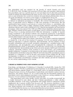
.push({});</script> </div> </div> </div> <div class="vf_link_relate px-2 my-2"> <h2 class="vf_doc_relate text-2xl font-bold my-4">Tài liệu liên quan</h2> <ul class="grid grid-cols-12 gap-2"> <li class="col-span-6 md:col-span-2"> <div class="card-doc " onclick="actionDocRelated(this)"> <a class="card-doc-img" href="https://text.123docz.net/document/1652866-absolute-c-4th-edition-part-2-pps.htm" title="Absolute C++ (4th Edition) part 2 pps"> <i class="icon i_type_doc i_type_doc2"></i> <img class="lazy" src="data:image/gif;base64,R0lGODlhAQABAIAAAP///wAAACH5BAEAAAAALAAAAAABAAEAAAICRAEAOw==" data-src="https://media.store123doc.com/images/document/2014_07/04/medium_yxu1404426060.jpg" width="124" height="179" alt="Absolute C++ (4th Edition) part 2 pps" onerror="this.src=)