Ebook Handbook of technical textiles: Part 2
Bạn đang xem bản rút gọn của tài liệu. Xem và tải ngay bản đầy đủ của tài liệu tại đây (249.36 KB, 20 trang )
<span class='text_page_counter'>(1)</span><div class='page_container' data-page=1>
<b>11</b>
<b>Textile-reinforced composite materials</b>
<b>Stephen L Ogin</b>
School of Mechanical and Materials Engineering, University of Surrey, Guildford,
GU2 7XH, UK
<b>11.1</b>
<b>Composite materials</b>
Textile-reinforced composite materials (TRCM) are part of the general class of
engineering materials called composite materials. It is usual to divide all
engineer-ing materials into four classes: metals, polymers, ceramics and composites. A
rigor-ous definition of composite materials is difficult to achieve because the first three
classes of homogeneous materials are sometimes heterogeneous at submicron
dimensions (e.g. precipitates in metals). A useful working definition is to say that
composite materials are characterised by being multiphase materials within which
the phase distribution and geometry has been deliberately tailored to optimise one
or more properties.1<sub>This is clearly an appropriate definition for textile-reinforced</sub>
composites for which there is one phase, called the matrix, reinforced by a fibrous
reinforcement in the form of a textile.
In principle, there are as many combinations of fibre and matrix available for
textile-reinforced composites as there are available for the general class of
com-posite materials. In addition to a wide choice of materials, there is the added factor
of the manufacturing route to consider, because a valued feature of composite
mate-rials is the ability to manufacture the article at the same time as the material itself
is being processed. This feature contrasts with the other classes of engineering
mate-rials, where it is usual for the material to be produced first (e.g. steel sheet) followed
by the forming of the desired shape.
</div>
<span class='text_page_counter'>(2)</span><div class='page_container' data-page=2>
chemical vapour infiltration and prepregging routes for ceramics. A reader
inter-ested in a general introduction to composite materials should consult one of a
number of wide ranging texts (e.g. Matthews and Rawlings,2<sub>Hull and Clyne,</sub>3<sub>). A</sub>
good introduction to the fabrication of polymer matrix composites is provided by
Bader<i>et al.</i>4
The market for composite materials can be loosely divided into two categories:
‘reinforced plastics’ based on short fibre E-glass reinforced unsaturated polyester
resins (which account for over 95% of the volume) and ‘advanced composites’ which
make use of the advanced fibres (carbon, boron, aramid, SiC, etc), or advanced
matrices (e.g. high temperature polymer matrices, metallic or ceramic matrices), or
advanced design or processing techniques.1<sub>Even within these loosely defined </sub>
cate-gories, it is clear that textile composites are ‘advanced composites’ by virtue of
the manufacturing techniques required to produce the textile reinforcement. This
chapter will be mostly concerned with textile-reinforced polymeric matrices.
The reader should be aware that ceramic fibres in a textile format which reinforce
ceramic matrices are also under investigation (e.g. Kuo and Chou,5 <sub>Pryce and</sub>
Smith6<sub>).</sub>
<b>11.2</b>
<b>Textile reinforcement</b>
<b>11.2.1</b> <b>Introduction</b>
Textile-reinforced composites have been in service in engineering applications
for many years in low profile, relatively low cost applications (e.g. woven
glass-reinforced polymer hulls for minesweepers). While there has been a continual
interest in textile reinforcement since around 1970, and increasingly in the 1980s, the
recent desire to expand the envelope of composite usage has had a dramatic effect on
global research into, and usage of, textile reinforcement. In addition to the possibility
of a range of new applications for which textile reinforcement could replace current
metal technology, textile reinforcement is also in competition with relatively mature
composite technologies which use the more traditional methods of prepregging and
autoclave manufacture. This is because TRCMs show potential for reduced
manu-facturing costs and enhanced processability, with more than adequate, or in some
cases improved, mechanical properties. Those economic entities within which
com-posite materials have been well developed, notably the European community (with
about 30% of global composite usage), the USA (with about 30%) and Japan (with
about 10%) have seen a growing interest in textile reinforcement in the 1990s, with
China, Taiwan, Russia, South Korea, India, Israel and Australia being additional
major contributors. In the last years of the 20th century, conferences devoted to
com-posite materials had burgeoning sessions on textile reinforcement.
Of the available textile reinforcements (woven, braided, knitted, stitched), woven
fabric reinforcement for polymer matrices can now be considered to be a mature
application, but many textiles are still the subject of demonstrator projects. For
example, a knitted glass fabric drawn over a mould and injected with a resin (using
the RTM technique) has been used to manufacture a door component for a
helicopter with the intention of replacing the current manufacturing route based on
autoclave processing of carbon fibre/epoxy resin prepreg material.7<sub>Several textile</sub>
</div>
<span class='text_page_counter'>(3)</span><div class='page_container' data-page=3>
For structural applications, the properties which are usually considered first are
stiffness, strength and resistance to damage/crack growth. The range of textiles
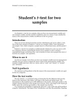
under development for composite reinforcement is indicated in the schematic
diagram shown in Fig. 11.1 from Ramakrishna.9<sub>The intention of the following </sub>
sec-tions is to give an introduction to textile-reinforced composite materials employing
woven, braided, knitted or stitched textile reinforcement. For more information, the
reader is referred to the relevant cited papers in the first instance. However, before
discussing textile-reinforced composites, it is necessary to provide an indication
of the degree of complexity of the mechanical properties of the more traditional
continuous fibre reinforcement of laminated composites. This discussion will also be
useful when textile reinforcement is discussed subsequently.
<b>11.2.2</b> <b>Basic mechanics of composite reinforcement</b>
<i>11.2.2.1</i> <i>Composites fabricated from continuous unidirectional fibres</i>
It is important to recognise that the macroscopic elastic stress–strain relationships
that are valid for isotropic materials are not valid for composite materials, except
in rare cases when isotropy has been deliberately engineered (e.g. quasi-isotropic
laminates loaded in-plane) or is a natural consequence of the material
microstruc-ture (e.g. transverse isotropy in the plane perpendicular to the fibre direction in a
lamina). In composite materials texts, the basic mechanics always begin with
con-tinuous unidirectional fibres reinforcing a matrix, with the explicit (or implicit)
assumption of a strong bond between matrix and fibre to enable good load
trans-ference from the matrix into the fibres (the detailed chemistry and properties of the
‘interphase’ region between fibre and bulk matrix is the subject of much research).
This is both a logical and a practical starting point because much traditional
composite fabrication uses sheets of reinforcing fibres preimpregnated with a resin
which is partially cured to facilitate handling. These ‘prepreg’ sheets, which are
usually about 0.125 mm thick, are stacked in appropriate orientations (depending
on the expected loading) and cured, usually in an oven under load or applied
pressure (autoclave processed), to produce the required component or part
(Fig. 11.2).
The Young’s modulus of a composite lamina parallel to the fibres,<i>E</i>1, is to a good
approximation (which ignores the difference in Poisson’s ratio between matrix
and fibre) given by the ‘rule of mixtures’ expression (sometimes called the Voigt
expression), which is:
(11.1)
where,<i>V</i>fis the fibre volume fraction in a void-free composite, and <i>E</i>fand<i>E</i>mare
the fibre and matrix moduli, respectively. Perpendicular to the fibres, the modulus
is given by:
(11.2)
which, for a given fibre volume fraction, is much lower than the rule of mixtures
expression. This is because the longitudinal modulus is fibre dominated and the
transverse modulus is matrix dominated.
<i>E</i>
<i>V</i>
<i>E</i>
<i>V</i>
<i>E</i>
2
1
1
=
+
-f
f
</div>
<span class='text_page_counter'>(4)</span><div class='page_container' data-page=4>
Textile preforms
Biaxial weaving
Triaxial weaving
Flat braiding
Circular braiding
Warp knitting
Weft knitting
Mechanical process
Chemical process
Knitting+weaving
Knitting+nonwoven
Lock stitching
Chain stitching
Biaxial weaving
Triaxial weaving
Multiaxial weaving
2 step braiding
4 step braiding
Solid braiding
Warp knitting
Weft knitting
Knitting+weaving
Knitting+stitching
Woven
Braid
Knit
Nonwoven
Combination
Stitched
Woven
Braid
Knit
Combination
2-Dimensional
preforms
3-Dimensional
preforms
<b>11.1</b> Textile techniques under development for composite materials.
Reprinted from S Ramakrishna,<i>Composites Sci. Technol</i>., 1997,<b>57</b>, 1–22,
</div>
<span class='text_page_counter'>(5)</span><div class='page_container' data-page=5>
The longitudinal strength of a composite lamina is also described by rule of
mix-tures expressions, though the precise form depends on which of the strains to failure,
matrix or fibres, is the larger. For example, if the strain to failure of the matrix
is larger, and the fibre volume fraction is typical of the range of engineering
com-posite materials (i.e. over 10% and up to about 70%), the comcom-posite strength,sc,
is given by:
sc= sfu<i>V</i>f (11.3)
wheresfuis the fibre strength.
Laminated composites will usually combine laminae with fibres at different
ori-entations. To predict the laminate properties, the stress–strain relations are required
for loading a lamina at an angle qto the fibre direction, and for loading both
in-plane and in bending. Composite mechanics for laminated composites is well
devel-oped and many textbooks deal with the subject (e.g. Jones,10 <sub>Matthews and</sub>
Rawlings,2<sub>Agarwal and Broutman</sub>11<sub>). For example, the modulus,</sub><i><sub>E</sub></i>
<i>x</i>, of a ply loaded
at an angle qto the fibre direction is given by:
(11.4)
where<i>E</i>1and<i>E</i>2have been defined above,n12is the principal Poisson’s ratio of the
lamina (typically 0.3) and <i>G</i>12is the in-plane shear modulus of the lamina. Unlike
isotropic materials, which require two elastic constants to define their elastic
stress–strain relationships, the anisotropy of a composite lamina (which is an
orthotropic material, i.e. it has three mutually perpendicular planes of material
symmetry) needs four elastic constants to be known in order to predict its in-plane
behaviour. The stress–strain relationships for a laminate can be predicted using
laminated plate theory (LPT), which sums the contributions from each layer in an
appropriate way for both in-plane and out-of-plane loading. Laminated plate theory
gives good agreement with measured laminate elastic properties for all types of
composite material fabricated from continuous unidirectional prepreg layers (UD).
Predicting laminate strengths, on the other hand, is much less reliable, except in
some simple cases, and is still the subject of ongoing research. Because composite
1 1 1 2 1
1
4
12
12
1
2 2
2
4
<i>Ex</i> <i>E</i> <i>G</i> <i>E</i> <i>E</i>
= cos q+Ê<sub>Ë</sub> - n ˆ<sub>¯</sub>sin qcos q+ sin q
“Interphase”
Fibre/Matrix
10mm <sub>Lamina</sub>
Laminate
<b>11.2</b> Schematic of the interphase around a fibre, a lamina (or prepreg sheet, typical
thickness 0.125 mm) and laminae stacked at different orientations to form a lamina.
</div>
<span class='text_page_counter'>(6)</span><div class='page_container' data-page=6>
structures are usually designed to strains below the onset of the first type of visible
damage in the structure (i.e. to design strains of about 0.3–0.4%), the lack of ability
to predict the ultimate strength accurately is rarely a disadvantage.
Ply orientations in a laminate are taken with reference to a particular loading
direction, usually taken to be the direction of the maximum applied load, which,
more often than not, coincides with the fibre direction to sustain the maximum load,
and this is defined as the 0° direction. In design it is usual to choose balanced
sym-metric laminates. A balanced laminate is one in which there are equal numbers of
+q and -qplies; a symmetric laminate is one in which the plies are symmetric in
terms of geometry and properties with respect to the laminate mid-plane. Hence
a laminate with a stacking sequence 0/90/+45/-45/-45/+45/90/0, which is written
(0/90/±45)sis both balanced and symmetric. Balanced symmetric laminates have a
simple response. In contrast, an unbalanced asymmetric laminate will, in general,
shear, bend and twist under a simple axial loading.
<i>11.2.2.2</i> <i>Overview of composite moduli for textile reinforcements</i>
One of the simplest laminate configurations for continuous unidirectional fibre
rein-forced composites is the cross-ply laminate, for example (0/90)s, which is 0/90/90/0.
For such a laminate, the Young’s moduli parallel to the 0° and 90° directions,<i>Ex</i>and
<i>Ey</i>, are equal and, to a good approximation, are just the average of <i>E</i>1and<i>E</i>2.
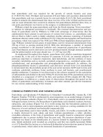
Yang and Chou12<sub>have shown schematically the change in these moduli,</sub><i><sub>E</sub></i>
<i>x</i>and
<i>Ey</i>, for a carbon fibre-reinforced epoxy laminate with a range of fibre architectures,
but the same fibre volume fraction of 60% (see Fig. 11.3). This diagram provides a
+
+
30
25
20
15
10
2
1
1 2 10 15 20 25 30
<i>Ey</i> (106 psi)
<i>Ex</i>
(10
6 psi)
10 25 50 100 150
150
100
50
25
10
<i>Ex</i>
(GPa)
<i>Ey</i> (GPa)
0°
q=15°
q=35°
<i>X</i>
<i>Y</i>
<i>Z</i>
±45°
90°
<i>y</i>
<i>x</i>
-q +q
Triaxial Fabric
Plain Weave
q
8-Harness Satin
0/90
<b>11.3</b> Predicted<i>Ex</i>and<i>Ey</i>moduli for a range of reinforcement architectures;±qangle ply
(forq =0 to ±45 to 90), cross-ply (0/90), eight-harness satin and plain woven, triaxial
woven fabric, braided (q =35° to 15°) and multiaxial warp knit (•--•), for the same fibre
volume fraction of 60%. Reprinted, with minor changes, from Yang and Chou,<i>Proceedings</i>
</div>
<span class='text_page_counter'>(7)</span><div class='page_container' data-page=7>
good starting point for the discussion of textile-reinforced composites. The cross-ply
composite has <i>Ex</i> and <i>Ey</i> moduli of about 75 GPa. In the biaxial weaves of the
eight-harness satin and the plain weave, the moduli both fall to about 58 GPa and
50 GPa, respectively. These reductions reflect the crimps in the interlaced woven
structure, with more crimps per unit length in the plain weave producing a smaller
modulus. The triaxial fabric, with three sets of yarns interlaced at 60° angles, behaves
similarly to a (0/±60)s angle-ply laminate. Such a configuration is quasi-isotropic
for in-plane loading, that is, it has the same Young’s modulus for any direction in
the plane of the laminate. The triaxial fabric shows a further reduction in <i>Ex</i>and<i>Ey</i>
to about 42 GPa, but this fabric benefits from a higher in-plane shear modulus
(which is not shown in the diagram) than the biaxial fabrics. The anticipated range
of properties for a multiaxial warp-knit fabric (or multilayer multidirectional
warp-knit fabric) reinforced composite is also shown, lying somewhere between
the triaxial fabric and above the cross-ply laminate (at least for the modulus <i>Ex</i>),
depending on the precise geometry. Here warp, weft and bias yarns (usually ±45)
are held together by ‘through-the-thickness’ chain or tricot stitching. Finally, a
three-dimensional braided composite is shown, with braiding angles in the range 15° to
35°. This type of fibre architecture gives very anisotropic elastic properties as shown
by the very high <i>Ex</i>moduli (which are fibre dominated) and the low <i>Ey</i>moduli
(which are matrix dominated). In the following sections, the properties of these
textile reinforcements (woven, braided, knitted, stitched) will be discussed in more
detail.
<b>11.3</b>
<b>Woven fabric-reinforced composites</b>
<b>11.3.1</b> <b>Introduction</b>
Woven fabrics, characterised by the interlacing of two or more yarn systems, are
cur-rently the most widely used textile reinforcement with glass, carbon and aramid
rein-forced woven composites being used in a wide variety of applications, including
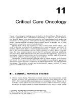
aerospace (Fig. 11.4). Woven reinforcement exhibits good stability in the warp and
<b>11.4</b> Optical micrograph of an eight-harness woven CFRP laminate showing damage in
the form of matrix cracks and associated delaminations. The laminate is viewed at a
polished edge. The scale bar is 200mm. Reprinted from F. Gao <i>et al</i>.,<i>Composites Sci.</i>
<i>Technol.</i>, 1999,<b>59</b>, 123–136, ‘Damage accumulation in woven fabric CFRP (carbon
fibre-reinforced plastic) laminates under tensile loading: Part 1 – Observations of damage,’
</div>
<span class='text_page_counter'>(8)</span><div class='page_container' data-page=8>
weft directions and offers the highest cover or yarn packing density in relation to
fabric thickness.13<sub>The possibility of extending the useful range of woven fabrics was</sub>
brought about by the development of carbon and aramid fibre fabrics with their
increased stiffness relative to glass. Prepreg manufacturers were able, by the early
1980s, to supply woven fabrics in the prepreg form familiar to users of nonwoven
material.14
There are a number of properties that make woven fabrics attractive compared
to their nonwoven counterparts. They have very good drapability, allowing complex
shapes to be formed with no gaps. Manufacturing costs are reduced since a single
biaxial fabric replaces two nonwoven plies and the ease of handling lends itself
more readily to automation. Woven fabric composites show an increased
resis-tance to impact damage compared to nonwoven composites, with significant
improvements in compressive strengths after impact. These advantages are gained,
however, at the expense of lower stiffness and strength than equivalent nonwoven
composites.
<b>11.3.2</b> <b>Mechanical behaviour</b>
<i>11.3.2.1</i> <i>Mechanical properties</i>
Bishop and Curtis16<sub>were amongst the first to demonstrate the potential advantages</sub>
of woven fabrics for aerospace applications. Comparing a five-harness woven
fabric (3k tows, which means 3000 carbon fibres per tow) with an equivalent
nonwoven carbon/epoxy laminate, they showed that the modulus of the biaxial
(0/90) woven laminate was slightly reduced compared to the nonwoven cross-ply
laminate (50 GPa compared to 60 GPa, respectively). The compressive strength
after a 7 J impact event was increased by over 30%. Similar results have been
found by others. For example, Raju <i>et al</i>.17<sub>found a decreasing modulus for carbon/</sub>
epoxy laminates moving from eight-harness (73 GPa) to five-harness (69 GPa)
to plain weave (63 GPa). These results are in line with the moduli changes
indicated in Fig. 11.3. The tensile strengths of woven composites are also slightly
lower than the nonwoven equivalents. Bishop and Curtis16 <sub>for example, found a </sub>
23% reduction in the tensile strength compared to UD equivalent laminates.
Triaxial woven fabric composites, naturally, have further reduced longitudinal
properties, as mentioned earlier. Fujita <i>et al</i>.18 <sub>quote a Young’s modulus and </sub>
tensile strength of 30 GPa and 500 MPa, respectively, for a triaxial woven carbon/
epoxy.
Glass-reinforced woven fabrics give rise naturally to composites with lower
mechanical properties because of the much lower value of the glass fibre modulus
compared to carbon. Amijima <i>et al.</i>19<sub>report Young’s modulus and tensile strength</sub>
values for a plain weave glass/polyester (<i>V</i>f=33%) of 17 GPa and 233 MPa,
respec-tively, while Boniface <i>et al.</i>20<sub>find comparable values for an eight-harness glass/epoxy</sub>
composite, that is, 19 GPa and 319 MPa, respectively (<i>V</i>f=37%).
</div>
<span class='text_page_counter'>(9)</span><div class='page_container' data-page=9>
accumu-lation under static and cyclic loading is different in laminates fabricated from twisted
or untwisted yarn.22
<i>11.3.2.2</i> <i>Damage accumulation</i>
Damage under tensile loading in woven composites is characterised by the
development of matrix cracking in the off-axis tows at strains well above about
0.3–0.4%. Most investigations of damage have considered biaxial fabrics loaded in
the warp direction. Cracks initiate in the weft bundles and an increasing density
of cracks develops with increasing load (or strain). The detailed crack
morphol-ogy depends on whether the tows are twisted or untwisted. Twisted tows lead to
fragmented matrix cracks; untwisted tows lead to matrix cracks, which strongly
resemble the 90 ply cracks that develop in cross-ply laminates.22,23<sub>The accumulation</sub>
of cracks is accompanied by a gradual decrease in the Young’s modulus of
the composite. In woven carbon systems, the matrix cracking can lead to
con-siderable delamination in the region of the crimps in adjacent tows which further
reduces the mechanical properties.15 <sub>Damage modelling has been attempted </sub>
using finite element methods (e.g. Kriz,24 <sub>Kuo and Chou</sub>5<sub>) or closed-form models </sub>
(e.g. Gao et al.25<sub>).</sub>
<b>11.3.3</b> <b>Analyses of woven composites</b>
The majority of closed-form analyses of woven fabric composites have a
substan-tial reliance on laminated plate theory. Numerical methods rely on the finite element
method (FEM).
In a series of papers in the early 1980s by Chou, Ishikawa and co-workers (see
Chou26<sub>for a comprehensive review) three models were presented to evaluate the</sub>
thermomechanical properties of woven fabric composites. The mosaic model treats
the woven composite as an assemblage of assymetric cross-ply laminates, ignoring
the fibre continuity and undulation. The fibre undulation model takes these
com-plexities into account by considering a slice of the crimped region and averaging
the properties with the aid of LPT. This model is particularly appropriate for plain
and twill weave composites. For five-harness and eight-harness satins, the fibre
undu-lation model is broadened in the bridging model. These essentially one-dimensional
models have been extended to two dimensions by Naik and co-workers (e.g. Naik
and Shembekar21<sub>).</sub>
</div>
<span class='text_page_counter'>(10)</span><div class='page_container' data-page=10>
<b>11.4</b>
<b>Braided reinforcement</b>
<b>11.4.1</b> <b>Introduction</b>
Braided textiles for composites consist of intertwined two (or more) sets of yarns,
one set of yarns being the axial yarns. In two-dimensional braiding, the braided yarns
are introduced at ±q directions and the intertwining is often in 1 ¥ 1 or 2 ¥ 2
patterns (see Fig. 11.5).29,30 <sub>However, for significant improvements in </sub>
through-the-thickness strength, three-dimensional braided reinforcement is an important
category (e.g. Du <i>et al.</i>31<sub>). The braided architecture enables the composite to endure</sub>
twisting, shearing and impact better than woven fabrics. Combined with low cost
fabrication routes, such as resin transfer moulding, braided reinforcements are
expected to become competitor materials for many aerospace applications (where
they may replace carbon prepreg systems) or automobile applications (e.g. in energy
absorbing structures), although realisation in practice is currently limited.
A variety of shapes can be fabricated for composite applications from hollow
tubular (with in-laid, non-intertwined yarns) to solid sections, including I-beams. The
stability or conformability of the braided structure depends on the detailed fibre
architecture. With in-laid yarns, for example, stability in the 0° direction in tension
is improved, though the axial compressive properties may be poor.13 <sub>In general</sub>
terms, the mechanical properties of composites fabricated using braided
reinforce-ment depend on the braid parameters (braid architecture, yarn size and spacing,
fibre volume fraction) and the mechanical properties of fibre and matrix.
<b>11.4.2</b> <b>Mechanical behaviour</b>
In this section, two-dimensional braided reinforcement will be considered
primar-ily, since it lends itself to direct comparison with laminated composites with a 0/±q
construction and such comparisons have been made by a number of authors. For
<b>11.5</b> Braided two-dimensional reinforcement; the pattern is a 2 ¥2 braid. Reprinted from
</div>
<span class='text_page_counter'>(11)</span><div class='page_container' data-page=11>
example, Naik and co-workers29 <sub>manufactured braided carbon fibre-reinforced</sub>
epoxy resin composites with a number of fibre architectures while maintaining a
constant fibre volume fraction (<i>V</i>f=56%) overall. By keeping the axial yarn content
constant, but varying the yarn size or braid angle, the effect of each variable on
composite properties could be investigated. An insensitivity to yarn size was found
(in the range of 6–75 k tow size), but the braid angle had a significant effect, as
antici-pated. A modest increase in longitudinal modulus (from 60–63 GPa) occurred in
moving from a braid architecture of 0/±70 to 0/±45, with a much larger fall in
trans-verse modulus (from 46–19 GPa).
The strengths of braided reinforced composites are lower than their prepregged
counterparts. Norman <i>et al.</i>32<sub>compared the strengths of 0/</sub><sub>±</sub><sub>45 braided composites</sub>
with an equivalent prepreg (UD) system, finding that the prepreg system had
a tensile strength that was some 30% higher than the braided two-dimensional
composite (849 MPa compared to 649 MPa). Similar results found by Herszberg
<i>et al.</i>(1997) have been attributed to fibre damage during braiding. Norman <i>et al</i>.32
also found the braided reinforcement to be notch insensitive for notch sizes up to
12 mm, whereas equivalent UD laminates showed a significant notch sensitivity in
this range. Compression after impact tests also favour braided composites when
nor-malised by the undamaged compression strengths, in comparison with UD systems.
Indeed, the ability to tailor the braided reinforcement to have a high energy
absorb-ing capability may make them of use in energy-absorbent structures for crash
situ-ations.33<sub>A review by Bibo and Hogg</sub>34<sub>discusses energy-absorbing mechanisms and</sub>
postimpact compression behaviour of a wide range of reinforcement architectures,
including braided reinforcement.
<b>11.4.3</b> <b>Analyses of braided reinforcement</b>
The potential complexity of the braided structure, particularly the
three-dimensional architectures, is such that the characterisation of structures is often
taken to be a major first step in modelling the behaviour of the reinforced
mater-ial. The desired outcome of this work is to present a three-dimensional visualisation
of the structure (e.g. Pandey and Hahn35<sub>) or to develop models to describe the </sub>
struc-tural geometry (e.g. Du <i>et al.</i>31<sub>). Analytical models for predicting properties are </sub>
fre-quently developments of the fibre-crimp model developed by Chou26<sub>and colleagues</sub>
for woven reinforcements, extended in an appropriate way by treating a
represen-tative ‘unit cell’ of the braided reinforcement as an assemblage of inclined
unidi-rectional laminae (e.g. Byun and Chou36<sub>). Micromechanics analyses incorporated</sub>
into personal computer-based programs have also been developed (e.g. the Textile
composite analysis for design, TEXCAD; see e.g. Naik37<sub>).</sub>
<b>11.5</b>
<b>Knitted reinforcement</b>
<b>11.5.1</b> <b>Introduction</b>
</div>
<span class='text_page_counter'>(12)</span><div class='page_container' data-page=12>
nature of the reinforcing fibres/yarns which permits the fabric to have the
stretch-ability to adapt to complex shapes without crimp (Fig. 11.6). However, the
advan-tages which the knitted fibre architecture brings also lead to the disadvanadvan-tages,
which are the reduced in-plane stiffness and strength of the composites caused by
the relatively poor use of the mechanical properties of the fibre (glass, carbon or
aramid). Weft and warp knits can, however, be designed with enhanced properties
in certain directions by the use of laid-in yarns.13
Both warp-knitted and weft-knitted reinforcements are under investigation. In
general terms, the weft-knitted structures are preferred in developmental work
owing to their superior formability (based on their less stable structure) and
warp-knitted structures are preferred for large scale production (owing to the increased
production rate allowed by the knitting of many yarns at one time).7
<b>11.5.2</b> <b>Mechanical behaviour</b>
<i>11.5.2.1</i> <i>Mechanical properties</i>
The tensile and compressive properties of the knitted fabrics are poor in
compari-son with the other types of fabric already discussed, but they are more likely to be
chosen for their processability and energy-absorbing characteristics than their basic
in-plane properties.
The detailed fibre architecture of knitted fabric reinforcement leads to
in-plane properties which can either be surprisingly isotropic or very anisotropic. For
example, Bannister and Herszberg38<sub>tested composites manufactured using both a</sub>
full-milano and half-milano knitted glass-reinforced epoxy resin. The full-milano
structure was significantly more random in its architecture than the half-milano, with
the consequence that the tensile strengths in both the wale and the course
direc-tions were approximately the same. Typically, the stress–strain curve is
approxi-mately linear to a strain of about 0.6%,39<sub>followed by a sharp knee and pseudoplastic</sub>
behaviour to failure. The tensile strengths were proportional to the fibre volume
fraction (in a manner which is understandable based on a rule-of-mixtures
predic-Course
W
ale
<b>11.6</b> Schematic diagrams of (a) weft-knitted and (b) warp-knitted reinforcement.
Reprinted from S Ramakrishna,<i>Composites Sci. Technol.</i>, 1997,<b>57</b>1–22, with permission
from Elsevier Science.9
</div>
<span class='text_page_counter'>(13)</span><div class='page_container' data-page=13>
tion of composite strength; and see Section 5.3 below), with a typical value being
about 145 MPa for a fibre volume fraction of 45%. However, the strains to failure
were not only very large (in the range from about 2.8% for seven cloth layers to
about 6.6% for 12 cloth layers) but also increased with number of layers/fibre
volume fraction. The reasons for this variation are presumably related to the
detailed manner in which the damage accumulates to produce failure in the
com-posites. In contrast to the relatively isotropic full-milano reinforcement, the
half-milano knitted architecture, which has a higher degree of fibre orientation, showed
tensile strengths which varied by 50% in the two directions and difference in strains
to failure which were even larger (about a factor of two).
Knitted carbon reinforcement has been investigated by Ramakrishna and Hull.40
In general, the weft-knitted composites showed moduli which increased roughly
lin-early with fibre volume fraction, being typically 15 GPa when tested in the wale
direction and 10 GPa when tested in the course direction, for a fibre volume
frac-tion of about 20%. Tensile strengths also increase in a similar fashion for the wale
direction (a typical value is 60 MPa for a 20% volume fraction), whereas the course
direction strengths are reasonably constant with fibre volume fraction at around
34 MPa. These differences are related to the higher proportion of fibre bundles
oriented in the wale direction.
In compression, the mechanical properties are even less favourable. For both the
half-milano and full-milano glass-reinforced composites39<sub>the compression strengths</sub>
showed features which are a consequence of the strong dominance of the matrix in
compression arising from the highly curved fibre architecture. These features are
manifest as compression strengths that were approximately the same in both wale
and course directions and as a compression strength that only increased by about
15% as the fibre volume fraction increased from 29–50% (interestingly, the
com-pression strengths were found to be consistently higher than the tensile strengths,
by up to a factor of two). In the light of these results, it is not surprising that
deform-ing the knitted fabric by strains of up to 45% prior to infiltration of the resin and
consolidation of the composite has virtually no effect on the composite
compres-sive strength.41
Similar findings have been reported by others. Wang <i>et al.</i>42<sub>tested a 1 </sub><sub>¥</sub><sub>1 rib-knit</sub>
structure of weft-knitted glass-reinforced epoxy resin, finding compressive strengths
which were almost twice as high as the tensile strengths. The relatively isotropic
nature of this fibre architecture led to Young’s modulus values and Poisson’s ratio
values which were also approximately the same for testing in both the wale and
course direction.
<i>11.5.2.2</i> <i>Damage accumulation</i>
There are a large number of potential sites for crack initiation in knitted
com-posites. For example, observations on weft-knitted composites tested in the wale
direction suggest that cracks initiate from debonds which form around the needle
and sinker loops in the knitted architecture. Similarly, crack development in fabrics
tested in tension in the course direction is believed to occur from the sides (or legs)
of loops.39,40<sub>It appears likely that crack linking will occur more readily for cracks</sub>
initiated along the legs of the loops (i.e. when the composite is loaded in the course
direction) than when initiation occurs at the needle and sinker loops.
</div>
<span class='text_page_counter'>(14)</span><div class='page_container' data-page=14>
impact energy in the range 0–10 J is absorbed by a weft-knitted glass reinforced
composite (<i>V</i>f=50%) than was absorbed by an equivalent woven fabric.
Observa-tions indicated, in addition, that the damaged area was approximately six times
larger for the knitted fabric than for the woven fabric, presumably reflecting the
increased availability of crack initiation sites in the knitted architecture.
Compres-sion after impact (CAI) strengths were decreased by only 12% for the knitted fabric
in this impact energy range, whereas the woven fabric CAI values fell by up to
40%.38
<b>11.5.3</b> <b>Analyses of knitted composites</b>
Models for the elastic moduli and tensile strengths of knitted fabric reinforced
com-posites have been developed (e.g. Ramakrishna,9<sub>Gommers</sub><i><sub>et al.</sub></i>43,44<sub>). Ramakrishna,</sub>
for example, divides a weft-knitted fabric architecture into a series of circular arcs
with each yarn having a circular cross-section. It is then possible to derive an
expres-sion for the Young’s modulus of the composite by integrating the expresexpres-sion for the
variation in Young’s modulus with angle (equation 11.4) along the required
direc-tions. Indeed, all the elastic moduli can be calculated in a similar fashion, although
the predictions were about 20% higher than the experimental results. The
predic-tions of tensile strength depend on the expression for the strength of an aligned
fibre composite modified by terms which attempt to account for the average
orien-tation of the yarns with respect to the loading direction and the statistical variation
of the bundle strengths. The tensile strengths are predicted to scale in proportion to
the fibre volume fractions in both the wale and course directions, which is exactly
the result found by Leong <i>et al</i>.39<sub>Gommers</sub><i><sub>et al.</sub></i>43,44<sub>use orientation tensors to </sub>
rep-resent fibre orientation variations in the fabric.
<b>11.6</b>
<b>Stitched fabrics</b>
<b>11.6.1</b> <b>Introduction</b>
Stitching composites is seen as a direct approach to improving the
through-the-thickness strength of the materials. This in turn will improve their damage tolerance,
and particularly the CAI behaviour, where failure is usually triggered by
microbuck-ling in the vicinity of a delamination. In its simplest form, stitching of composites
adds one further production step with the use of a sewing machine to introduce lock
stitches through the full thickness of the laminate. The stitching can be performed
on unimpregnated fibres or fibres in the prepreg form, although the latter is usually
to be avoided owing to excessive fibre damage. Stitching in this way can be carried
out with carbon, glass or aramid fibre yarns. In its more sophisticated form, chain
or tricot stitches are used to produce a fabric which consists of warp (0°), weft (90°)
and (optionally) bias (±q) yarns held together by the warp-knitted stitches, which
usually consist of a light polyester yarn (Fig. 11.7). The resulting fabric is called a
non-crimp fabric (NCF) or a multiaxial warp-knit fabric (MWK) (see e.g. Hogg
<i>et al.,</i>45<sub>Du and Ko</sub>46<sub>). Whatever the terminology, the warp-knitted fabrics are highly</sub>
</div>
<span class='text_page_counter'>(15)</span><div class='page_container' data-page=15>
from a tool owing to the ability of the stitching to allow sufficient relative
move-ment of the tows.47<sub>With the potential for combining the fabric with low-cost </sub>
fabri-cation routes (e.g. RTM), these fabrics are expected both to broaden the envelope
of composite usage and to replace the more expensive prepregging route for many
applications. The ability to interdisperse thermoplastic fibres amongst the
reinforc-ing fibres also provides a potentially very attractive manufacturreinforc-ing route.47<sub>Hence,</sub>
this brief introduction will concentrate on the warp-knitted materials. A
compre-hensive review of the effect of all types of stitching on delamination resistance has
been published by Dransfield <i>et al.</i>48
<b>11.6.2</b> <b>Mechanical behaviour</b>
<i>11.6.2.1</i> <i>Mechanical properties</i>
The basic mechanical properties of NCFs are somewhat superior to the equivalent
volume fraction of woven roving-reinforced material. For example, Hogg <i>et al.</i>45
find the Young’s modulus and tensile strength of a biaxial NCF glass-reinforced
polyester, volume fraction 33%, to be 21 GPa and 264 MPa, respectively, which are
values some 13 and 20% higher than those found for an equivalent volume fraction
of plain woven-reinforced composite (see Section 11.3.2.1; Amijima <i>et al.</i>,19<sub>).</sub>
Quadriaxial reinforcement of the same fibre volume fraction gave similar results
(24 GPa and 286 MPa, respectively). The improvement in properties compared
to woven-reinforced composites is emphasised by the work of Godbehere <i>et al.</i>49
in tests on a carbon fibre-reinforced NCF epoxy resin and equivalent
unidirec-tional (UD) laminates. All the composites had 0/±45 orientations. Although the
NCF laminates had poorer properties than the UD laminates, the reduction
was small (e.g. less than 7%) in the 0° direction. For example, the UD equivalent
laminate gave values of Young’s modulus and tensile strength of 58 GPa and
<i>Stitch</i>
Cotech®
<i>Quadriaxial</i>
</div>
<span class='text_page_counter'>(16)</span><div class='page_container' data-page=16>
756 MPa, respectively, compared to NCF values of 56 GPa and 748 MPa (for fibre
volume fractions of 56%).
The increases in through-the-thickness reinforcement achieved by NCFs have
been demonstrated by a number of authors. For example, Backhouse <i>et al.</i>50<sub></sub>
com-pared the ease of delaminating polyester stitched 0/±45 carbon fibre NCF with
equivalent carbon fibre/epoxy UD laminates. There were large increases, some
140%, in the measured parameters used to quantify resistance to delamination (the
mode I and mode II toughness values) for the NCF fabrics compared to the UD
material.
<i>11.6.2.2</i> <i>Damage accumulation</i>
Owing to the fact that the fibres in each layer in an NCF-reinforced composite are
parallel, it is to be expected that the damage accumulation behaviour is very similar
to equivalent UD laminates. Indeed, Hogg <i>et al.</i>45 <sub>found the matrix cracking in</sub>
biaxial glass NCF to be very similar to matrix cracking in the 90° ply of cross-ply
UD laminates. There are, however, microstructural features introduced because of
the knitting yarn which do not have parallels in UD laminates. Local variations in
fibre volume fraction, resin-rich pockets and fibre misalignment provide significant
differences. In biaxial reinforced NCFs, for example, transverse cracks can initiate
preferentially where the interloops of the knitted yarn intersect the transverse ply.51
<b>11.6.3</b> <b>Analyses of non-crimp fabrics</b>
For in-plane properties of NCF composites, it is likely that there is sufficient
simi-larity to UD materials to enable similar analyses to be used (although Hogg <i>et al.</i>45
suggest that the properties of NCF composites may exceed the in-plane properties
of UD equivalents). However, detailed models of the three-dimensional structure
of NCF-based composites for manufacturing purposes (i.e. for determining process
windows for maximum fibre volume fractions, for example) and for the prediction
of mechanical properties, are being developed (e.g. Du and Ko46<sub>).</sub>
<b>11.7</b>
<b>Conclusion</b>
The 1990s saw a growing mood of cautious optimism within the composites
com-munity worldwide that textile-based composites will give rise to new composite
material applications in a wide range of areas. Consequently, a wide range of
textile-reinforced composites are under development/investigation or in production.
Textile reinforcement is thus likely to provide major new areas of opportunity for
composite materials in the future.
<b>References</b>
1. m g bader, Short course notes for ‘<i>An introduction to composite materials</i>,’ University of Surrey, 1997.
2. f l matthewsandr rawlings,<i>Composite Materials: Engineering and Science</i>, Chapman and Hall,
London, 1994.
3. d hullandt w clyne,<i>An Introduction to Composite Materials</i>, Cambridge University Press,
Cam-bridge, 1996.
</div>
<span class='text_page_counter'>(17)</span><div class='page_container' data-page=17>
<i>Ency-clopedia – Volume 3, Processing and Fabrication Technology</i>, Technomic Publishing, Lancaster,
Pennsylvania, USA, 1990.
5. w-s kuoandt-w chou, ‘Elastic response and effect of transverse cracking in woven fabric brittle
matrix composites’,<i>J. Amer. Ceramics Soc</i>. 1995 78(3) 783–792.
6. a w pryceandp a smith, ‘Behaviour of unidirectional and crossply ceramic matrix composites under
quasi-static tensile loading’,<i>J. Mater. Sci</i>., 1992 272695–2704.
7. k h leong,s ramakrishnaandh hamada, ‘The potential of knitting for engineering composites’, in
<i>Proceedings of 5th Japan SAMPE Symposium</i>, Tokyo, Japan, 1997.
8. a nakai,m masuiandh hamada, ‘Fabrication of large-scale braided composite with I-shaped
struc-ture’, in<i>Proceedings of the 11th International Conference on Composite Materials</i>(ICCM-11), Gold
Coast, Queensland, Australia, published by Australian Composites Structures Society and Woodhead
Publishing, 1997, 3830–3837.
9. s ramakrishna, ‘Characterization and modeling of the tensile properties of plain weft-knit
fabric-reinforced composites’,<i>Composites Sci. Technol.</i>, 1997 571–22.
10. r m jones,<i>Mechanics of Composite Materials</i>, Scripta (McGraw-Hill), Washington DC, 1975.
11. b d agarwalandl j broutman,<i>Analysis and Performance of Fiber Composites</i>, John Wiley and Sons,
New York, 1980.
12. j-m yangandt-w chou, ‘Performance maps of textiles structural composites’, in <i>Proceedings of Sixth</i>
<i>International Conference on Composite Materials and Second European Conference on Composite</i>
<i>Materials (ICCM6/ECCM2)</i>eds F L Matthews, N C R Buskell, J M Hodgkinson and J Morton,
Elsevier, London, 1987, 5.579–5.588.
13. f scardino, ‘An introduction to textile structures and their behaviour’, in <i>Textile Structural </i>
<i>Composites</i>, Chapter 1,<i>Composite Materials Series </i>Vol 3, eds T W Chou and F K Ko, Elsevier, Oxford
1989.
14. j a baillie, ‘Woven fabric aerospace structures’, in <i>Handbook of Fibre Composites</i>, eds C T
Herakovich and Y M Tarnopol’skii, Elsevier Science, Oxford 1989, Vol 2, 353–391.
15. f gao,l boniface,s l ogin,p a smithandr p greaves, ‘Damage accumulation in woven fabric
CFRP laminates under tensile loading. Part 1: Observations of damage; Part 2: Modelling the
effect of damage on macromechanical properties’, <i>Composites Sci. Technol.</i>, 1999 <b>59</b> 123–
136.
16. s m bishopandp t curtis, ‘An assessment of the potential of woven carbon fibre reinforced plastics
for high performance applications’,<i>Composites</i>, 1984 15259–265.
17. i s raju,r l foyeandv s avva, ‘A review of analytical methods for fabric and textile composites’, in
<i>Proceedings of the Indo-US Workshop on Composites for Aerospace Applications</i>: Part 1, Bangalore,
India, 1990, 129–159.
18. a fujita,h hamadaandz maekawa, ‘Tensile properties of carbon fibre triaxial woven fabric
com-posites’,<i>J. Composite Mat</i>., 1993 271428–1442.
19. s amijima,t fujiiandm hamaguchi, ‘Static and fatigue tests of a woven glass fabric composite under
biaxial tension-tension loading’,<i>Composites</i>, 1991 22281–289.
20. l boniface,s l oginandp a smith, ‘Damage development in woven glass/epoxy laminates under
tensile load’, in<i>Proceedings 2nd International Conference on Deformation and Fracture of </i>
<i>Com-posites</i>, Manchester, UK, Plastics and Rubber Institute, London 1993.
21. n k naikandp s shembekar, ‘Elastic behaviour of woven fabric composites: I – lamina analysis’,<i>J.</i>
<i>Composite Mater.</i>, 1992<b>26</b>2196–2225.
22. w marsden,l boniface,s l oginandp a smith, ‘Quantifying damage in woven glass fibre/epoxy
lam-inates,’ in Proceedings <i>FRC ’94</i>, Sixth International Conference on Fibre Reinforced Composites,
Newcastle upon Tyne, Institute of Materials, 1994, paper 31, pp. 31/1–31/9.
23. w marsden, ‘Damage accumulation in a woven fabric composite’, PhD Thesis, University of Surrey,
1996.
24. r d kriz, ‘Influence of damage on mechanical properties of woven fabric composites’,<i>J. Composites</i>
<i>Technol. Res.</i>, 1985 755–58.
25. f gao,l boniface,s l ogin,p a smithandr p greaves, ‘Damage accumulation in woven baric CFRP
laminates under tensile loading. Part 2: Modelling the effect of damage on macro-mechanical
properties’,<i>Composites Sci. Technol.</i>, 1999 59137–145.
26. t w chou,<i>Microstructural Design of Fiber Composites</i>, Cambridge Solid State Science Series,
Cambridge University Press, 1992.
27. e h glaessgenando h griffin jr, Finite element based micro-mechanics modeling of textile
com-posites, NASA Conference Publication 3311, Part 2:<i>Mechanics of Textile Composites Conference</i>,
Langley Research Centre, eds C C Poe and C E Harris, 1994, 555–587.
28. k wooandj whitcomb, ‘Global/local finite element analysis for textile composites’,<i>J. Composite</i>
<i>Mater.</i>, 1994 281305–1321.
29. r a naik,p g ifjuandj e masters, ‘Effect of fiber architecture parameters on deformation fields and
elastic moduli of 2-D braided composites’,<i>J. Composite Mater.</i>, 1994 28656–681.
30. p tan, l tong and g p steven, ‘Modelling for predicting the mechanical properties of textile
</div>
<span class='text_page_counter'>(18)</span><div class='page_container' data-page=18>
31. g-w du,t-w chouandpopper, ‘Analysis of three-dimensional textile preforms for multidirectional
reinforcement of composites’,<i>J. Mater. Sci.</i>, 1991 263438–3448.
32. t l norman,c anglinandd gaskin, ‘Strength and damage mechanisms of notched two-dimensional
triaxial braided textile composites and tape equivalents under tension’,<i>J. Composites Technol. Res.</i>,
1996<b>18</b>38–46.
33. i herszberg,m k bannister,k h leongandp j falzon, ‘Research in textile composites at the
Coop-erative Research Centre for Advanced Composite Structures Ltd’,<i>J. Textile Inst</i>., 1997 8852–67.
34. g a biboandp j hogg, ‘Role of reinforcement architecture on impact damage mechanisms and
post-impact compression behaviour – a review’,<i>J. Mater. Sci.</i>, 1996 311115–1137.
35. r pandeyandh t hahn, ‘Visualization of representative volume elements for three-dimensional
four-step braided composites,’ <i>Composites Sci. Technol.</i>, 1996 56161–170.
36. j-h byunandt-w chou, ‘Modelling and characterization of textile structural composites: a review’,
<i>J. Strain Anal.</i>, 1989 2465–74.
37. r a naik, ‘Failure analysis of woven and braided fabric reinforced composites’,<i>J. Composite Mater.</i>,
1995<b>29</b>2334–2363.
38. m bannisterandi herszberg, ‘The manufacture and analysis of composite structures from knitted
preforms’, in <i>Proceedings 4th International Conference on Automated Composites</i>, Nottingham, UK,
Institute of Materials, 1995.
39. k h leong,p j falzon,m k bannisterandi herszberg, ‘An investigation of the mechanical
perfor-mance of weft knitted milano rib glass/epoxy composites’,<i>Composites Sci. Technol.</i>, 1998 58239–251.
40. s ramakrishnaandd hull, ‘Tensile behaviour of knitted carbon-fibre fabric/epoxy laminates – Part
I: Experimental’,<i>Composites Sci. Technol</i>., 1994 50237–247.
41. m nguyen,k h leongandi herszberg, ‘The effects of deforming knitted glass preforms on the
composite compression properties’, in <i>Proceedings 5th Japan SAMPE Symposium</i>, Tokyo, Japan,
1997.
42. y wang,y gowayed,x kong,j liandd zhao, ‘Properties and analysis of composites reinforced with
E-glass weft-knitted fabrics’,<i>J. Composites Technol. Res</i>., 1995 17283–288.
43. b gommers,i verpoestandp van houtte, ‘Analysis of knitted fabric reinforced composites: Part 1.
Fibre distribution’,<i>Composites</i>, 1998 29A1579–1588.
44. b gommers,i verpoestandp van houtte, ‘Analysis of knitted fabric reinforced composites: Part II.
Stiffness and strength’,<i>Composites</i>, 1998 29A1589–1601.
45. p j hogg,a ahmadniaandf j guild, ‘The mechanical properties of non-crimped fabric-based
com-posites’,<i>Composites</i>, 1993 24423–432.
46. g-w duandf ko, ‘Analysis of multiaxial warp-knit preforms for composite reinforcement,’ <i></i>
<i>Com-posites Sci. Technol.</i>, 1996 56253–260.
47. p j hoggandd h woolstencroft, ‘Non-crimp thermoplastic composite fabrics: aerospace solutions
to automotive problems’, in <i>Proceeding of 7th Annual ASM/ESD Advanced Composites Conference,</i>
<i>Advanced Composite Materials: New Developments and Applications </i>Detroit, Michigan, 1991,
339–349.
48. k dransfield,c baillieandy-w mai, ‘Improving the delamination resistance of CFRP by stitching
– a review’,<i>Composites Sci. Technol.</i>, 1994 50305–317.
49. a p godbehere,a r millsandp irving, Non crimped fabrics versus prepreg CFRP composites – a
comparison of mechanical performance, in Proceedings Sixth International Conference on Fibre
Reinforced Composites,<i>FRC ’94</i>, University of Newcastle upon Tyne, Institute of Materials
Con-ference, 1994, pp 6/1–6/9.
50. r backhouse,c blakemanandp e irving, ‘Mechanisms of toughness enhancement in carbon-fibre
non-crimp fabrics’, in <i>Proceedings 3rd International Conference on Deformation and Fracture of</i>
<i>Composites</i>, held at University of Surrey, Guildford, UK, published by Institute of Materials, 1995,
307–316.
51. s sandford,l boniface,s l ogin,s anand,d brayandc messenger, ‘Damage accumulation in
non-crimp fabric based composites under tensile loading’, in <i>Proceedings Eighth European Conference</i>
</div>
<span class='text_page_counter'>(19)</span><div class='page_container' data-page=19>
<b>12</b>
<b>Waterproof breathable fabrics</b>
<b>David A Holmes</b>
Faculty of Technology, Department of Textiles, Bolton Institute, Deane Road,
Bolton BL3 5AB, UK
<b>12.1</b>
<b>What are waterproof breathable fabrics?</b>
Waterproof breathable fabrics are designed for use in garments that provide
pro-tection from the weather, that is from wind, rain and loss of body heat. Clothing
that provides protection from the weather has been used for thousands of years.
The first material used for this purpose was probably leather but textile fabrics have
also been used for a very long time. Waterproof fabric completely prevents the
penetration and absorption of liquid water, in contrast to water-repellent (or,
shower-resistant) fabric, which only delays the penetration of water. Traditionally,
fabric was made waterproof by coating it with a continuous layer of impervious
flex-ible material. The first coating materials used were animal fat, wax and hardened
vegetable oils. Nowadays synthetic polymers such as polyvinylchloride (PVC) and
polyurethane are used. Coated fabrics are considered to be more uncomfortable to
wear than water-repellent fabric, as they are relatively stiff and do not allow the
escape of perspiration vapour. Consequently they are now used for ‘emergency’
rainwear. Water-repellent fabric is more comfortable to wear but its water-resistant
properties are short lived.
The term ‘breathable’ implies that the fabric is actively ventilated. This is not the
case. Breathable fabrics passively allow water vapour to diffuse through them yet
still prevent the penetration of liquid water.1<sub>Production of water vapour by the skin</sub>
is essential for maintenance of body temperature. The normal body core
tempera-ture is 37 °C, and skin temperatempera-ture is between 33 and 35 °C, depending on
condi-tions. If the core temperature goes beyond critical limits of about 24 °C and 45 °C
then death results. The narrower limits of 34 °C and 42 °C can cause adverse effects
such as disorientation and convulsions. If the sufferer is engaged in a hazardous
pastime or occupation then this could have disastrous consequences.
</div>
<span class='text_page_counter'>(20)</span><div class='page_container' data-page=20>
becomes uncomfortable. In extreme cases hypothermia can result if the body loses
heat more rapidly than it is able to produce it, for example when physical activity
has stopped, causing a decrease in core temperature. If perspiration cannot
evapo-rate and liquid sweat (sensible perspiration) is produced, the body is prevented from
cooling at the same rate as heat is produced, for example during physical activity,
and hyperthermia can result as the body core temperature increases. The heat
energy produced during various activities and the perspiration required to provide
adequate body temperature control have been published.2,3<sub>Table 12.1 shows this</sub>
information for activities ranging from sleeping to maximum work rate.
If the body is to remain at the physiologically required temperature, clothing has
to permit the passage of water vapour from perspiration at the rates under the
activ-ity conditions shown in Table 12.1. The abilactiv-ity of fabric to allow water vapour to
penetrate is commonly known as breathability. This property should more
scientifi-cally be referred to as water vapour permeability. Although perspiration rates and
water vapour permeability are usually quoted in units of grams per day and grams
per square metre per day, respectively, the maximum work rate can only be endured
for a very short time.
During rest, most surplus body heat is lost by conduction and radiation, whereas
during physical activity, the dominant means of losing excess body heat is by
evapo-ration of perspievapo-ration. It has been found that the length of time the body can
endure arduous work decreases linearly with the decrease in fabric water vapour
permeability. It has also been shown that the maximum performance of a subject
wearing clothing with a vapour barrier is some 60% less than that of a subject
wearing the same clothing but without a vapour barrier. Even with two sets of
cloth-ing that exhibit a small variation in water vapour permeability, the differences in
the wearer’s performance are significant.4<sub>One of the commonest causes of </sub>
occu-pational deaths amongst firefighters is heart failure due to heat stress caused by loss
of body fluid required to produce perspiration. According to the 1982 US fire death
statistics, only 2.6% were due to burns alone whereas 46.1% were the result of
heart attacks.5<sub>Firefighters can lose up to 4 litres (4000 g) of fluid per hour when in</sub>
proximity to a fire.6
In 1991 Lomax reported that modern breathable waterproof fabrics were being
claimed to be capable of transmitting more than 5000 g m-2day-1of water vapour.2
By 1998 it was common to see claims of 10 000 g m-2day-1.
Thus, waterproof breathable fabrics prevent the penetration of liquid water from
outside to inside the clothing yet permit the penetration of water vapour from inside
<b>Table 12.1</b> Heat energy produced by various activities and corresponding perspiration rates3
Activity Work rate (Watts) Perspiration rate (g day-1<sub>)</sub>
Sleeping 60 2 280
Sitting 100 3 800
Gentle walking 200 7 600
Active walking 300 11 500
With light pack 400 15 200
With heavy pack 500 19 000
Mountain walking with heavy pack 600–800 22 800–30 400
</div>
<!--links-->