Tài liệu UnderstandingThe OSI7-LayerModel doc
Bạn đang xem bản rút gọn của tài liệu. Xem và tải ngay bản đầy đủ của tài liệu tại đây (65.27 KB, 4 trang )
I
f you spend much time in the com-
pany of network technicians you
will eventually hear them say
something like “That’s Layer 2 only”
or “That’s our new Layer 4 switch”.
The technicians are referring to the OSI
(Open System Interconnection) Refer-
ence Model.
This model defines seven Layers
that describe how applications run-
ning upon network-aware devices
may communicate with each other.
The model is generic and applies to all
network types, not just TCP/IP, and
all media types, not just Ethernet. It is
for this reason that any network tech-
nician will glibly throw around the
term “Layer 4” andexpect to be under-
stood.
It should be noted, however, that
most protocols in day-to-day use work
on a slightly modified layer system.
TCP/IP, for example, uses a 6- rather
than a 7-layer model. Nevertheless, in
order to ease the exchange of ideas,
even those who only ever use TCP/IP
will refer to the 7-layer model when
discussing networking principles with
peers from a different networking
background.
Confusingly, the OSI was a work-
ing group within the ISO (Interna-
tional Standards Organisation) and,
therefore, many people refer to the
model as the ISO 7-layer model. They
are referring to the same thing.
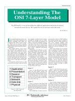
Traditionally, layer diagrams are
drawn with Layer 1 at the bottom and
Layer 7 at the top. The remainder of
this article describes each layer, start-
ing from the bottom, and explains
some of the devices and protocols you
might expect to find in your data cen-
tre operating at this layer.
Layer 1
Layer 1 is the Physical Layer and,
under the OSI Model, defines the
physical and electrical characteristics
of the network. The NIC cards in your
PC and the interfaces on your routers
all run at this level since, eventually,
they have to pass strings of ones and
zeros down the wire.
Layer 2
Layer 2 is known as the Data Link
Layer. It defines the access strategy for
sharing the physical medium, includ-
ing data link and media access issues.
Protocols such as PPP, SLIP and HDLC
live here.
On an Ethernet, of course, access is
governed by a device’s MAC address,
the six-byte number that is unique to
each NIC. Devices which depend on
this level include bridges and
switches, which learn which segment’s
devices are on by learning the MAC
addresses of devices attached to vari-
ous ports.
This is how bridges are eventually
able to segment off a large network,
only forwarding packets between
ports if two devices on separate seg-
ments need to communicate. Switches
quickly learn a topology map of the
network, and can thus switch packets
between communicating devices very
quickly. It is for this reason that mi-
grating a device between different
switch ports can cause the device to
lose network connectivity for a while,
until the switch, or bridge, re-ARPs
(see box on ARP).
Layer 3
Layer 3 is the Network Layer, pro-
viding a means for communicating
open systems to establish, maintain
and terminate network connections.
The IP protocol lives at this layer, and
so do some routing protocols. All the
routers in your network are operating
at this layer.
Layer 4
Layer 4 is the Transport Layer, and
is where TCP lives. The standard says
that “The Transport Layer relieves the
Session Layer [see Layer 5] of the bur-
den of ensuring data reliability and
integrity”. It is for this reason that peo-
ple are becoming very excited about
the new Layer 4 switching technology.
Issue 120 (July 2000) Page 13 File: T04124.1
The OSI model is a way of describing how different applications and protocols interact
on network-aware devices. We explain the role of each layer and of the stack.
By Neil Briscoe
Understanding The
OSI 7-Layer Model
Figure 1 - The 7 layers of
the OSI model.
PC Network Advisor
www.itp-journals.com
Tutorial:Overview
Before these devices became available,
only software operated at this layer.
Hopefully, you will now also un-
derstand why TCP/IP is uttered in one
breath. TCP over IP, since Layer 4 is
above (over) Layer 3. It is at this layer
that, should a packet fail to arrive (per-
haps due to misrouting, or because it
was dropped by a busy router), it will
be re-transmitted, when the sending
party fails to receive an acknow-
ledgement from the device with which
it is communicating.
The more powerful routing proto-
cols also operate here. OSPF and BGP,
for example, are implemented as pro-
tocols directly over IP.
Layer 5
Layer 5 is the Session Layer. It pro-
vides for two communicating presen-
tation entities to exchange data with
each other. The Session Layer is very
important in the E-commerce field
since, once a user starts buying items
and filling their “shopping basket” on
a Web server, it is very important that
they are not load-balanced across dif-
ferent servers in a server pool.
This is why, clever as Layer 4
switching is, these devices still operate
software to look further up the layer
model. They are required to under-
stand when a session is taking place,
and not to interfere with it.
Layer 6
Layer 6 is the Presentation Layer.
This is where application data is either
packed or unpacked, ready for use by
the running application. Protocol con-
versions, encryption/decryption and
graphics expansion all takes place
here.
Layer 7
Finally, Layer 7 is the Application
Layer. This is where you find your
end-user and end-application proto-
cols, such as telnet, ftp, and mail (pop3
and smtp).
The Stack
Our imaginary listener, eavesdrop-
ping on the conversations of network
engineers, would hear them refer to IP
stacks quite frequently. They are called
stacks because, in order to get a packet
from an application running on device
A to an application running on device
B, the packets have to descend and
then re-ascend the layers (the stack).
Consider the following example.
An application forms a packet of data
to be sent; this takes place at Layer 7.
As the packet descends the stack, it is
wrapped in headers and trailers, as
required by the various protocols, un-
til, having reached Layer 1, it is trans-
mitted as a frame across the medium
in use. Upon reaching device B, it re-
ascends the stack, as the device strips
off the appropriate headers and trail-
ers, delivering just the application data
to the application.
The OSI tried to keep to as few lay-
ers as possible for the sake of simplic-
ity. The fact that the 7-Layer model is
universally used to describe where a
device or protocol sits in the scheme of
things shows that the designers did an
excellent job of achieving their aims.
File: T04124.2 Issue 120 (July 2000) Page 14
The Author
Neil Briscoe is a networking con-
sultant and Cisco guru and can be
contacted as neil.briscoe@itp-
journals.com.
PCNA
Copyright ITP, 2000
Address Resolution Protocol (ARP)
Bridges, switches, and most network devices keep a table mapping IP
addresses to Media Access addresses. Moving a device between ports
invalidates these tables, and hence the device’s view of the world.
Fortunately, the devices age their table entries, typically clearing them out
five minutes after the last time a packet was seen from a particular entity.
This is sometimes called re-ARPing. Most bridges and switches provide
management functions to allow you to clear the ARP entry manually, should
you have needed to move a device due to a failed port.
Further Reading
www.whatis.com
This impressive site hosts infor-
mation on a wide range of sub-
jects, a lot of it network-related,
including a more in-depth discus-
sion of the OSI. Visit the site, click
on the letter O at the top, and then
scroll down the list of topics until
you find OSI.
“They are called stacks because, in
order to get a packet from an application
running on device A to an application
running on device B, the packets
have to descend and then re-ascend
thelayers(thestack).”
PC Network Advisor
www.itp-journals.com
Tutorial:Overview
PC Network Advisor
www.pcnetworkadvisor.com
Additional Resources
•
TCP/IP Tutorial
•
Understanding IPv
6
•
Understanding NAT
•
Understanding Frame Relay
•
Understanding DHCP
•
Virtual Private Networking Explained
All these articles are available free online now at
www.pcnetworkadvisor.com
PCNA
Copyright ITP, 2002
Recent Reviews from
Tech Support Alert
Reviews of the Best Windows Backup Software
In this detailed comparative review, we checked out eighteen backup software
utilities designed for home or SOHO use. Many of the products reviewed
were disappointing. However 6 products passed our tests with flying colors
and 2 of these were so impressive, they were awarded our “Editor’s Choice.”
Suppliers of Cheap Inkjet Printer Cartridges Reviewed and Rated
With hundreds of companies all claiming to have the “cheapest and best inkjet
printer cartridges
,” our editors decided to put their claims to the test. Not
unexpectedly, many suppliers flunked but we did manage to come up with a
number of web sites that sell good quality inkjet printer cartridges at heavily
discounted prices.
The Best Anti Trojan Software
Our editors took a close look at the 6 leading anti-trojan/trojan remover
software utilities. Unfortunately, they found only 2 products that were effective
in their ability to detect and remove dangerous modern polymorphic and
process injecting trojans.
The 46 Best Ever Freeware Utilities
This is our Editor, Ian “Gizmo” Richards, personal selection of the best
freeware utilities. He’s hunted down some real gems, many of which perform
better than expensive commercial products.
Tech Support Alert