Tài liệu The z-CL6 Six-Channel Mastering Dynamics Processor doc
Bạn đang xem bản rút gọn của tài liệu. Xem và tải ngay bản đầy đủ của tài liệu tại đây (150.5 KB, 11 trang )
z-CL6 manual © 2000, Z-Systems Audio Engineering
The z-CL6 Six-Channel
Mastering Dynamics Processor
Controlling Attack and Release Times.................................................................................................................. 3
Controlling Threshold and Compression Ratio................................................................................................... 4
Controlling Hipass Filters and Make-up Gain..................................................................................................... 4
Saving and Loading Presets ................................................................................................................................... 5
MIDI Automation.................................................................................................................................................. 6
Adjusting Wordwidth............................................................................................................................................ 7
Controlling Compressor Linking.......................................................................................................................... 8
Specifications........................................................................................................................................................ 11
Figure 1 - z-CL6 front panel controls ................................................................................................................... 2
Figure 2 - attack/release screen.............................................................................................................................. 3
Figure 3 - threshold/ratio screen........................................................................................................................... 4
Figure 4 - hipass/make-up gain screen ................................................................................................................. 4
Figure 5 - preset mode........................................................................................................................................... 5
Figure 6 - confirmation of preset save .................................................................................................................. 6
Figure 7 - indication that preset has not been saved............................................................................................ 6
Figure 8 – MIDI control screen............................................................................................................................. 7
Figure 9 - wordwidth/sample rate mode .............................................................................................................. 7
Figure 10 - compressor linking screen.................................................................................................................. 8
Figure 11 - z-CL6 block schematic...................................................................................................................... 10
z-CL6 manual
2
LRS:
SUB:
LRF:
CEN:
thr -12.0
thr -12.0
-8 0
0
0
0
-8
-8
-8
rat 1.4:1
rat 1.1:1
thr -11.0
thr -11.0
rat 3.0:1
rat LIMIT
(G) threshold/ratio screen select button
(H) cross-linking screen select button
(I) attack/release screen select button
(B) channel select knob
(D) parameter #1 control knob
(F) parameter #2 control knob
(K) presets/wordwidth screen select button
(C) parameter #1 display (E) parameter #2 display
(M) gain reduction meter
(A) channel indicator
(L) channel bypass buttons
(J) hipass/make-up gain screen select button
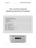
Figure 1 - z-CL6 front panel controls
Using the z-CL6 is very simple once you understand its display and control methodology.
Because there are so many channels and so many parameters for each channel, only a few things
can be displayed at a time. We have chosen to display the same parameters for all channels rather
than all of the parameters for a selected channel; this is the basis for our display/control model.
To begin, the z-CL6 partitions the channels into four groups:
•
LRF – left and right front channels
•
LRS – left and right surround channels
•
CEN – the center channel
•
SUB – the subwoofer channel
Referring to Figure 1, there are four parameter control screens, each selected by one of the screen-
select buttons (G, H, I, and J). These screen-select buttons each invoke a different mode in which
the parameters associated with that mode can be controlled by the parameter #1 and parameter #2
control knobs (D and F). These four modes are:
•
Attack/release mode (invoked by button I)
•
Threshold/ratio mode (invoked by button G)
•
Hipass/make-up gain mode (invoked by button J)
•
Compressor cross-linking mode (invoked by button H)
The parameters associated with these modes are displayed in the parameter #1 display (C) and the
parameter #2 display (E). Within any of the modes, use the channel select knob (B) to choose
which channel group is affected by the parameter control knobs. As you turn the channel select
knob, the channel indicator (A) will point to the corresponding channel.
There is a gain reduction meter (M) which is visible from any of the four mode screens. The gain
reduction meter gives a simultaneous visual display of the amount of gain reduction being
performed on all four of the channel groups. The meter continues to function while you are
changing the values of the parameters, which gives useful visual feedback about your parameter
choices.
z-CL6 manual
3
Each of the channel groups is endowed with a channel bypass button (L). When this button is
pressed, the corresponding compressor is disengaged and there is a direct signal path from input
to output for that channel group; output is bit-for-bit identical to output. When the bypass
button is pushed, the gain-reduction meter for that particular channel vanishes and is replaced
with a bypass indicator. While a channel is bypassed, its parameters can still be adjusted. These
new parameters will be in effect when the channel is taken out of bypass.
Finally, there is a button (K) for invoking a system mode where you can control the wordwidths
of the different channel groups and you can save and load presets.
Controlling Attack and Release Times
LRS:
SUB:
LRF:
CEN:
att 0.05
att 10.0
att 100
att 0.10
-8 0
0
0
0
-8
-8
-8
rel 5.0
rel 10.0
rel 50.0
rel 100
Figure 2 - attack/release screen
Press the attack/release screen select button. The display will appear as in Figure 2. Use the
channel select knob to move the arrow to the desired channel. The parameter #1 knob controls
the attack time and the parameter #2 knob controls the release time. Both the attack time and
the release time are calibrated in milliseconds. The gain reduction meters will continue to
function when the z-CL6 is in attack/release mode, as will the individual channel bypass buttons.
Attack times range from instant to 950 milliseconds. Release times range from instant to 950
milliseconds. A typical rule of thumb is to set the release time to ten times the attack time. Notice
that the z-CL6 has more attack time choices than release time choices, with a higher density of
values below 10 milliseconds.
z-CL6 manual
4
Controlling Threshold and Compression Ratio
LRS:
SUB:
LRF:
CEN:
thr -12.0
thr -14.0
thr -12.0
thr -18.0
-8 0
0
0
0
-8
-8
-8
rat LIMIT
rat 1.1:1
rat 3.0:1
rat 2.0:1
Figure 3 - threshold/ratio screen
Press the threshold/ratio screen select button. The display will appear as in Figure 3. Use the
channel select knob to move the arrow to the desired channel. The parameter #1 knob controls
the threshold and the parameter #2 knob controls the compression ratio. The threshold is
calibrated in decibels relative to full-scale digital (dBFS) and the compression ratio is to be
determined as the number of decibels the input level must rise above the threshold in order to
produce a one-decibel increase in output level. The gain reduction meters will continue to
function when the z-CL6 is in threshold/ratio mode, as will the individual channel bypass buttons.
The threshold ranges from 0.0 dB to -95 dB. The ratio can be made to vary from 1.1:1 to 8.0:1.
Turning the ratio knob one click past 8.0:1 turns the compressor for that particular channel into a
limiter, with a ratio of 100:1.
Controlling Hipass Filters and Make-up Gain
LRS:
SUB:
LRF:
CEN:
hp 100 Hz
hp 100 Hz
hp 10 Hz
hp 100 Hz
-8 0
0
0
0
-8
-8
-8
mkg +1.00
mkg +0.00
mkg +0.60
mkg +0.00
Figure 4 - hipass/make-up gain screen
Press the hipass/make-up button. The display will appear as in Figure 4. Use the channel select
knob to move the arrow to the desired channel. The parameter #1 knob controls the corner
frequency of the hipass filter (explained below) and the parameter #2 knob controls the
compressor make-up gain. The make-up gain is calibrated in decibels relative to full-scale digital
(dBFS). The gain reduction meters will continue to function when the z-CL6 is in hipass/make-
up gain threshold/ratio mode, as will the individual channel bypass buttons.
z-CL6 manual
5
The purpose and function of the hipass filters require a bit of explanation. In essence, a
compressor consists of two blocks: a level detection block and a gain control block. The level
detection block senses the level of the input signal and compares it to the user-determined
threshold. When the input level exceeds the threshold, the detection block tells the gain control
block to decrease the output level by the amount specified by the compression ratio. We have
provided a hipass filter that goes before the level control block. This allows you to remove a
desired amount of the low-frequency energy from the input signal so that the low frequencies
don’t trigger the compressor. This may prove to be useful for previewing different bass
management modes for Dolby and DTS surround mastering.
The corner frequency parameter specifies the – 3 dB point for the hipass filter. Below the corner
frequency, the filter has a slope of 12 dB per octave. The corner frequency can be varied from 10
Hz to 990 Hz. The 10 Hz setting is useful simply for blocking DC level from the level detector.
Do not be alarmed by the presence of these hipass filters; remember – they are not in the audio
path, but rather in the level detection path.
The make-up gain function serves two purposes. The first is to allow you to increase the overall
signal level, post-compression. The second is as a digital volume control for controlling relative
levels between the various surround groups. The make-up gain has a range from –95 dB to +12
dB referenced relative to full-scale digital (dBFS).
Saving and Loading Presets
The entire state of the z-CL6 can be saved and recalled. Press the presets button once. This will
bring the z-CL6 to the state shown in Figure 8. To save a preset, use the middle knob (as
prompted by the display) to choose a preset number then press the button beneath the SAVE
indication. This will then bring the z-CL6 to the state shown in Figure 9, which confirms that the
SAVE operation took place.
LOAD
preset #21
(L knob) (R knob)
MIDI #12
SAVE READDUMP
Figure 5 - preset mode