Tài liệu Dynamic Reconfiguration of Indoor Combination Networks Through the Use of Patch Panels pdf
Bạn đang xem bản rút gọn của tài liệu. Xem và tải ngay bản đầy đủ của tài liệu tại đây (1.68 MB, 4 trang )
Dynamic Reconfiguration
of Indoor Combination Networks Through the Use of Patch Panels
Executive Summary
In terms of flexibility, the traditional combination networks found inside hubs and headends are
quite rigid, making it difficult to change combination ratios. Adding radio-frequency patch panels
to combination networks adds a high degree of flexibility and allows for different levels of
combination without affecting network service.
Issues in Traditional Configuration Networks
Over the past few years, cable operators have encountered an unexpected problem integrating
high-speed data and integrated telephony services.
Initially, high-speed data and integrated telephony services were deployed using a design that
assigned fixed ratios of combination between the number of homes and the controller inputs in
hubs and headends. For example, operators often assigned 1,000 homes to a DOCSIS upstream
input for cable-modem service.
As a result, it’s common to find a first splitting stage just after the optical receivers inside the hubs
in an upstream network. Following the first splitting stage is a series of combination stages that
group the return path of the optical nodes in ratios that vary according to the provided service.
Using high-speed data as an example, these stages could result the grouping of a signal coming
from eight optical nodes into one CMTS upstream input.
This creates a rigid ratio structure with fixed combiners and splitters that condition the service.
A clear example can be seen in the following illustration, where the number of cable-modem users
has grown and the combination networks limits the number of users that can be served by the
network.
APPLICATION NOTE
www.adc.com • +1-952-938-8080 • 1-800-366-3891
Groups of
8
Upstream
Signals
Groups of
8
Upstream
Signals
Groups of
32
Upstream
Signals
Cable Modem
Concentration
Stage
Distribution
Stage
Switch
Opt. Rec.
Opt. Rec.
Opt. Rec.
Opt. Rec.
Opt. Rec.
Opt. Rec.
Switch
Switch
Integrated
Telephony
Concentration
Stage
Conditional
Access and
Monitoring
Concentration
Stage
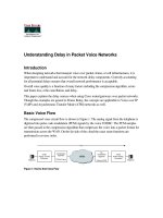
Alternative Through the Use of Radiofrequency Patch Panel
Necessary Situation After Growth of Penetration
In this example, subscriber penetration causes the need for change from Initial Situation to Necessary
Situation. It forces reengineering the network along with adding and removing devices and cabling.
One solution to this dilemma is to create a more flexible combination network. The inclusion of patch
panels provides the needed flexibility, providing for growth without negatively affecting existing cabling
and devices.
The following diagram illustrates how, with the addition of patch panels, an operator can change the
ratio of optical nodes attached per upstream input in the CMTS, resulting in the following advantages:
• As the ratio changes, there is no effect on the fixed cabling as all the fixed cabling is on the rear side
of the patch panels
• Changes can be made without affecting service as it’s only necessary to make the change in the
CMTS input
• New services and nodes can be added without affecting service
• New CMTS or Integrated Telephony cards can be added to the shelves without affecting service
7/05 • 1332621
Dynamic Reconfiguration
Dynamic Reconfiguration
of Indoor Combination Networks Through the Use of Patch Panels
2
www.adc.com • +1-952-938-8080 • 1-800-366-3891
CMTS Input 1
500 Users
Maximum
2000 homes in
4 optical nodes
500 can be served
25% penetration
4:1
CMTS Input 1
500 Users
Maximum
2000 homes in
4 optical nodes
1000 can be served
50% penetration
2:1
CMTS Input 2
500 Users
Maximum
2:1
Initial Situation
Distribution
Stage
Concentration
Stage
Opt. Rec.1
Opt. Rec. N
Flexible with Patch Panels at Different Stages
It’s important to note that while the diagram shows the return path of the network, the same
philosophy should be applied to the downstream path.
7/05 • 1332621
Dynamic Reconfiguration
Dynamic Reconfiguration
of Indoor Combination Networks Through the Use of Patch Panels
3
www.adc.com • +1-952-938-8080 • 1-800-366-3891
4:1 4:1
CMTS
1
CMTS
2
4:1
CMTS
1
4:1 4:1
CMTS
1
CMTS
2
1. Initial Situation
Combination of 4 Nodes
per Upstream Input in the CMTS
2. Temporary Change Without
Affecting Service
to a Combination of 2 Nodes
per Upstream Input in the CMTS
3. Final Situation
Combination of 2 Nodes
per Upstream Input in the CMTS
SJ-2000 Jack
The flexibility described in this example is based on the functionality of SJ-2000 jacks. The use of this
jack allows instantaneous signal rerouting.
Patch panels act as the mechanical support for the jacks. The two rear connectors are bridged as the
jack acts as a loop with the front connectors 75 Ohm-terminated. When a jack is inserted into any of
the front inputs, the corresponding rear connection is rerouted to the front and goes through the
inserted jack. Simultaneously, the unconnected connections are grounded to avoid RF interference.
ADC Telecommunications, Inc., P.O. Box 1101, Minneapolis, Minnesota USA 55440-1101
Specifications published here are current as of the date of publication of this document. Because we are continuously
improving our products, ADC reserves the right to change specifications without prior notice. At any time, you
may verify product specifications by contacting our headquarters office in Minneapolis. ADC Telecommunications,
Inc. views its patent portfolio as an important corporate asset and vigorously enforces its patents. Products or
features contained herein may be covered by one or more U.S. or foreign patents. An Equal Opportunity Employer
101107 9/05 Original © 2005 ADC Telecommunications, Inc. All Rights Reserved
Web Site: www.adc.com
From North America, Call Toll Free: 1-800-366-3891 • Outside of North America: +1-952-938-8080
Fax: +1-952-917-3237 • For a listing of ADC’s global sales office locations, please refer to our web site.
APPLICATION NOTE
Normal Operation
Loop
Patch Operation
(Reconfiguration)
Routing Through the
Front Inserted Jack