Tài liệu Lab 3.1.5 Configuring a Serial Interface pptx
Bạn đang xem bản rút gọn của tài liệu. Xem và tải ngay bản đầy đủ của tài liệu tại đây (93.79 KB, 5 trang )
1 - 5 CCNA 2: Routers and Routing Basics v 3.0 - Lab 3.1.5 Copyright 2003, Cisco Systems, Inc.
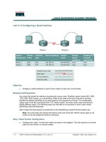
Lab 3.1.5 Configuring a Serial Interface
Objective
• Configure a serial interface on each of two routers so they can communicate.
Background/Preparation
Any router that meets the interface requirements may be used. Possible routers include 800, 1600,
1700, 2500 and 2600 routers, or a combination. Refer to the chart at the end of the lab to correctly
identify the interface identifiers to be used based on the equipment in the lab. The configuration
output used in this lab is produced from 1721 series routers. Any other router used may produce
slightly different output. The following steps are intended to be executed on each router unless
specifically instructed otherwise.
Start a HyperTerminal session as performed in the Establishing a HyperTerminal session lab.
Note: Go to the erase and reload instructions at the end of this lab. Perform those steps on all
routers in this lab assignment before continuing.
Step 1 Basic Router Configuration
a. Configure the router. Connect the routers as shown in the diagram. This lab requires a null serial
cable and two rollover or console cables.
Step 2 Configure the name and passwords for Router 1
Router
Designation
Router
Name
Interface
type
Serial 0
Address
Subnet mask
Enable secret
password
Enable/VTY/Consol
e passwords
Router 1
GAD
DCE 192.168.15.1 255.255.255.0 class cisco
Router 2
BHM
DTE 192.168.15.2 255.255.255.0 class cisco
2 - 5 CCNA 2: Routers and Routing Basics v 3.0 - Lab 3.1.5 Copyright 2003, Cisco Systems, Inc.
a. On Router 1, enter the global configuration mode and configure the hostname as shown in the
chart.
b. Configure the console, virtual terminal and enable passwords. If there are any problems, refer to
the Configuring router passwords lab.
Step 3 Configure serial interface Serial 0
From the configure terminal mode, configure serial interface Serial 0 on Router GAD. Refer to
interface chart.
GAD(config)#interface serial 0
GAD(config-if)#ip address 192.168.15.1 255.255.255.0
GAD(config-if)#clock rate 56000
GAD(config-if)#no shutdown
GAD(config-if)#exit
GAD(config)#exit
Note: Once the interface configuration mode is entered, note the ip address of the interface.
Enter the subnet mask. Enter the clock rate only on the DCE side of the device. The command
no shutdown turns on the interface. Shutdown is when the interface is off.
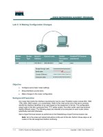
Step 4 Save the running configuration
Save the running configuration to the startup configuration at the privileged exec mode:
GAD#copy running-config startup-config
Note: Save the running configuration for the next time that the router is restarted. The router can
be restarted either by a software reload command or a power shutdown. The running
configuration will be lost if the running configuration is not saved. The router uses the startup
configuration when the router is started.
Step 5 Display information about Serial interface 0 on GAD
a. Enter the command show interface serial 0 on GAD. Refer to interface chart.
GAD#show interface serial 0
This will show the details of interface serial 0.
b. List at least following 3 details discovered by issuing this command.
c. Serial0/0 is
___________________
. Line protocol is
___________________
.
d. Internet address is
_____________________.
e. Encapsulation
_________________________
f. To what OSI layer is the “Encapsulation” referring?
_______________________________
g. If the Serial interface was configured, why did the show interface serial 0 say that the interface
is down?
__________________________________________________________________________
Step 6 Configure the name and passwords for Router 2
3 - 5 CCNA 2: Routers and Routing Basics v 3.0 - Lab 3.1.5 Copyright 2003, Cisco Systems, Inc.
a. On the Birmingham router, enter the global configuration mode. Configure hostname, console,
virtual terminal and enable passwords as shown in the previous chart.
Step 7 Configure serial interface Serial 0
From the configure terminal mode, configure serial interface Serial 0 on Router BHM. Refer to
interface chart.
BHM(config)#interface serial 0
BHM(config-if)#ip address 192.168.15.1 255.255.255.0
BHM(config-if)#no shutdown
BHM(config-if)#exit
BHM(config)#exit
Step 8 Save the running configuration
Save the running configuration to the startup configuration at the privileged exec mode:
BHM#copy running-config startup-config
Step 9 Display information about Serial interface 0 on BHM
a. Enter the command show interface serial 0 on BHM. Refer to interface chart.
BHM#show interface serial 0
This will show the details of interface serial 0.
b. List at least following 3 details you discovered from issuing this command.
c. Serial0/0 is
___________________
, line protocol is
___________________
.
d. Internet address is
___________________ .
e. Encapsulation
___________________
f. What is the difference in the Line and Protocol status recorded on GAD earlier? Why?
__________________________________________________________________________
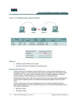
Step 10 Verify that the serial connection is functioning
a. ping the serial interface of the other router.
BHM#ping 192.168.15.1
GAD#ping 192.168.15.2
b. From GAD, ping the BHM router serial interface. Does the ping work?
_________________
c. From BHM, ping the GAD router serial interface. Does the ping work?
_________________
d. If the answer is no for either question, troubleshoot the router configurations to find the error.
Then do the pings again until the answer to both questions is yes.
Upon completion of the previous steps, logoff by typing exit. Turn the router off. Remove and store
the cables and adapter.
4 - 5 CCNA 2: Routers and Routing Basics v 3.0 - Lab 3.1.5 Copyright 2003, Cisco Systems, Inc.
Erasing and reloading the router
Enter into the privileged exec mode by typing enable.
If prompted for a password, enter class. If “class” does not work, ask the instructor for assistance.
Router>enable
At the privileged exec mode enter the command erase startup-config.
Router#erase startup-config
The responding line prompt will be:
Erasing the nvram filesystem will remove all files! Continue?
[confirm]
Press Enter to confirm.
The response should be:
Erase of nvram: complete
Now at the privileged exec mode enter the command reload.
Router(config)#reload
The responding line prompt will be:
System configuration has been modified. Save? [yes/no]:
Type n and then Enter.
The responding line prompt will be:
Proceed with reload? [confirm]
Press Enter to confirm.
In the first line of the response will be:
Reload requested by console.
After the router has reloaded the line prompt will be:
Would you like to enter the initial configuration dialog? [yes/no]:
Type n and then Enter.
The responding line prompt will be:
Press RETURN to get started!
Press Enter.
The router is ready for the assigned lab to be performed.
5 - 5 CCNA 2: Routers and Routing Basics v 3.0 - Lab 3.1.5 Copyright 2003, Cisco Systems, Inc.
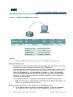
Router Interface Summary
Router
Model
Ethernet
Interface #1
Ethernet
Interface #2
Serial
Interface #1
Serial
Interface #2
Interface
#5
800 (806) Ethernet 0 (E0) Ethernet 1 (E1)
1600 Ethernet 0 (E0) Ethernet 1 (E1) Serial 0 (S0) Serial 1 (S1)
1700 FastEthernet 0 (FA0) FastEthernet 1 (FA1) Serial 0 (S0) Serial 1 (S1)
2500 Ethernet 0 (E0) Ethernet 1 (E1) Serial 0 (S0) Serial 1 (S1)
2600 FastEthernet 0/0
(FA0/0)
FastEthernet 0/1 (FA0/1) Serial 0/0 (S0/0) Serial 0/1
(S0/1)
In order to find out exactly how the router is configured, look at the interfaces. This will identify the type of router
as well as how many interfaces the router has. There is no way to effectively list all of the combinations of
configurations for each router class. What is provided are the identifiers for the possible combinations of interfaces
in the device. This interface chart does not include any other type of interface even though a specific router may
contain one. An example of this might be an ISDN BRI interface. The string in parenthesis is the legal abbreviation
that can be used in IOS command to represent the interface.