Tài liệu CCIE Practice Scenario Labs doc
Bạn đang xem bản rút gọn của tài liệu. Xem và tải ngay bản đầy đủ của tài liệu tại đây (220.19 KB, 7 trang )
CISCO SYSTEMS TECHNICAL READINESS DOCUMENT
CCIE Practice Scenario Labs
Introduction
This document is designed to be a companion to Volume 1,2,3 and 4. The CCIE
certification is a written test and a lab test. This document will help the student further build
upon their technical skills and configuration skills. The document contains practice CCIE
scenario labs.
Background
These scenarios have been compiled from various sources including current partner CCIEs.
These are not the only scenarios you will be tested with on the CCIE lab exam. They are
designed to give you a flavor for the lab exam. Students are encouraged to use these
scenarios to assist them in devising other scenarios with different physical topologies using
multiprotocol scenarios.
REMEMBER: YOU CAN BE TESTED ON ANY AND ALL TECHNOLGIES ON
THE CCIE LAB EXAM
Prerequisites
The student must also have taken and past the CCIE written test.
CISCO SYSTEMS TECHNICAL READINESS DOCUMENT
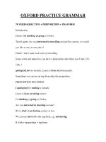
CCIE Practice Lab Scenario 2
W here there is no FD D I available T oken R ing m ay be used
Fram
e
Rela
y
S0
S1
E0
E0
E 0/0
E 0/2
E 0/1
FDDI
Dual
Ring
R2
R3
R1
E1
S 2/0
O SPF B ackbone
A
A rea 1
A rea 2
A rea 3
EIGRP
IG R P
R4
The following lab exercises are based on the above topology
CISCO SYSTEMS TECHNICAL READINESS DOCUMENT
Lab 1 Communications Server Setup / Network Connections (30 minutes)
1. The Communications Server is cabled as shown on the previous diagram.
2. Communication Server port 2 is connected to a 7000 (R2).
3. Communication Server port 3 is connected to a 4500 (R3).
4. Communication Server port 4 is connected to a 4700 (R1)
5. Configure the Communications Server so that when you type the name of a
router on the Server you are connected to the console port of that
respective router.
Lab 2 IP Routing Configuration (30 minutes)
The objective of this lab is to configure OSPF/IGRP/EIGRP/BGP in
different parts of the network and to redistribute routing information. In the
working setup all routers should see every route and should be able to ping any
interface in the network. Do NOT configure static routes to accomplish this.
Topology and Basic IP Setup
You will be using the CLASS B network 172.17.0.0 with the 3’rd octet
set to 59. Thus all your addresses should look like 172.17.59.X
2a Configure R3 as a frame relay switch (Time 30 minutes)
1. DLCI 100 goes to R1.
2. DLCI 101 goes to R2.
2b
Configure IP across the Frame Relay network (Time 30 minutes)
1. Use a 28 bit subnet mask.
2. Confirm connectivity across the Frame Relay network by pinging from R2 to R1.
CISCO SYSTEMS TECHNICAL READINESS DOCUMENT
2c
Configure IP across the remaining interfaces (Time 45 minutes)
1. Configure R2 Ethernet 0/0 to IP address 171.68.62.93 with a 26 bit subnet mask.
2. Subnet Ethernet 0/1 on R2 such that it has 6 host addresses.
3. Subnet the Ethernet that connects R2 and R3 using a 30 bit subnet mask.
4. Subnet R3 ‘s Ethernet 1 such that it has 14 host addresses.
5. Subnet the R1’s FDDI ring such that it has 2 hosts.
6. Verify that you have basic IP setup by pinging the local interfaces that you have just
configured.
2d: Configure OSPF on your network as per Diagram 3 (Time 45 minutes)
1.
Configure OSPF on R2, R3, and R1. Refer to Diagram 3 for area designations.
2. Ensure that R2 can ping R1’s FDDI interface and R3’s Ethernet 1 interface. Also ensure
that R1 can ping R3’s Ethernet 1 interface.
Lab 2e: IGRP Configuration and Redistribution (time 45 minutes)
1.
Configure IGRP on R4’s Ethernet 0 and R2’s Ethernet 0/0.
2.
Make sure that these are the ONLY interfaces that are advertising IGRP.
3.
Redistribute OSPF into IGRP on R2.
4. Verify that R4 can ping all interfaces in the OSPF domain.
Lab 2f: EIGRP Configuration and Redistribution (time 30 minutes)
1.
Configure EIGRP on R2’s Ethernet 0/1.
2.
Make sure that this is the ONLY interface that is advertising EIGRP.
3.
Redistribute OSPF into EIGRP and EIGRP into OSPF.
4. Redistribute the connected interface Ethernet 0/1 into OSPF and IGRP.
5.
Verify that R1 and R4 can ping R2’s Ethernet 0/1.
CISCO SYSTEMS TECHNICAL READINESS DOCUMENT
Lab 2g: BGP Configuration(30 minutes)
1. Configure BGP on R3 and R2:
2. R3 and R2 should have different autonomous system numbers.
3.
Configure 3 loopback interface on R3 using the network addresses
150.100.0.0,
160.100.0.0, and 170.100.0.0.
4.
Configure BGP between R3 and R2 such that R2 sees all three loopbacks configured on
R3.
5.
A “show ip bgp” on R2 should show the three routes advertised by R3.
Lab 2h: BGP Route Filter (15 minutes)
1.
Configure a filter on R2 such that the only route now seen on R2 is 150.100.0.0.
Lab 3: IP FIREWALL (30 minutes)
Configure an inbound access-list on R3’s Ethernet 0 interface
that satisfies the following criterion:
1. Telnet sessions are permitted only if originated from R4’s ethernet interface subnet.
2. FTP sessions are permitted only if established from R3’s Ethernet 1 subnet.
3. TFTP is permitted both ways allowed.
4. SMTP is not allowed.
5. WWW is not allowed.
6. PING is permitted from everywhere.
7. Confirm access to the network after applying the access list. Ping R3’s Ethernet 1 from
R1. Also show a telnet to R3 from R2 fails.
Lab 4 Appletalk Routing Configuration (45 minutes)
1.
Configure all ports for appletalk. Use different cable ranges and zones on each interface.
2.
Configure EIGRP for appletalk across the frame-relay network.
4a.
Appletalk filter (45 minutes)
1.
Configure a filter on R2 such that R3 only sees routes and zones from R4.