Tài liệu Tài liệu Diezel 1410 P6 pdf
Bạn đang xem bản rút gọn của tài liệu. Xem và tải ngay bản đầy đủ của tài liệu tại đây (313.98 KB, 10 trang )
6
INTAKE AND EXHAUST SYSTEMS
A. GENERAL
6A1. Intake systems. All of our
modern submarine diesel engines are of
the 2-stroke cycle type. The purpose of
the intake systems in these engines is to
force out the exhaust gases of
combustion as effectively as possible
and to recharge the cylinder with fresh
air in order to support combustion for
the next succeeding cycle. The supply
of air must be in excess of that required
to just support combustion since the
fuel is thoroughly mixed with only part
of the air compressed within the
cylinder. The ratio of air to fuel in most
diesel engines is approximately 20 to 1
at full load.
6A2. Scavenging. The term scavenging
is used to describe the process of
ridding the cylinder of burned exhaust
gases during the latter part of the
expansion stroke and the early part of
the compression stroke of the 2-stroke
cycle engine. Scavenging is
accomplished by admitting fresh air
under a pressure of about 1 to 5 psi into
the cylinder while the exhaust valves or
ports are open. This pressure usually is
developed by means of a scavenging air
blower. These blowers are driven from
the engines themselves and generally
are of the lobed rotor type, the rotors
revolving together in closely fitting
housings. The process of scavenging
must be carried out in an extremely
short period of time, depending upon
the speed of the engine. The burned
gases must be blown out of the cylinder
and a fresh charge of air admitted
during the time that the ports or valves
are open. For example, in an engine
making 750 rpm with the exhaust ports
open for 140 degrees of crank angle,
the elapsed time the ports are open each
revolution is only (140/360) x (60/750)
or approximately 1/32 of a second.
The scavenging air must be so directed
as to remove the burned gases from the
remote parts of the cylinder. The
These methods are illustrated in Figures
6-1 to 6-4. In port direct scavenging, the
exhaust ports are on one side of the
cylinder and the scavenging ports on the
other. In port loop scavenging, the
exhaust and scavenging ports are on the
same side of the cylinder. In uniflow port
scavenging, the air enters at ports at the
lower end of the cylinder and passes out
through ports in the upper end of the
cylinder.
In valve uniflow scavenging, air enters
the cylinder through ports in the bottom
and passes out through exhaust valves in
the cylinder head, carrying the burned
exhaust gases with it.
The ports used for the inlet of scavenging
air are usually constructed so as to give
the air a whirling motion or turbulence to
clear out all possible exhaust gases and
fill the entire cylinder with a charge of
fresh air.
In scavenging air systems, it is possible
to supercharge the cylinder during the air
intake. This is done by closing the
exhaust ports or valves slightly ahead of
the inlet port closure. This allows the air
pressure in the cylinder to build up to
scavenging air pressure, increasing the
amount of air, the air-fuel ratio, and the
combustion efficiency. If the amount of
fuel injected is increased to give the same
air-fuel ratio as before supercharging, the
effect of supercharging is to give more
power output to the cylinder. In the
present submarine type engines, the F-M
engine is supercharged, but the GM
engine is not.
6A3. Intake system components. The
intake systems consist of the following
parts:
a. Air intake silencers and strainers.
Intake air for submarine engines is drawn
from the engine room compartments by
the scavenging air blower through air
methods used may be classified as
follows: port scavenging (direct, loop,
and uniflow), and valve scavenging
(uniflow ).
silencers and strainers. If some type of air
silencer were not used, the noise of the
intake air would be almost unbearable
because of its high-pitched whistling
sound. Strainers are installed to remove
any dirt or other foreign matter that
would otherwise enter the scavenging
blower or engine and cause damage.
119
Figure 6-1. Port direct scavenging.
Figure 6-2. Port loop scavenging.
Figure 6-3. Valve uniflow scavenging.
Figure 6-4. Cross section of F-M
cylinder with uniflow port scavenging.
120
b. Scavenging air blower. The
scavenging air blower furnishes air
under pressure to the intake headers
and receivers and eventually to the
cylinder inlet ports.
c. Air intake headers, receivers, and
necessary piping. The air headers and
the reciprocating motion of the pistons.
The exhaust headers or belts conduct the
exhaust gases from the exhaust valves or
ports to the atmosphere through an
inboard and an outboard exhaust valve
and muffler. The exhaust manifold and
exhaust elbows (if used) are usually
receivers carry the air from the
scavenging air blowers to the inlet ports
of the cylinders. In most installations,
scavenging air headers and receivers
are built into the cylinder block. Drains
are placed in the scavenging air headers
to drain off any liquids that may have
accumulated. Spring-loaded covers are
also furnished in the scavenging air
header to allow the venting of excess
pressure in case of emergency.
d. Intake air ports. The intake air ports
are in the cylinder liner and permit the
scavenging air to pass from the
scavenging air receivers into the
cylinder when the ports are open. The
ports are usually tangentially
constructed so as to give the air a
whirling motion as it enters the
cylinders. They are usually opened and
closed by the reciprocating motion of
the piston.
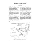
6A4. Exhaust systems. The purpose of
the exhaust system is to convey the
burned exhaust gases of combustion
from the cylinders to the atmosphere as
silently as possible. The system
includes exhaust valves and ports,
headers and pipes, main inboard and
outboard exhaust valves, and engine
mufflers.
The exhaust valves or ports, as the case
may be, are properly timed so as to
permit the gases of combustion to
escape from the cylinder at the correct
point of the cycle. In the GM engine,
this is accomplished by means of
exhaust valves; in the F-M engine, by
means of exhaust ports. Due to the heat
that must pass through these exhaust
valves or ports, they must be made of
special material or be thoroughly
cooled to prevent distortion and pitting.
Valves are usually made of a high
silicon heat-resistant alloy steel. In
some large engine installations, the
exhaust valves may be water or sodium
cooled. A thermocouple is usually
placed at the exhaust elbow to measure
the exhaust temperature of each
cylinder. When exhaust valves are
used, they are opened and closed by
water jacketed to permit cooling of the
piping and manifolds. The cooling water
normally comes from the engine fresh
water system. Cooling of these parts
keeps down the temperature of the metal,
thus prolonging its life and reducing its
expansion to a minimum. In most
exhaust systems, drains are provided to
allow drainage of any accumulated
liquids from the exhaust belts.
In submarine installations, the gases of
combustion are piped from the exhaust
headers to the outside of the submarine
through an in board and outboard main
engine exhaust valve and muffler. The
inboard exhaust valve is inside the
pressure hull of the submarine and is
hand operated. The outboard exhaust
valve is located outside the pressure hull
and is operated either by hand or by
hydraulic power, the controls for the
valve being at the throttleman's station at
the engine. Both inboard and outboard
exhaust valves are water cooled, the
former usually by water from the engine
fresh water system, the latter by water
from the engine salt water system.
Mufflers are placed in the exhaust
system. This is necessary, because in a 2-
stroke cycle engine the uncovering of the
exhaust ports releases a pressure of 20 to
40 psi in the exhaust system and this
produces a noise that can be heard for
miles if not muffled by some form of
silencer. These mufflers are usually of
cast or sheet iron construction with a
system of baffles that break up the noise
without producing back pressure. There
are two general types of mufflers in use,
the wet type and the dry type. In both
types, circulating water is used to reduce
the temperature of the exhaust gases as
much as possible. The difference
between the two is that in the dry type
the exhaust gases do not come in contact
with the cooling water, whereas in the
wet type the gases are expanded in the
muffler in the presence of a water spray.
The exhaust gases in passing through the
water spray are cooled, condensed,
decreased in volume, and
means of rocker arm and camshaft
assemblies. The exhaust ports, if used,
are opened and closed by
121
Figure 6-5. Typical exhaust system piping.
122
effectively silenced. Under normal
operation, the smoke is also eliminated.
Submarine installations use the wet
type of muffler. From the
muffler, the exhaust gases are passed out
into the atmosphere through a section of
piping known as the tail pipe.
B. GENERAL MOTORS INTAKE AND EXHAUST SYSTEM
6B1. General description. The
General Motors engine employs the
uniflow valve method of scavenging.
The blower, mounted at the forward
end of the engine crankcase and driven
by the engine, takes air from the
atmosphere through an attached
silencer and forces it under pressure
into the air box. The air box consists of
the frame space in the engine included
between the two legs of the V-
construction and the open space
between the upper and lower deckplates
of each bank. The air from the air box
goes through the cylinder inlet ports
The exhaust gases are released from the
cylinder when the exhaust valves are
opened by action of the camshaft and
rocker arm assembly. The exhaust valves
are opened ahead of the inlet ports to
allow the pressure of the exhaust gases to
be partially released before the low-
pressure scavenging air is admitted to the
cylinder. The exhaust gases pass through
the exhaust valves into the water-cooled
cylinder head and thence into the exhaust
elbow connecting each cylinder head
with the main exhaust manifold. This
manifold extends longitudinally along the
top centerline of the engine with elbow
whenever the individual pistons
uncover the ports at the end of the
expansion or power stroke. This
scavenging air forces out the exhaust
gases and charges the cylinder with
fresh air.
connections into each cylinder head.
Thermocouples for measuring the
temperature of the exhaust gases for each
cylinder are located in each exhaust
elbow. Both exhaust elbows and exhaust
Figure 6-6. GM cylinder intake and exhaust.
123
manifold are water jacketed for cooling
purposes. From the main exhaust
manifold, the gases pass into a vertical
pipe which leads to the inboard exhaust
valve. From this valve, the gases pass
outside the pressure hull, through
exhaust piping which leads to the
hydraulically operated main engine
outboard exhaust valve, and thence to
the atmosphere by way of the muffler
and tail pipe. The inboard exhaust valve
is cooled by water from the engine
fresh water system, while the outboard
valve is cooled by the engine salt water
system.
Drains are provided in the piping
between the inboard and outboard
exhaust valves so that any salt water
that may have leaked past the outboard
exhaust valve can be drained into the
engine room bilges. On a submarine it
is extremely important that this space
be drained before starting an engine
after surfacing from submerged
operations, otherwise the engine may
be flooded.
6B2. Scavenging air blower. The
Figure 6-7. Cutaway of blower assembly,
GM.