Tài liệu Tài liệu Diezel 1410 P5 pdf
Bạn đang xem bản rút gọn của tài liệu. Xem và tải ngay bản đầy đủ của tài liệu tại đây (790.3 KB, 30 trang )
5
DIESEL ENGINE FUEL SYSTEMS
A. DIESEL FUELS
5A1. General. Normally, diesel fuel
oils for use in the Submarine Service
are purchased by the Bureau of
Supplies and Accounts. At the time of
delivery, the diesel fuel oils are
inspected to make sure that they meet
the specifications set up by the Bureau
of Ships. However, emergencies
occasionally arise both in the supply
and in the handling of diesel fuels that
make it imperative for operating
engineering personnel to have at least a
fundamental knowledge of the
requirements for diesel fuel oil.
5A2. Cleanliness. One of the most
important properties necessary in a
diesel fuel oil is cleanliness. Impurities
are the prime sources of fuel pump and
injection system trouble. Foreign
substances such as sediment and water
cause wear, gumming, corrosion, and
rust in the fuel system. Diesel fuel oil
should be delivered clean from the
refinery. However, the transfer and
handling of the oil increase the chance
of its picking up impurities. The
necessity for periodic inspection,
cleaning, and care of fuel oil handling
and filtering equipment is emphasized
under the subject of maintenance for
each system.
5A3. Chemistry of diesel fuel oil.
Diesel fuel oils are derived from
petroleum, more generally known as
crude oil. All crude oils are composed
of compounds of carbon and hydrogen
known as hydrocarbons. The structure
of the oil is made up of tiny particles
called molecules. In crude oil, a
molecule consists of a certain number
of atoms of carbon and a certain
number of atoms of hydrogen. The ratio
between carbon and hydrogen atoms in
a molecule determines the nature of the
crude oil.
Crude oil is separated into various
products by a process known as
stopped at any point, leaving a residue of
a heavier viscous liquid. This residue
may be cracked in cracking stills by the
application of heat and pressure in the
presence of a catalyst. This cracking
process may be controlled so as to get
products of almost any given type of
hydrocarbon molecular structure. The
products mostly desired are those that
can be used as gasoline and fuel oil
blends.
Fuel oils that meet the specifications for
high-speed diesel engine operation are of
two types, distillate and blended. The
distillate type is obtained by the direct
distillation of crude oil only. Blended
type is obtained by blending the distillate
with the residual products from the
cracking stills. As a general rule,
distillate fuel oil is superior to blended
fuel oil for high-speed diesel operation
because it possesses better ignition
quality, has a lower carbon content, and
contains fewer impurities.
American crude oils are classified into
three types: paraffin base, asphalt base,
and mixed base. These three
classifications depend upon whether
paraffin waxes, asphalt, or both remain
after all the removable hydrocarbons
have been distilled from the petroleum.
5A4. Differences in internal
combustion fuels. The two principal
types of internal combustion fuels are
gasoline and diesel fuel oil. Both types
are hydrocarbons, but the hydrocarbons
differ radically in their chemical
composition.
Gasoline is a fuel adapted to spark
ignition, while diesel fuel oil is adapted
to compression ignition. In spark
ignition, the fuel is mixed with
combustion air before the compression
stroke. In compression ignition, the fuel
is injected into the combustion air near
the end of the compression stroke. Thus a
fractional distillation. In general, each
product is obtained at its particular
boiling point in the distillation process.
The relative order of products obtained,
with their distillation temperature is:
Gasoline-100 degrees to 430
degrees F
Kerosene-300 degrees to 500
degrees F
Fuel oil-400 degrees to 700
degrees F
Lubrication oil-650 degrees F
The fractional distillation process may
be
spark-ignition fuel must have a certain
amount of resistance to spontaneous
ignition from compression heat. The
opposite holds true for diesel fuel oils.
Entirely different ignition properties are
required of the two fuels.
5A5. Properties of diesel fuel oils. The
following are the chief properties
required of diesel fuel oils. With the
definition of each
91
property is an explanation of its
application to engine operation.
a. The ignition quality of a diesel fuel
oil is the ease or rapidity with which it
will ignite.
A diesel fuel with good ignition quality
will auto-ignite (self-ignite) at a
relatively low temperature. In simple
language the fuel will ignite quickly
and easily under relatively adverse
conditions. Thus, where diesel engines
must be started at low temperatures,
good ignition quality makes starting
easier.
Poor ignition quality will cause an
engine to smoke when operating under
a light load at a low temperature. It will
also often cause the engine to knock
and overheat due to the accumulation
of fuel in the cylinder between the
injection and ignition period. The
sudden ignition of accumulated fuel
causes the knock.
There are two widely accepted methods
of determining the ignition quality of a
diesel fuel oil
1. Cetane number test. In this method a
standard reference fuel is used in a test
cylinder. The most widely used
reference fuel is a mixture of cetane
and alpha-methyl-naphthalene. Cetane
reference fuel that produced the same
standard delay period with the same
compression ratio. For example: if the
reference fuel required 60 percent cetane
and 40 percent alpha-methyl naphthalene
to produce the same standard delay
period at the same compression ratio as
the diesel fuel oil tested, then the cetane
rating of the diesel fuel oil is 60.
NOTE. The cetane rating for gasoline
indicates low ignition quality while
cetane rating for diesel fuel oil indicates
relatively high ignition quality. Cetane
numbers of diesel fuels in use today
range from about 30 for engines least
critical to fuel to over 60 for the highest
ignition quality fuels.
2. Diesel index. This method of
determining ignition quality is obtained
by a simple laboratory test. This test
takes into account the fact that there is a
definite relationship between the physical
and chemical properties of diesel fuel oils
and their ignition quality. The diesel
index number method is based on the
relation between the specific gravity of
the fuel oil and the aniline point, which is
the temperature in degrees Fahrenheit at
which equal quantities of the fuel oil and
aniline (a chemical derived from coal tar)
will dissolve in each other. To obtain the
diesel index number, the gravity of the
fuel oil, in degrees API, is multiplied by
the aniline point and divided by 100. The
has an extremely high ignition quality
(ignites quickly) and is rated for the test
at 100. Alpha methyl-naphthalene has a
very low ignition quality (is difficult to
ignite) and is rated for the test at 0.
The single-cylinder test engine used is
like any diesel engine cylinder, except
that the compression ratio of the
cylinder is adjustable. Other cylinder
conditions, including the delay period,
that is, the interval between injection
and ignition, are held constant. This
delay period is measured by electrical
equipment. The fuel to be tested is used
in the test cylinder and the compression
ratio is adjusted until the standard
length delay period is reached. Fuel
with high ignition quality requires a
low compression ratio. Fuel with low
ignition quality requires a high
compression ratio.
Next the reference fuel is used in the
cylinder. Using the same compression
ratio, various mixtures or proportions
of cetane to alpha-methyl-naphthalene
are used until the standard length delay
period is attained. The cetane number
of the diesel fuel oil tested is then equal
to the percentage of cetane in the
result is the diesel index number of the
fuel.
While the diesel index method is
accepted as a fairly reliable method of
determining the ignition quality, the
cetane number test is considered more
accurate. Hence it is preferable to use the
cetane number test where possible. It
must be remembered, however, that the
diesel index test possesses the advantage
of simplicity and low cost. The normal
range of diesel index is from below 20 to
about 60 for diesel fuels in use.
b. Specific gravity. The specific gravity
of a diesel fuel oil is the ratio of its
weight to the weight of an equal volume
of water, both having the same
temperature of 60 degrees F. The specific
gravity of the majority of diesel fuel oils
ranges from 0.852 to 0.934. As a matter
of convenience and to standardize
reference, the American Petroleum
Institute has established the API gravity
scale calibrated in degrees for diesel fuel
oil
93
gravities. Lighter weight fuel oils have
high numbers (about 20 degrees to 40
degrees) and heavier weight fuel oils
have low numbers (from 10 degrees up
to about 20 degrees).
Diesel fuel oils are generally sold by
volume. Hence the specific gravity of a
fuel oil plays an important part
commercially. Knowing the specific
gravity, temperature, and quantity of a
fuel oil, the volume can easily be
computed from standard tables. The
specific gravity of a diesel fuel oil is
often referred to, but its significance is
frequently overestimated. Efforts have
been made at various times, but with
little success, to establish a definite
relationship between gravity and other
characteristics such as viscosity, boiling
heat value than a pound of the heavy oils,
a gallon of the former is generally lower
in heat value than a gallon of the latter.
The difference, however, in the normal
range of diesel fuels is relatively small.
For example, a 24 degrees API diesel
fuel has approximately 3 percent greater
heating value per gallon than a 34
degrees API fuel. Considering the many
factors related to gravity which may
affect over-all thermal efficiency, the
effect of this difference on fuel economy
is usually negligible.
e. Flash point. The flash point of an oil is
the lowest temperature at which a flash
appears on the oil surface when a test
flame is applied under specified test
conditions. It is a rough indication of the
tendency of the product to vaporize as it
is heated. The flash point is important
point, and ignition quality.
c. Viscosity. The viscosity of a fluid is
the internal resistance of the fluid to
flow. The viscosity of a fuel oil is
determined by the Saybolt Universal
Viscosimeter test. In this test, a
measured quantity of the fuel oil is
allowed to pour by gravity through an
opening of established diameter and
with the fuel oil at an established
temperature, usually 100 degrees F.
The length of time in seconds required
for the given quantity of fuel oil to pass
through the opening determines its
viscosity.
Viscosity is important in diesel fuels
because of its effect on the handling
and pumping of the fuel, and on the
injection of the fuel. Viscosity, together
with the rate of fuel consumption,
determines the size of fuel lines, filters,
and fuel pumps. The efficiency of
filtering is greatly increased in a fuel oil
of lower viscosity. In the injection
system viscosity affects the
characteristics of the fuel spray at the
injection nozzles. It also affects the
amount of leakage past pump plungers
and valve stems, and therefore the
lubrication of the various types of
valves and pumps.
d. Heating value. The heating value of
a diesel fuel oil is its ability to produce
a specific Btu output of heat per unit of
weight or volume. There is a definite
relation between the gravity of a diesel
fuel oil and the Btu content. The
relationship is approximately:
Btu per pound of fuel = 17,680 + 60 x
API gravity.
It is well to remember that although a
pound of the lighter grades of oils has a
higher
primarily with relation to regulations
covering handling and storing of
inflammable liquids. It is of little
importance to diesel fuel oil
performance. Most diesel fuels have a
flash point well above 180 degrees F.
The minimum flash point required by
Navy specifications is 150 degrees F.
f. Pour point. The pour point of a diesel
fuel is the temperature at which the fuel
congeals and will no longer flow freely.
This is usually due to the presence of
paraffin wax, which crystallizes out of
the fuel at low temperatures. Pour point
usually determines the minimum
temperature at which the fuel can be
handled, although in some cases, where
there is considerable agitation preventing
the crystallization of wax, the fuel will
usually flow at temperatures below the
pour point.
g. Carbon residue. The carbon residue of
diesel fuels is usually determined by the
Conradson test, in which the fuel is
burned in a covered dish. The carbon
remaining is weighed and expressed as a
percentage of the fuel. The test provides
a rough indication of the amount of high-
boiling heavy materials in the fuel, and is
particularly useful where, because of
high boiling points, distillation data
cannot be obtained. Carbon residue is
sometimes taken as an indication of the
tendency of the fuel to form carbon in the
combustion chamber and on the injection
nozzles, although there is a little basis for
using the test for this purpose due to the
difference in the method of combustion
used in the test and that actually
encountered in an engine.
94
h. Sulphur content. The sulphur content
of a diesel fuel includes both
noncorrosive and corrosive forms of
sulphur. If the sulphur content is high,
sediment to separate. The percentage by
volume is then determined.
The presence of water and sediment is
the copper strip corrosion test should be
made to determine whether or not the
sulphur is in corrosive form. If sulphur
in corrosive form is present, a sample
of the oil should be sent to the nearest
laboratory facility for a test to
determine the percentage present.
Sulphur in excess of Navy maximum
specifications is likely to damage the
engine. When the fuel is burned, the
sulphur is combined with oxygen to
form sulphur dioxide which may react
with water produced by combustion to
form sulphuric acid and cause
excessive cylinder wear. It will also act
to corrode other internal engine parts.
i. Ash content. The ash content of a
diesel fuel oil is the percent by weight
of the noncombustible material present.
This is determined by burning a
quantity of fuel of known weight and
weighing the ash residue. Ash is an
abrasive material and the presence of
ash above the maximum amount
allowed by Navy specifications will
have an obvious wearing effect on
engine parts.
j. Water and sediment. The percent by
volume of water and precipitable
sediment present in the fuel oil is
determined by diluting a quantity of
fuel oil with an equal quantity of
benzol, which is then centrifuged,
causing water and
generally an indication of contamination
during transit and while handling. Fuel
containing water and sediment causes
corrosion and rapid wear in fuel pumps
and injectors.
5A6. Engine troubles caused by fuel.
As indicated in the discussion of diesel
fuel oil properties, any number of engine
troubles may be caused by unclean or
poor fuel oil. Some of the more common
troubles are:
a. Carbon deposits at injection nozzles
may be due to excess carbon residue or
excessive idling of engine.
b. Excess wear of injection pumps and
nozzles may be due to too low a
viscosity, excess ash content, or
corrosion from water or sulphur content
in the fuel oil.
c. Exhaust smoke may result when a fuel
with too high an auto-ignition
temperature is used. This is particularly
true at light loads when engine
temperatures are low.
d. Combustion knock in a diesel engine is
believed to be due to the rapid burning of
a large charge of fuel accumulated in the
cylinder. This accumulation is the result
of nonignition of fuel when it is first
injected into the cylinder, a condition
usually caused by fuel oil of poor
ignition quality.
B. SHIPS FUEL SYSTEM
5B1. General. The engineering
installation on present fleet type
submarines consists of four main
engines and one auxiliary engine.
These are divided between two engine
rooms, with two main engines in the
forward engine room, and two main
engines and the auxiliary engine in the
after engine room. The function of the
ship's fuel oil system is to supply clean
fuel oil to each engine from the ship's
storage tanks. The system may be
divided into two parts: 1) the tanks and
their arrangement, and 2) the different
piping systems.
exception of the clean fuel oil tanks
which are inside the pressure hull.
The two main piping systems found in
the main fuel-oil system are the fuel oil
filling and transfer line and the fuel oil
compensating water line. These lines
connect to the various tanks and give the
fuel oil system a flexibility which it
otherwise would not have.
5B2. The compensating principle. In
order to understand the operation of a
submarine fuel system, it is important to
know the basic fuel oil compensating
The tanks include normal fuel oil tanks,
fuel ballast tanks, clean fuel oil tanks,
expansion tank, and collecting tank. All
of these tanks are in the spaces between
the inner pressure hull and the outer
hull of the submarine with the
principle. In a submarine, to assist in
maintaining trim it is necessary to have
as little weight change as possible when
fuel is being used m a fuel tank.
Therefore, a compensating system is used
which allows salt water to replace fuel oil
as the fuel oil is taken from a tank. Let us
assume that the weight of fuel
95
used is 7.13 pounds per gallon and the
weight of salt water is 8.56 pounds per
gallon. Therefore, when one gallon of
fuel is used from a fuel tank, instead of
the submarine-becoming light by 7.13
pounds, it becomes heavy by 8.56 -
7.13 or 1.43 pounds. The submarine,
then, becomes heavy as fuel oil is used.
This compensating principle is used in
the normal fuel oil tanks, fuel ballast
tanks, expansion tank, and collecting
tank. These tanks must at all times be
filled with a liquid, either fuel oil, sea
water, or a combination of both. The
compensating principle is not used in
the clean fuel oil tanks.
5B3. Fuel oil tanks. a. Normal fuel
tanks. The normal fuel tanks are used
only for the storage of fuel oil. They are
usually located toward the extremities
of the boat rather than close to
amidships. They vary in size, but
normally have capacities of from
10,000 to 20,000 gallons each. Most
modern submarines have four of these
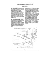
tanks. In a typical installation (Figure
5-1) they are numbered No. 1, No. 2,
No. 6, and No. 7.
b. Fuel ballast tanks. Fuel ballast tanks
are large tanks, amidships, between the
pressure hull and the outer hull, which
may be used either as fuel storage tanks
or as main ballast tanks. They are
connected to the fuel oil system in the
same manner as the normal fuel oil
tanks, but in addition, they have main
vents, main flood valves, and high-
pressure air and low-pressure blower
connections which are necessary when
the tank is in use as a main ballast tank.
When rigged as a main ballast tank, all
connections to the fuel oil system are
c. Collecting tank. The collecting tank is
one side of a section of tank space
between the inner and outer hulls, the
other side being the expansion tank. This
tank has a connection to the fuel oil
filling and transfer line. All of the fuel
used by the engines normally passes
through the collecting tank. A connection
from the top of the collecting tank leads
to the fuel oil meters, fuel oil purifiers,
clean fuel oil tanks, and eventually to the
attached fuel oil pumps on the engines.
This tank has a capacity of about 3,000
gallons, and on submarines is located
outboard of the forward engine room.
The main function of the collecting tank
is to insure that no large amount of water
gets to the purifiers, clean fuel oil tanks
and engine until all the fuel in normal
fuel oil tanks, fuel ballast tanks,
expansion tank, and collecting tank has
been used.
d. Expansion tank. The expansion tank is
alongside and on the opposite side of the
ship from the collecting tank. It is
connected to the fuel oil compensating
water line. It serves two important
functions: first, as a tank to prevent oil
from being blown over the side through
the compensating water line in case of
small air leaks in either the fuel ballast
tanks or the normal fuel oil tanks; and
second, as a tank to which oily bilge
water may be pumped without danger of
leaving a slick. This tank has a capacity
of about 3,000 gallons.
e. Clean fuel oil tanks. The clean fuel oil
tanks, two in number, are used to store
oil prior to its use in the engine and after
it has been purified. These tanks are not
compensated with compensating water.
They have capacities of approximately
secured.
Most fleet type submarines have three
fuel ballast tanks varying in capacity
from about 19,000 to 25,000 gallons.
On a typical installation (Figure 5-1
),
the fuel ballast tanks are numbered No.
3, No. 4, and No. 5. Current practice is
to depart on war patrol with all fuel
ballast tanks filled with fuel oil. Fuel is
used first from No. 4 fuel ballast tank,
and as soon as that tank is empty of fuel
(filled with salt water) it is converted to
a main ballast tank. Upon conversion,
the tank is flushed out several times to
insure that all fuel oil is out of the tank.
The conversion of No. 4 FBT to a main
ballast tank increases the stability of the
submarine and decreases the amount of
wetter surface of the hull when on the
surface.
600 gallons each.
5B4. Fuel oil piping systems. a. Fuel oil
filling and transfer line. The fuel oil
filling and transfer line extends the length
of the ship and is used for filling the fuel
system and transferring the fuel from the
various fuel oil tanks to the collecting
tank where it can be piped off, purified,
and used in the engine. There is a
connection from the fuel oil filling and
transfer line to the top of each side of
each normal fuel oil and fuel oil ballast
tank. This may be a direct connection or
through a manifold, as shown in Figure
5-1 for normal fuel oil tanks No. 1 and
No. 2. There is also a connection from
the fuel
96
Figure 5-1. TYPICAL INSTALLATION OF SHIP'S FUEL OIL AND
COMPENSATING WATER SYSTEMS.
oil transfer line to the bottom of the
collecting tank. This is the line through
which passes all of the fuel from the
main fuel oil tanks. At the forward and
after end of the transfer line is a fuel
filling line that connects the forward
and after fuel filling connections on the
main deck with the fuel oil filling and
transfer line.
When the fuel system is in use, only
one of the normal fuel or fuel ballast
tanks is in service at a time. This is
made possible by a stop valve in the
fuel oil transfer line to the top of each
side of each tank. This valve permits all
tanks except the one in service to be
secured on the fuel transfer line.
b.Fuel oil compensating water line.
This line runs the length of the ship and
has a connection to the bottom of each
normal fuel oil and fuel oil ballast tank.
The salt water that replaces the fuel oil
in the fuel tanks comes from the main
engine circulating salt water discharge
to the compensating water line or, if all
engines are secured, from the main
way of a header box in the conning tower
shears, but the amount of water needed to
replace the fuel oil used goes down into
the compensating water line by way of a
four-valve manifold. The header box
serves to keep a head of water on the
system, insuring that the entire system is
completely filled at all times.
The four-valve manifold is really a
bypass manifold for the expansion tank.
The four valves on the manifold (see
Figure 5-2) are used as follows:
Valve A cuts off the four-valve manifold
from the header box.
Valve B closes the line from the manifold
to the bottom of the expansion tank.
Valve C is the bypass valve for
expansion. If this valve is open, the
compensating water an go directly into
the compensating water line without
going through the expansion tank. If the
valve is closed, the compensating water
must go into the compensating water line
through the expansion tank. During
motor cooling circulating salt water
discharge to the compensating line.
Most of this water goes over the side by
normal operation this valve is closed.
Valve D closes the line from the manifold
to the top of the expansion tank.
Figure 5-2. Four-valve manifold.
97
Under ordinary operating conditions,
all the valves on the compensating
water line to the individual tanks are
locked open and valve C is locked
closed. This is necessary because sea
pressure must be maintained on the
inside of the fuel ballast tanks, normal
fuel tanks, expansion tank, and
collecting tank, when the submarine is
submerged. If this were not done, the
sea pressure on a deep dive would
become so great as to cause a rupture of
the relatively weak outer hull.
Therefore, it is vital that all the valves
mentioned above be open or closed as
indicated. If these valves are properly
rigged when the submarine is
submerged, sea pressure can enter the
system through the header box and then
go to the inside of every fuel oil tank
except the clean fuel oil tanks, if the
valves on the compensating water
branch lines to each tank are open.
These valves on the individual branch
lines are also normally locked open.
This maintains the same pressure on
each side of the submarine outer hull,
insuring that it will not rupture. The
valves are always locked to prevent
accidental closing or opening.
5B5. Operation of the system. When
the header box. It must be emphasized
that all the above operations are taking
place concurrently and that the entire
movement of the liquids is caused by the
head of water on the system from the
header box.
As soon as the expansion tank is filled
with salt water, the salt water comes up
to the four-valve manifold through valve
D into the compensating water line, and
thence into the bottom of No. 4 FBT. As
soon as No. 4 FBT is empty of fuel, salt
water rises into the fuel oil transfer line
and then into the bottom of the collecting
tank. This is a positive indication that the
No. 4 FBT has no more fuel in it. In
order to tell when the salt water reaches
the collecting tank, a liquidometer age
which reads directly the amount of fuel
in the tank is placed on the collecting
tank. As soon as this gage reads less than
completely filled, it is evident (in this
case) that No. 4 FBT has no more fuel.
No. 4 FBT is then secured on the fuel
transfer line and another fuel tank is
placed on service. The small amount of
water may be left in the bottom of the
collecting tank, as fuel oil that comes into
the tank will rise through the water to the
top of the tank. The water normally is left
in the bottom of the collecting tank until
the submarine is departing on war
patrol, all tanks in the fuel oil system
are completely filled with fuel. Upon
departure, one of the normal fuel oil or
fuel ballast tanks will be on service. As
soon as fuel is drawn from the top of
the collecting tank by means of the fuel
oil transfer pump, salt water comes into
the bottom of the expansion tank,
keeping the system completely filled
with liquid.
The path of the water can be traced by
referring to Figure 5-1
: Assume that
No. 4 FBT is in service. As fuel is
taken off the top of the collecting tank,
fuel comes from the top of No. 4 FBT
through the fuel oil filling and transfer
line into the bottom of the collecting
tank, replacing the fuel taken from the
top of that tank. At the same time the
fuel taken from the top of No. 4 FBT is
replaced by the fuel from the top of the
expansion tank by way of the four-
valve manifold, the compensating water
line, and the compensating water
branch line to the bottom of No. 4 FBT.
The fuel oil drawn from the top of the
expansion tank is replaced by salt water
entering the bottom of the expansion
tank by way of the four-valve manifold
and the line to
the ship is refueled. At that time the
water is withdrawn by pumping it out
with the drain pump through the drain
line to the bottom of the collecting tank.
5B6. Blowing and venting of fuel
tanks. Each side of each tank is provided
with blow connections which connect to
the ship's low-pressure 225-pound air
line. In an emergency or to effect repairs,
it is often necessary to blow a fuel tank
completely clear of all liquids. This is
done by closing the tank's stop valves to
the fuel oil transfer line and blowing the
fuel or water over the side or to another
tank (through the compensating water
line).
The air line from the blow valve to the
tank also has a connection to permit
venting of the tank if some air has
accumulated in its top or if it is desired to
fill a completely empty tank with oil or
water. All fuel tanks are equipped with
either liquidometer gages or sampling
cocks. These sampling cocks are used to
take samples of liquid at various fixed
levels in the, tank in order to ascertain
approximately the
98
amount of fuel in the tank. The
liquidometer gages are adjusted so as to
read directly the number of gallons of
fuel in the tank.
5B7. Liquidometers. In submarine fuel
systems, liquidometers are used to
determine:
1) the level of oil in partially filled
tanks, such as clean fuel oil tanks, and
2) the level between fuel oil and salt
water in completely filled tanks such as
normal fuel tanks, fuel ballast tanks,
collecting tank, and expansion tank.
The liquidometer is equipped with a
float mechanism, the movement of
which activates a double-acting
units, a tank unit located in the tank
whose capacity is to be measured, and a
dial unit located at some distant point
away from the tank (such as in the
control room of a submarine). Operation
of the instrument is dependent upon the
movement of the float in the tank which
is mechanically connected to an upper
and lower bellows of the tank unit. These
two bellows are rigidly supported at one
end by a bracket, and both are connected
by tubing to two similar bellows in the
dial unit. The dial unit bellows are each
supported at one end by a bracket which
also provides a bearing connection for
the indicator pointer. The free ends of the
bellows, facing the pointer, are connected
to a link which actuates the pointer.
When the float moves down, the
mechanical linkage between the float arm
opposed hydraulic mechanism which
registers upon a properly calibrated dial
the volume of oil in a tank in gallons.
The float of a liquidometer used in
compensated fuel tanks is usually filled
with kerosene to a point where it will
float in water but sink in fuel oil. Since
the water is below the oil, the float will
sink through the oil and stop at the
compensating water level.
The instrument consists essentially of
two
and the upper and lower tank bellows
compresses the lower bellows, forcing a
portion of the liquid from it into the
interconnected dial unit bellows, causing
it to expand. At the same time, the upper
bellows in the tank unit is being
elongated through the mechanical
Figure 5-3. Schematic diagram of liquidometer.
99
connection to the float arm and takes in
a portion of the liquid from the other
dial unit bellows, which is then caused
to contract. Reverse action takes place
if the tank float moves upward.
5B8. Maintenance of ship's fuel
system. All fuel storage tanks should
be periodically inspected and cleaned.
This is usually done during submarine
overhauls at naval shipyards.
All screen strainers used in connection
with the fuel oil system should be
periodically removed and cleaned.
The valve seat gaskets used in the fuel
ballast tanks are made of special, oil-
resisting rubber. These gaskets should
be inspected at each filling and
submarines, the connection between the
compensating water line and the four-
valve manifold is provided with a plug
protected sight glass to check the pipe's
contents. This glass should be kept in
clean and readable condition at all times.
In most modern fleet type submarines
this sight glass has been blanked off
because of possible breakage during
depth charge attack.
It is essential that all air be excluded
from the fuel system, or the system may
become air-bound, thus preventing
proper flow of oil to the engines and also
disturbing the trim of the submarine. This
may be done by venting the system
through the vent facilities provided.
In venting fuel tanks in use, the following
order should be observed: first, the
replaced if deteriorated or damaged.
In the fuel ballast tanks, all valves are
enclosed in galvanized wire mesh
screens. These wire mesh screens
should be cleaned whenever inspection
indicates that it is necessary. On some
expansion tank, then the fuel tank on
service, then the collecting tank. The
remaining fuel tanks may then be vented
in any order. The discharge line from the
collecting tank to the clean fuel oil tank
should be closed during venting
operations.
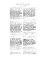
C. SUPPLY FROM SHIP'S FUEL SYSTEM TO ENGINE FUEL SYSTEMS
5C1. General. After leaving the
collecting tank, fuel is piped through a
system comprised of strainers, fuel
meters, fuel oil transfer pumps,
purifiers, and clean fuel oil tanks before
reaching the engine. This section of the
fuel oil system is divided into two
parts. One part serves the forward
engine room, the other the after engine
room. The two are interconnected to
provide flexibility of operation.
5C2. Strainers and meters. Fuel oil to
be used in the engine is normally taken
from the top of the collecting tank. It
may, however, in some installations, be
drawn directly from the fuel oil filling
and transfer line. In either case, the oil
should go through a wire mesh type
strainer and fuel meter before entering
the suction side of the fuel oil transfer
pump. Both strainer and meter are fitted
with bypass connections by means of
which a strainer, or meter, or both may
be bypassed.
5C3. Fuel oil transfer and purifier
pumps. Located in each engine room is
a positive displacement type fuel oil
transfer and purifier pump, driven by an
electric motor. The primary function of
this pump is to transfer fuel oil from the
collecting tank to the clean fuel oil tank
through the purifier. It may also be used
for priming purposes by taking a suction
from the clean fuel oil tank and
delivering the priming oil to the
individual engine fuel system. An engine
normally is primed before starting,
particularly if it has been secured for
some time.
Under normal operating conditions this
pump is operated until the clean fuel oil
tanks are full. It is then secured until the
level of oil in the clean fuel oil tanks
becomes such as to indicate need for
replenishment.
5C4. Pure oil purifiers. a. General. The
fuel oil purifiers are Sharples centrifuge
units which operate on the principle of
centrifugal force.
Centrifugal force is the force exerted
upon a body or substance by rotation that
impels that body or substance outward
from the axis of rotation. When a mixture
of liquids is revolved at high speed in a
container, the centrifugal force causes the
components of the liquid to separate. The
component with the greatest specific
gravity will assume the outermost
position, and the lightest component, the
innermost position. Thus, if a mixture of
water and oil is revolved, the water,
being the heavier component, will
separate from the lighter oil and form
100
Figure 5-4. Fuel oil supply from ship's fuel system to engine fuel system in one engine room.
a layer around the wall of the container,
while the oil remains near the center of
the container. The Sharples fuel oil
purifier operates on this principle.
The Sharples purifier can be used as a
separator or a clarifier. When used as a
separator, the purifier separates oil
from water and solid sediment. When
used as a clarifier, it separates oil from
solid sediment only. The unit is usually
set up as a separator in fuel oil systems
and a clarifier in lube oil systems. (See
Section 7B7.)
b. Operation. The fuel oil transfer and
purifier pump forces fuel oil through a
short connecting line at the bottom of
the purifier bowl. The purifier bowl is
revolved by an attached electric motor
at about 15,000 rpm. A three-wing
partition extends the full length of the
bowl on the inside. The purpose of this
partition is to keep the liquid in the
bowl revolving with the bowl.
Otherwise there would be slippage of
the liquid column which would
reduce the effect of the centrifugal force.
When the machine is operated as a
separator, the bowl is primed with fresh
water until an effective water seal is
created at the water discharge outlet. The
water priming line is sealed off from the
fuel inlet line by means of a check valve
which prevents water from finding its
way into the fuel system. Then the fuel
oil supply is forced into the swiftly
revolving bowl. The centrifugal force
throws the water, which has a heavier
specific gravity than the oil, to the
outside wall of the bowl and creates a
vertical layer of water at this outer
extremity. The fuel oil, which has a
lighter specific gravity, forms a layer
next to the water. Any particles of
sediment in the fuel oil have a heavier
specific gravity than either the water or
oil and are drawn and held against the
wall of the bowl by the centrifugal force.
Dirt and sediment are cleaned out of the
bowl when necessary.
At the top of the purifier bowl is a barrier
called a ring dam, which covers the top