Tài liệu Circulat doc
Bạn đang xem bản rút gọn của tài liệu. Xem và tải ngay bản đầy đủ của tài liệu tại đây (29.93 KB, 2 trang )
1
2
3
1
3
2
1
3
2
10 to 12 GHz
8 to 10 GHz
8 to 12 GHz
FILTER
Filter could be a
piece of waveguide
which passes
above 10 GHz
OUTPUT
INPUT
HIGH PASS
OUTPUT
6-7.1
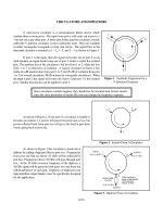
Figure 1. Symbolic Expression for a
Y-Junction Circulator
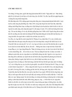
Figure 2. Isolator From A Circulator
Figure 3. Diplexer From A Circulator
CIRCULATORS AND DIPLEXERS
A microwave circulator is a nonreciprocal ferrite device which
contains three or more ports. The input from port n will come out at port n +
1 but not out at any other port. A three-port ferrite junction circulator, usually
called the Y-junction circulator, is most commonly used. They are available
in either rectangular waveguide or strip- line forms. The signal flow in the
three-port circulator is assumed as 1v2, 2v3, and 3v1 as shown in Figure 1.
If port 1 is the input, then the signal will come out of port 2; in an
ideal situation, no signal should come out of port 3 which is called the isolated
port. The insertion loss of the circulator is the loss from 1 to 2, while the loss
from 1 to 3 is referred to as isolation. A typical circulator will have a few
tenths of a dB insertion loss from port 1 to 2 and 20 dB of isolation from port
1 to 3 for coaxial circulators (30 dB or more for waveguide circulators). When
the input is port 2, the signal will come out of port 3 and port 1 is the isolated
port. Similar discussions can be applied to port 3.
Since circulators contain magnets, they should not be mounted near ferrous metals
since the close proximity of metals like iron can change the frequency response.
As shown in Figure 2, if one port of a circulator is loaded, it
becomes an isolator, i.e. power will pass from ports one to two, but
power reflected back from port two will go to the load at port three
versus going back to port one.
As shown in Figure 3 this circulator is made into a
diplexer by adding a high pass filter to port two. Frequencies
from port one that are below 10 GHz will be reflected by
port two. Frequencies above 10 GHz will pass through port
two. At the 10 GHz crossover frequency of the diplexer, a
10 GHz signal will be passed to both ports two and three but
will be half power at each port. Diplexers or triplexers (one
input and three output bands), must be specifically designed
for the application.
10 kW 1 kW
Water
Load
Receiver/Measurment Device (9 mW)
ANTENNA
VSWR 2:1
Reflected power down 10 dB
POWER
INPUT
SOURCE
CW
Reflected power now down
9 kW
40 dB attenuator
1 kW *
0.9 kW
100 W *
10 W *
100 W
* All loads and the
antenna have a
2:1 VSWR
20 dB from power input
** If reverse leakage is not
attenuated by at least 20 dB,
this leakage path dominates
at the measurement port.
Normally, a coaxial circulator
will have at least 20 dB of
reverse attenuation and a
waveguide circulator will
have at least 30 dB of
reverse attenuation.
**
AFT FWD
Low
Rx
Low
Tx
Hybrid
AFT FWD
Low
Rx
Low
Tx
Hybrid
High
Rx
High
Tx
* High
power
device
*
*
AFT FWD
Low
Rx
Low
Tx
Hybrid
High
Rx
High
Tx
High
power
device
Low
power
device
L
H
L
H
6-7.2
Figure 4. Faraday Rotator Circulator
Figure 5. Low Band Configuration
Figure 6. Low/High Band Configuration Figure 7. Alternate Low/High Band Configuration
Another useful device is the
4-port Faraday Rotator Circulator
shown symbolically in Figure 4. These
waveguide devices handle very high
power and provide excellent isolation
properties. It is useful when
measurements must be made during
high power application as shown. A
water load is used to absorb the high
power reflections so that a reasonable
power level is reflected to the receiver
or measurement port.
The Maximum Input Power to
a Measurement Device - The ideal
input to a measurement device is in the
0 to 10 dBm ( 1 to 10 mW) range.
Check manufacturer's specification for
specific maximum value.
If the RF transmission lines and their components
(antenna, hybrid, etc.) can support the wider frequency range,
circulators could be used to increase the number of
interconnecting RF ports from two as shown in Figure 5, to four
as shown in Figure 6. Figure 7 shows an alternate configuration
using diplexers which could actually be made from circulators as
shown previously in Figure 3.