Tài liệu Mobile Satellite Communication Networks pptx
Bạn đang xem bản rút gọn của tài liệu. Xem và tải ngay bản đầy đủ của tài liệu tại đây (4.46 MB, 382 trang )
Mobile Satellite
Communication Networks
Mobile Satellite Communication Networks. Ray E. Sheriff and Y. Fun Hu
Copyright q 2001 John Wiley & Sons Ltd
ISBNs: 0-471-72047-X (Hardback); 0-470-845562 (Electronic)
Mobile Satellite
Communication Networks
Ray E. Sheriff and Y. Fun Hu
Both of
University of Bradford, UK
JOHN WILEY & SONS, LTD
Copyright q 2001 by John Wiley & Sons, Ltd
Baffins Lane, Chichester,
West Sussex, PO19 1UD, England
National 01243 779777
International (+44) 1243 779777
e-mail (for orders and customer service enquiries):
Visit our Home Page on or
All Rights Reserved. No part of this publication may be reproduced, stored in a retrieval system, or
transmitted, in any form or by any means, electronic, mechanical, photocopying, recording, scanning or
otherwise, except under the terms of the Copyright Designs and Patents Act 1988 or under the terms of a
licence issued by the Copyright Licensing Agency, 90 Tottenham Court Road, London, W1P 9HE, UK,
without the permission in writing of the Publisher, with the exception of any material supplied speci-
fically for the purpose of being entered and executed on a computer system, for exclusive use by the
purchaser of the publication.
Neither the author(s) nor John Wiley & Sons Ltd accept any responsibility or liability for loss or damage
occasioned to any person or property through using the material, instructions, methods or ideas
contained herein, or acting or refraining from acting as a result of such use. The author(s) and Publisher
expressly disclaim all implied warranties, including merchantability of fitness for any particular
purpose.
Designations used by companies to distinguish their products are often claimed as trademarks. In all
instances where John Wiley & Sons is aware of a claim, the product names appear in initial capital or
capital letters. Readers, however, should contact the appropriate companies for more complete informa-
tion regarding trademarks and registration.
Other Wiley Editorial Offices
John Wiley & Sons, Inc., 605 Third Avenue,
New York, NY 10158-0012, USA
WILEY-VCH Verlag GmbH
Pappelallee 3, D-69469 Weinheim, Germany
John Wiley & Sons Australia Ltd, 33 Park Road, Milton,
Queensland 4064, Australia
John Wiley & Sons (Canada) Ltd, 22 Worcester Road
Rexdale, Ontario, M9W 1L1, Canada
John Wiley & Sons (Asia) Pte Ltd, 2 Clementi Loop #02-01,
Jin Xing Distripark, Singapore 129809
British Library Cataloguing in Publication Data
A catalogue record for this book is available from the British Library
ISBN 0471 72047 X
Typeset in Times by Deerpark Publishing Services Ltd, Shannon, Ireland.
Printed and bound in Great Britain by T. J. International Ltd, Padstow, Cornwall.
This book is printed on acid-free paper responsibly manufactured from sustainable forestry, in which at
least two trees are planted for each one used for paper production.
Contents
Preface ix
Acknowledgements xi
Figures xiii
Tables xvii
1 Mobile Communication System Evolution 1
1.1 Historical Perspective 1
1.2 Cellular Systems 2
1.2.1 Basic Concepts 2
1.2.2 First-Generation (1G) Systems 6
1.2.3 Second-Generation (2G) Systems 9
1.2.4 Evolved Second-Generation (2G) Systems 21
1.3 Cordless Telephones 26
1.3.1 Background 26
1.3.2 Cordless Telephone-2 (CT-2) 27
1.3.3 Digital Enhanced Cordless Telecommunications (DECT) 28
1.3.4 Personal Handyphone System (PHS) 30
1.4 Third-Generation (3G) Systems 30
1.4.1 International Mobile Telecommunications-2000 (IMT-2000) 30
1.4.2 Universal Mobile Telecommunications System (UMTS) 35
1.5 Fourth-Generation (4G) Systems 40
References 41
2 Mobile Satellite Systems 43
2.1 Introduction 43
2.1.1 Current Status 43
2.1.2 Network Architecture 44
2.1.3 Operational Frequency 49
2.1.4 Logical Channels 49
2.1.5 Orbital Types 50
2.2 Geostationary Satellite Systems 52
2.2.1 General Characteristics 52
2.2.2 Inmarsat 56
2.2.3 EUTELSAT 61
2.2.4 Asia Cellular Satellite, THURAYA and Other Systems 63
2.3 Little LEO Satellites 65
2.3.1 Regulatory Background 65
2.3.2 ORBCOMMe 66
2.3.3 E-SATe 67
2.3.4 LEO ONEe 68
2.3.5 Other Systems 68
2.4 Satellite-Personal Communication Networks (S-PCN) 69
2.4.1 General Characteristics 69
2.4.2 IRIDIUMe 70
2.4.3 GLOBALSTARe 71
2.4.4 NEW ICOe 74
2.4.5 CONSTELLATION COMMUNICATIONSe 77
2.4.6 ELLIPSOe 77
References 81
3 Constellation Characteristics and Orbital Parameters 83
3.1 Satellite Motion 83
3.1.1 Historical Context 83
3.1.2 Equation of Satellite Orbit – Proof of Kepler’s First Law 84
3.1.3 Satellite Swept Area per Unit Time – Proof of Kepler’s Second Law 86
3.1.4 The Orbital Period – Proof of Kepler’s Third Law 87
3.1.5 Satellite Velocity 88
3.2 Satellite Location 89
3.2.1 Overview 89
3.2.2 Satellite Parameters 90
3.2.3 Satellite Location in the Orbital Plane 91
3.2.4 Satellite Location with Respect to the Rotating Earth 93
3.2.5 Satellite Location with Respect to the Celestial Sphere 94
3.2.6 Satellite Location with Respect to Satellite-Centred Spherical Co-ordinates 95
3.2.7 Satellite Location with Respect to the Look Angles 97
3.2.8 Geostationary Satellite Location 100
3.3 Orbital Perturbation 101
3.3.1 General Discussion 101
3.3.2 Effects of the Moon and the Sun 101
3.3.3 Effects of the Oblate Earth 103
3.3.4 Atmospheric Drag 104
3.4 Satellite Constellation Design 104
3.4.1 Design Considerations 104
3.4.2 Polar Orbit Constellation 106
3.4.3 Inclined Orbit Constellation 111
References 114
4 Channel Characteristics 115
4.1 Introduction 115
4.2 Land Mobile Channel Characteristics 115
4.2.1 Local Environment 115
4.2.2 Narrowband Channel Models 118
4.2.3 Wideband Channel Models 127
4.3 Aeronautical Link 128
4.4 Maritime Link 129
4.5 Fixed Link 129
4.5.1 Tropospheric Effects 129
4.5.2 Ionospheric Effects 142
References 143
5 Radio Link Design 147
5.1 Introduction 147
5.2 Link Budget Analysis 148
vi
Contents
5.2.1 Purpose 148
5.2.2 Transmission and Reception 148
5.2.3 Noise 152
5.2.4 Satellite Transponder 158
5.3 Modulation 163
5.3.1 Overview 163
5.3.2 Phase Shift Keying 163
5.3.3 Minimum Shift Keying 168
5.3.4 Quadrature Amplitude Modulation (QAM) 168
5.4 Channel Coding 168
5.4.1 Background 168
5.4.2 Block Codes 169
5.4.3 Convolutional Codes 174
5.4.4 Interleaving 180
5.4.5 Concatenated Codes 181
5.4.6 Turbo Codes 181
5.4.7 Automatic Repeat Request Schemes 182
5.5 Multiple Access 184
5.5.1 Purpose 184
5.5.2 FDMA 186
5.5.3 TDMA 186
5.5.4 CDMA 188
5.5.5 Contention Access Schemes 193
5.5.6 S-UMTS/IMT-200 Candidate Solutions 194
References 195
6 Network Procedures 197
6.1 Introduction 197
6.2 Signalling Protocols 198
6.2.1 Overview of GSM Signalling Protocol Architecture 198
6.2.2 S-PCN Interfaces and Signalling Protocol Architecture 199
6.3 Mobility Management 201
6.3.1 Satellite Cells and Satellite Location Areas 201
6.3.2 Location Management 202
6.3.3 Handover Management 220
6.4 Resource Management 224
6.4.1 Objectives 224
6.4.2 Effects of Satellite System Characteristics 225
6.4.3 Effects of Mobility 226
6.4.4 Resource Allocation Strategies 227
6.4.5 Network Operations and Procedures 231
References 243
7 Integrated Terrestrial-Satellite Mobile Networks 247
7.1 Introduction 247
7.2 Integration with PSTN 248
7.2.1 Introduction 248
7.2.2 Gateway Functions and Operations 248
7.2.3 Protocol Architecture of SSN7 249
7.2.4 Access Functions 253
7.3 Integration with GSM 254
7.3.1 Introduction 254
7.3.2 Integration Requirements 256
7.3.3 Integration Scenarios 258
Contents vii
7.3.4 Impact of Integration Scenarios on the Handover Procedure 261
7.3.5 Impact of Integration Scenarios on the Location Management Procedure 275
7.3.6 Impact of Integration Scenarios on the Call Set-up Procedure 280
7.3.7 The Role of Dual-mode Terminal in Terrestrial/S-PCN Integration 283
7.4 Integration with Third Generation (3G) Networks 287
7.4.1 Concept of Interworking Units 287
7.4.2 The Radio-Dependent and Radio-Independent Concept 288
7.4.3 Satellite Integration with UMTS – a UTRAN Approach 289
7.4.4 Satellite Integration with GSM/EDGE – a GERAN Approach 290
7.4.5 Conclusion 291
References 291
8 Market Analysis 293
8.1 Introduction 293
8.2 Historical Trends in Mobile Communications 295
8.3 Prospective Satellite Markets 297
8.3.1 Objectives 297
8.3.2 The Role of Satellites 297
8.3.3 Satellite Markets 298
8.3.4 Service Categories 299
8.4 Future Market Forecast 301
8.4.1 Terminal Classes 301
8.4.2 Market Segmentation 302
8.4.3 Sizing the Market 305
8.4.4 Data Sources 308
8.5 Results 309
8.5.1 Tariff 309
8.5.2 Portable Market 310
8.5.3 Mobile Market 311
8.5.4 Total Market 315
8.6 Concluding Remarks 316
References 318
9 Future Developments 319
9.1 Introduction 319
9.2 Super GEOs 320
9.3 Non-Geostationary Satellites 323
9.4 Hybrid Constellations 324
9.5 Mobile-Broadband Satellite Services 325
9.6 Mobile IP 328
9.7 Transmission Control Protocol (TCP) 330
9.7.1 Overview 330
9.7.2 Congestion Window and Slow Start Threshold 331
9.7.3 Loss Recovery Mechanisms 331
9.7.4 Future Work 332
9.8 Fixed-Mobile Convergence 333
9.9 High Altitude Platforms 334
9.10 Location Based Service Delivery 337
9.11 Concluding Remarks 338
References 339
Appendix A: Acronyms 341
Appendix B: Symbols 351
Index 359
Contentsviii
Preface
The last decade proved to be hugely successful for the mobile communications industry,
characterised by continued and rapid growth in demand, spurred on by new technological
advances and innovative marketing techniques. Of course, when we refer to mobile commu-
nications, we tend to implicitly refer to cellular systems, such as GSM. The plight of the
mobile-satellite industry over the last decade, although eventful, has, at times, been more akin
to an out of control roller coaster ride. From an innovative start, the industry is now in the
process of re-assessing, if not re-inventing itself. While niche satellite markets have contin-
ued to grow steadily over the last 10 years, the significant market penetration derived from
personal mobile services via satellite that was anticipated at the start of the decade has failed
to materialise. With this in mind, it may seem like a strange time to bring out a book on
mobile-satellite communication networks.
Certainly, if we were to have produced a book merely describing the technology behind
mobile-satellite networks, then in many respects, we would have failed to address the real
issues that affect mobile-satellite systems, namely the influence of terrestrial mobile commu-
nications and an assessment of the market, which ultimately decides whether a system is
viable or not. With this in mind, we have put together a book which aims to highlight these
key issues, while at the same time covering the fundamentals of the subject. We believe this
combination provides a unique approach to the subject that is relevant to those involved in the
mobile-satellite industry.
With this approach in mind, the first chapter reflects on the status of the mobile commu-
nications industry. It is now accepted that mobile-satellite communications will largely play
complementary roles to their terrestrial counterparts. Consequently, it is important to have an
understanding of the different types of mobile communications systems that are presently
available. This chapter covers the development of cellular and cordless communications from
their initial beginnings to the present day.
This is followed in Chapter 2 by a review of the current state of the mobile-satellite
industry. Usually, when we discuss mobile communications, invariably we will associate
this with voice communications. However, satellites are also used for other innovative
services such as store-and-forward data relaying and vehicular fleet management. This chap-
ter considers all aspects of mobile-satellite communications from the established geostation-
ary systems to the latest ‘‘ little’’ and ‘‘ big’’ low Earth orbit systems.
The introduction of non-geostationary satellite systems often requires the design of
complex multi-satellite constellations. Chapter 3 presents the theory behind the design of
such networks. This is followed in Chapter 4 by a discussion of the properties of the commu-
nication channel, from both a mobile and fixed perspective. The mobile channel in particular
offers a hostile environment in which to design a reliable communications link. This chapter
reviews the present status of understanding with regard to the characterisation of the channel,
indicating the methods of prediction.
The characteristics of the radio interface are considered in Chapter 5. Here, the transmis-
sion chain is analysed presenting the link budget method of analysis. The chapter includes a
description of applicable modulation and coding techniques and multiple access schemes.
In Chapter 6, the network procedures associated with a mobile-satellite network are
presented. In order to facilitate a smooth integration with terrestrial mobile networks, it is
important that as many of the procedures between the two systems are as similar as possible.
This chapter focuses on two key areas of mobility management, namely location management
and handover management, as well as resource management techniques. In Chapter 7, the
requirements for integration with fixed and mobile networks are presented, highlighting the
requirements for integration with the GSM network.
Chapter 8 presents an analysis of the market potential for mobile-satellite communications.
The methodology for deriving the market is presented, followed by a series of market
predictions. Finally, in Chapter 9, we attempt to predict how the mobile-satellite market
will develop over the coming decade.
Certainly, it has been an interesting time to produce a book of this type. The next 10 years
promise to be as innovative, if not more so, than the last, with the introduction of mobile
multimedia services and a greater influence of the Internet on mobile service evolution. It will
be interesting to see how the mobile-satellite communications industry adapts to meet these
new markets over the next few years.
x Preface
Acknowledgement
The texts extracted from the ITU material have been reproduced with the prior authorisa-
tion of the union as copyright holder.
The sole responsibility for selecting extracts for reproduction lies with the beneficiaries of
this authorisation alone and can in no way be attributed to the ITU.
The complete volumes of the ITU material, from which the texts reproduced are extracted,
can be obtained from:
International Telecommunication Union
Sales and Marketing Service
Place des Nations – CH-1211 Geneva 20 (Switzerland)
Telephone: +41-22-730-6141 (English)/+41-22-730-6142 (French)/
+41-22-730-6143 (Spanish)
Telex: 421 000 uit ch/Fax: +41-22-730-5194
X.400 : S ¼ sales; P ¼ itu; A ¼ 400net; C ¼ ch
E-mail: / />Figures
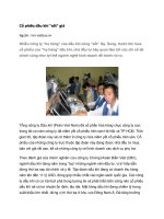
Figure 1.1 Seven-cell frequency re-use pattern 4
Figure 1.2 Basic cellular network architecture 6
Figure 1.3 GSM TDMA 26-frame structure 11
Figure 1.4 GSM full-rate speech coder 12
Figure 1.5 GSM simplified network architecture 13
Figure 1.6 D-AMPS time-slot structure 16
Figure 1.7 cdmaOne forward traffic modulation 19
Figure 1.8 cdmaOne reverse traffic modulation 20
Figure 1.9 GPRS network architecture 23
Figure 1.10 CT-2 frame structure 27
Figure 1.11 DECT frame structure 28
Figure 1.12 DECT network architecture 30
Figure 1.13 IMT-2000 family of radio systems 34
Figure 1.14 IMT-2000 spectral allocation 35
Figure 1.15 UMTS cell types 37
Figure 1.16 UMTS network architecture 39
Figure 1.17 UTRAN architecture 39
Figure 1.18 Grouping of UMTS physical entities 40
Figure 2.1 Mobile-satellite network architecture 44
Figure 2.2 Gateway internal structure 45
Figure 2.3 Possible S-PCN architectures for global coverage 48
Figure 2.4 Minimum three geostationary satellite configuration 55
Figure 2.5 (a) Single-hop, (b) double-hop transmissions 55
Figure 2.6 Inmarsat service coverage (courtesy of Inmarsat) 58
Figure 2.7 An example GAN terminal (courtesy of Nera Telecommunications) 60
Figure 2.8 EUTELTRACS network architecture 61
Figure 2.9 THURAYA mobile terminal (courtesy of Boeing Satellite Systems Inc.) 64
Figure 2.10 ORBCOMM network architecture 67
Figure 2.11 GLOBALSTAR forward traffic modulation for Rate Set 1 73
Figure 2.12 NEW ICO satellite and constellation (courtesy of NEW ICO) 76
Figure 2.13 ELLIPSO orbital characteristics 77
Figure 3.1 Satellite orbital plane 87
Figure 3.2 Area swept by the radius vector per unit time 87
Figure 3.3 Satellite parameters in the geocentric-equatorial co-ordinate system 90
Figure 3.4 Satellite location with respect to an orbital plane co-ordinate system 91
Figure 3.5 The rotating Earth system with respect to the fixed Earth system [PRI-93] 94
Figure 3.6 Celestial sphere co-ordinate system 95
Figure 3.7 Satellite location in satellite-centred spherical co-ordinates 96
Figure 3.8 Satellite location with respect to the look angle 99
Figure 3.9 Coverage area by a satellite at an altitude h 105
Figure 3.10 Ground swath coverage 106
Figure 3.11 Coverage geometry for polar orbit optimisation 107
Figure 3.12 Coverage area beyond a specified latitude value 108
Figure 3.13 Single geometry for single satellite coverage above latitude f 110
Figure 3.14 Geometry for inclined orbit constellation optimisation 112
Figure 3.15 Triangle triad used by Ballard for optimisation of the arc range w 113
Figure 4.1 Mobile network propagation environment 116
Figure 4.2 Fading at 1.5 GHz due to roadside shadowing versus path elevation angle 120
Figure 4.3 Two-state Markov process indicating shadowed and un-shadowed operation 126
Figure 4.4 Specific attenuation due to atmospheric gasses 130
Figure 4.5 Total dry air and water vapour attenuation at the zenith from sea level 132
Figure 4.6 Relationship between slant path length and rain height 133
Figure 4.7 Rain intensity (mm/h) exceeded for 0.01% of an average year 134
Figure 4.8 Predicted (Watson–Hu model) and measured attenuation at Lario station (Italy) 138
Figure 4.9 Generalised elliptical waveform also illustrating: (a) vertical polarisation,
(b) horizontal polarisation, (c) left hand circular polarisation, (d) right hand
circular polarisation. The direction of travel is into the paper 140
Figure 4.10 Faraday rotation as a function of TEC and frequency 142
Figure 5.1 Simplified transmission chain 147
Figure 5.2 Antenna gain characteristics 149
Figure 5.3 Reference radiation pattern for vehicle mounted antennas operating in the 1–3
GHz band 150
Figure 5.4 Variation in antenna gain with frequency 151
Figure 5.5 Free space loss of: LEO (1000 km); MEO (10000 km); and GEO 152
Figure 5.6 Typical receiver chain 153
Figure 5.7 Brightness temperature variation with frequency for extra terrestrial noise sources 154
Figure 5.8 Noise figure variation 156
Figure 5.9 Composite transmission chain 158
Figure 5.10 Simple transparent transponder 158
Figure 5.11 Satellite TWTA operational characteristics 159
Figure 5.12 Multi-carrier payload configuration 160
Figure 5.13 SS-TDMA payload employing microwave switching 161
Figure 5.14 Comparison of: (a) ASK; (b) FSK; and (c) PSK 163
Figure 5.15 QPSK modulation 164
Figure 5.16 PSK phasor diagrams: (a) BPSK; (b) QPSK; (c) 8-PSK 164
Figure 5.17 PSK demodulator 165
Figure 5.18 D-PSK demodulator 166
Figure 5.19 Relationship between P
s
and E
b
/N
0
167
Figure 5.20 Signal space diagrams: (a) MSK; (b) 16-QAM 168
Figure 5.21 RS code structure 173
Figure 5.22 Half-rate convolutional encoder of constraint length 3 173
Figure 5.23 State diagram representation 175
Figure 5.24 Tree diagram representation 177
Figure 5.25 Trellis diagram representation 178
Figure 5.26 Minimum path trellis diagram 178
Figure 5.27 Interleaver/de-interleaver application 179
Figure 5.28 Interleaver block 180
Figure 5.29 Turbo code encoder/decoder 182
Figure 5.30 ARQ schemes: (a) stop-and-wait; (b) continuous ARQ with repeat;
(c) continuous ARQ with selective repeat 184
Figure 5.31 Multi-carrier usage of shared transponder bandwidth 185
Figure 5.32 FDM/FM/FDMA application 185
Figure 5.33 Typical TDMA frame structure 187
Figure 5.34 FDMA/TDMA hybrid access scheme 187
Figure 5.35 PN sequence auto-correlation function R(t) 189
Figure 5.36 Direct sequence CDMA 189
Figure 5.37 DS-CDMA interference rejection capability 191
Figure 5.38 Frequency hopped CDMA 192
Figuresxiv
Figure 5.39 Comparison of: (a) direct sequence and (b) frequency hopping CDMA techniques 192
Figure 6.1 GSM signalling protocols and distribution among network elements 198
Figure 6.2 Functional interfaces of a GMR system 200
Figure 6.3 Location management operations 203
Figure 6.4 Location area under guaranteed coverage area based approach 204
Figure 6.5 Partial GCA 205
Figure 6.6 Location area for terminal position approach 207
Figure 6.7 A fully distributed database architecture 212
Figure 6.8 Database partitioning 213
Figure 6.9 Database hierarchy 213
Figure 6.10 Intra-satellite inter-spot-beam handover 216
Figure 6.11 Inter-satellite handover 216
Figure 6.12 Inter-FES handover 217
Figure 6.13 Terrestrial to satellite handover 218
Figure 6.14 Satellite to terrestrial handover 219
Figure 6.15 Hard handover 222
Figure 6.16 Switched diversity handover 223
Figure 6.17 Combined diversity handover 223
Figure 6.18 Signalling diversity 224
Figure 6.19 Satellite spot-beam cellular concept 228
Figure 6.20 DCA concept in cellular systems 230
Figure 6.21 First user registration information flow [CEC-95] 238
Figure 6.22 Subsequent user-registration information flow [CEC-95] 239
Figure 6.23 Call set-up – outgoing call information flow 240
Figure 6.24 Call set-up – incoming call information flow 241
Figure 6.25 Mobile terminal initiated call release information flow 242
Figure 6.26 Network initiated call release information flow 243
Figure 7.1 S-PCN-PSTN signalling connection 248
Figure 7.2 S-PCN-PSTN gateway function 249
Figure 7.3 SSN7 signalling architecture 250
Figure 7.4 Routing label of SSN7 251
Figure 7.5 S-PCN-PSTN access function 253
Figure 7.6 S-PCN-GSM integration scenarios 258
Figure 7.7 Integration at the Abis interface – common BSC 259
Figure 7.8 Integration at the A interface – common MSC 259
Figure 7.9 Integration at the E interface – separate MSC 260
Figure 7.10 Integration at the U
m
interface 261
Figure 7.11 Signalling flow for a GSM cell to a satellite spot-beam handover for integration
at the E-interface [CEC-95] 263
Figure 7.12 GSM Inter-BSS handover protocol 270
Figure 7.13 GSM-to-satellite handover for integration at the A-interface – scenario 1 [CEC-95] 271
Figure 7.14 GSM-to-satellite handover for integration at the A-interface – scenario 2 [CEC-95] 272
Figure 7.15 Satellite to GSM handover – scenario 1 [CEC-95] 274
Figure 7.16 Satellite to GSM handover – scenario 2 [CEC-95] 275
Figure 7.17 GSM location updating signalling flow [CEC-95] 277
Figure 7.18 S-PCN location update for GCA based approach [CEC-95] 278
Figure 7.19 S-PCN location update for TP based approach [CEC-95] 279
Figure 7.20 Call set-up procedure [CEC-95] 281
Figure 7.21 Mapping of IMUIs and TMTIs onto different network segments for a group DMT 282
Figure 7.22 Mapping of the same IMUI onto different TMTIs with different network segments
through two different DMTs 286
Figure 7.23 Re-registration mechanism for changing service association – scenario 1 286
Figure 7.24 Re-registration mechanism for changing service association – scenario 2 287
Figure 7.25 Initial UMTS mobile equipment domain and core networks concept [ETS-98] 288
Figure 7.26 Radio-dependent and radio-independent concept 288
Figures xv
Figure 7.27 First phase evolution: from GSM/GPRS to UMTS 289
Figure 7.28 First phase integration of 2G systems into UMTS [DEL-99] 290
Figure 7.29 A GERAN-based UMTS network architecture 291
Figure 8.1 Global GSM availability at the turn of the century 294
Figure 8.2 Cellular subscribers in Europe at the turn of the century 295
Figure 8.3 Cellular penetration in Europe at the turn of the century 296
Figure 8.4 Cellular penetration against affordability 304
Figure 8.5 Logistic model curve characteristics 304
Figure 8.6 Market demand for mobile communications 305
Figure 8.7 Mobile market flowchart 308
Figure 8.8 Portable market flowchart 309
Figure 8.9 Total portable market for EU-15 states 311
Figure 8.10 Total EU-15 portable market over a 14-year period 312
Figure 8.11 Total world market for portable terminals over a 14-year period 312
Figure 8.12 Global market share of portable terminals 313
Figure 8.13 Total mobile market for EU-15 states 313
Figure 8.14 Total world market for mobile terminals over a 14-year period 314
Figure 8.15 Global market share of mobile terminals 314
Figure 8.16 Total market for S-UMTS terminals in EU-15 states 315
Figure 8.17 Total market take-up for S-UMTS terminals in EU-15 states 315
Figure 8.18 World market take-up for S-UMTS terminals 316
Figure 8.19 Global market share of S-UMTS terminals 317
Figure 9.1 Cellular market in Africa mid-2000 321
Figure 9.2 Number of telephone lines per 100 inhabitants in Africa 322
Figure 9.3 Possible future hybrid constellation scenario 325
Figure 9.4 Satellite and GPRS integration scenario 329
Figure 9.5 A possible hybrid direct video broadcast service scenario 334
Figure 9.6 Stratospheric platform scenario 335
Figuresxvi
Tables
Table 1.1 GSM terminal classes 10
Table 1.2 GSM logical control channels 13
Table 1.3 GPRS MS operational modes 22
Table 1.4 GPRS logical control channels 23
Table 1.5 DECT slot types 29
Table 2.1 Frequency band terminology 49
Table 2.2 S-TCCH categories 50
Table 2.3 Satellite control channel categories 51
Table 2.4a Comparison of satellite orbits: operational considerations 53
Table 2.4b Comparison of satellite orbits: implementation considerations 54
Table 2.5 Inmarsat satellite configuration 57
Table 2.6 Little LEO frequency allocations below 500 MHz 65
Table 2.7 Allocation of mobile-satellite service frequencies in the L-/S-bands 69
Table 2.8 S-PCN characteristics: satellite and orbit 78
Table 2.9 S-PCN characteristics: services 79
Table 2.10 S-PCN characteristics: radio interface 80
Table 3.1 Value of M
m
for Julian dates calculation 94
Table 3.2 Value of the azimuth angle j with respect to the relative position of the
sub-satellite point 99
Table 3.3 Requirements of p, s, F and w for single coverage of the entire Earth [BES-78] 108
Table 3.4 Requirements of p, s, F and w for triple coverage of the entire Earth [BES-78] 109
Table 3.5 Best single visibility rosette constellations for N ¼ 5–15 [BAL-80] 113
Table 4.1 ERS model characteristics 119
Table 4.2 Fades exceed (dB) at 808 elevation [ITU-99a] 121
Table 4.3 ITU-R regression coefficients for estimating attenuation 135
Table 5.1 Example link budget 157
Table 5.2 Example of D-PSK coding table 166
Table 5.3 Modulo-2 arithmetic 170
Table 6.1 Additional logical channels in the physical layer 201
Table 6.2 Handover phases and strategies 214
Table 6.3 Advantages and disadvantages of different handover controlling schemes 221
Table 7.1 Similarities and differences between a satellite network and a GSM network 255
Table 7.2 Information elements in the ‘‘ handover request’’ message in GSM 264
Table 7.3 Serving cell identifier field format 264
Table 7.4 Handover request ack message format 264
Table 7.5 Handover command message format 265
Table 7.6 Format of the cell description field 265
Table 7.7 User data field in handover required message 267
Table 7.8 Measurement report message format 273
Table 8.1 UMTS terminal service profiles 300
Table 8.2 Possible satellite-UMTS market segmentation 302
Table 8.3 Gross potential market for different terminal classifications 303
Table 8.4 Terrestrial roll-out criteria 307
Table 8.5 Monthly call minutes per terminal type 307
Table 8.6 Data sources 310
Table 8.7 Assumed tariffs at service introduction 310
Table 9.1 Allocation of mobile-satellite service frequencies in the Ka-bands 326
Tablesxviii
1
Mobile Communication
System Evolution
1.1 Historical Perspective
The mobile phone has proved to be one of the most outstanding technological and commer-
cial successes of the last decade. Since its introduction in the 1980s, the phone’s place in the
market place has rapidly progressed from a minority, specialised item to virtually an essential
commodity for both business and leisure use. Over the last two decades, advances in mobile
technology, combined with the significant reduction in operating costs and the development
of new applications and services, have ensured a buoyant market. By mid-2000, there were
over 220 million mobile subscribers in Europe and over 580 million mobile subscribers
world-wide. In the UK, every other person owns a mobile phone; while in Finland the number
of mobile phones per capita now exceeds that of households with fixed phone lines.
As with most technological innovations, the mobile phone’s marketability is not based on
overnight success but rather a systematic, evolutionary development involving multi-national
co-operation at both technical and political levels. In fact, the concept of a mobile phone is
not new. As early as 1947, the cellular concept was discussed within Bell Laboratories [YOU-
79]. However, it was not until the 1970s that technology had developed sufficiently to allow
the commercial implementation of such a system to be investigated.
The evolution of mobile communications can be categorised into generations of develop-
ment. Presently, we are on the verge of the third-generation (3G) of mobile systems. Broadly
speaking, first-generation (1G) systems are those that paved the way and are generally
categorised as being national networks that are based on analogue technology. Such networks
were introduced into service in the 1980s. These networks were designed to provide voice
communications to the mobile user.
Second-generation (2G) systems are categorised by digital technology. They are supported
by international roaming agreements, allowing the possibility to operate a mobile phone across
national boundaries. With the introduction of 2G systems, in addition to digital voice tele-
phony, a new range of low data rate digital services became available, including mobile fax,
voice mail and short message service (SMS) [PEE-00]. Also at this stage in the evolution, new
types of systems began to emerge which catered for particular market needs; not only cellular
mobile, but also cordless, public mobile radio, satellite and wireless-local area network (W-
LAN) solutions. 2G systems are synonymous with the globalisation of mobile systems, and in
Mobile Satellite Communication Networks. Ray E. Sheriff and Y. Fun Hu
Copyright q 2001 John Wiley & Sons Ltd
ISBNs: 0-471-72047-X (Hardback); 0-470-845562 (Electronic)
this respect the importance of standardisation is clear. For example, GSM, which was standar-
dised in Europe by the European Telecommunications Standards Institute (ETSI), is now
recognised as a global standard, with its adoption in most countries of the world. The final
evolutionary phase of 2G networks, in recognition of the importance of the Internet and as a
stepping stone towards the introduction of 3G technology, introduced packet-oriented services,
providing the first opportunity to introduce mobile-multimedia services.
Within the next few years, it is expected that mobile users will wish to access broadband
multimedia services, such as those provided by fixed networks. This demand for broader
bandwidth services is driven by the need to provide services and applications comparable
with those presently available to personal computers (PCs). The phenomenal growth in the
Internet, with over 500 million users predicted by 2005, perfectly illustrates the need for
access to broadband services and applications. These types of services are beyond the
capability of present 2G systems, which offer voice and low data rate services. The conver-
gence of mobile and Internet protocol (IP) based technologies is now the major driving force
behind the development of 3G systems. The 3G mobile communications systems will be
capable of delivering services and applications at data rates of up to and beyond 2 Mbit/s.
The standardisation of 3G systems comes under the overall responsibility of the Interna-
tional Telecommunication Union (ITU). Globally, this will be known as international mobile
telecommunications 2000 (IMT-2000) and will consist of a family systems providing cellu-
lar, cordless, W-LAN and satellite services. In Europe, the 3G system will be known as the
Universal Mobile Telecommunications System (UMTS). Although voice is still likely to be
the dominant application in the first few years of 3G networks, there will also be the possi-
bility to operate mobile-multimedia applications, such as video-telephony, file transfer proto-
col (ftp) file access, Web browsing and so on. As 3G technology evolves, new broader
bandwidth applications will enter the market to such an extent that the transmission of
data will provide the greatest volume of traffic.
Research is now addressing the requirements of fourth-generation (4G) mobile networks.
Mobile data rates beyond 2 Mbit/s, and possibly up to 155 Mbit/s in some environments, will
further extend the services and applications that could be delivered. Improvements in quality
of service (QoS), bandwidth efficiency and the move to an all IP-based, packet-oriented
environment can be envisaged, based on the emerging standards of Mobile IP, under devel-
opment by the Internet Engineering Task Force (IETF) [PER-98, SOL-98]. 4G mobile
networks are likely to be introduced sometime after 2005, possibly as late as 2010.
Although this book is primarily focused on mobile-satellite networks, initially in order to
appreciate the context in which satellite technologies have developed, and the likely applica-
tions for such technologies, it is important to have an understanding of where we are at
present in terms of mobile technology. This chapter aims to provide a flavour of the under-
lying technological developments that have driven the mobile communication industry to the
brink of the establishment of the mobile information society.
1.2 Cellular Systems
1.2.1 Basic Concepts
Cellular networks operate by dividing the service coverage area into zones or cells, each of
which has its own set of resources or channels, which can be accessed by users of the network.
Mobile Satellite Communication Networks2
Usually cellular coverage is represented by a hexagonal cell structure to demonstrate the
concept, however, in practice the shape of cells is determined by the local topography.
Sophisticated planning tools are used extensively by terrestrial cellular operators to assist
with the planning of their cellular networks.
The shape and boundary of a cell is determined by its base station (BS), which provides the
radio coverage. A BS communicates with mobile users through signalling and traffic channels
(TCH). Signals transmitted in the direction from the BS to the mobile are termed the forward
link or downlink, and conversely, the reverse link or uplink is in the direction of mobile to BS.
Signalling channels are used to perform administrative and management functions such as
setting up a call, while TCHs are used to convey the information content of a call. The
allocation of channels to a cell is therefore divided between the TCHs, which form the
majority, and signalling channels. These are allocated for both forward and reverse directions.
In order to increase the capacity of a network, there are three possibilities, either:
1. a greater number of channels are made available;
2. more spectrally efficient modulation and multiple access techniques are employed; or
3. the same channels are re-used, separated by a distance which would not cause an un-
acceptable level of co-channel interference.
Cellular networks, which are limited in terms of available bandwidth, operate using the
principal of frequency re-use. This implies that the same pool of frequencies is re-used in cells
that are sufficiently separated so as not to cause harmful co-channel interference. For a
hexagonal cell structure, it is possible to cluster cells so that no two adjacent cells are
using the same frequency. This is only achievable for certain cell-cluster sizes, which can
be determined from the relationship
N ¼ i
2
1 ij 1 j
2
ð1:1Þ
where i, j ¼ 0, 1, 2, 3, etc.
A seven-cell frequency re-use pattern is shown in Figure 1.1. The total bandwidth available
to the network is divided between cells in a cluster, which can then be used to determine the
number of calls that can be supported in each cell. By reducing the number of cells per cluster,
the system capacity can be increased, since more channels can be available per cell. However,
a reduction in the cluster size will also result in a reduction in the frequency re-use distance,
hence the system may become more prone to co-channel interference.
The frequency re-use distance can be determined for a given cell cluster size from the
equation
D
R
¼
ffiffiffiffi
3N
p
ð1:2Þ
where D is the mean re-use distance, R is the cell radius and N is the cluster size.
In a terrestrial mobile radio environment, the strength of the received carrier power, at a
distance R from the transmitter is related by the following expression:
C /
1
R
g
ð1:3Þ
where
g
is a constant related to the terrain environment, usually assumed to be equal to 4.
Mobile Communication System Evolution 3
For a seven-cell re-use configuration, the ratio of the carrier-to-interference experienced by
a mobile from the six cells located at a minimum re-use distance of D from the mobile, that is
on the first tier of the cell cluster re-use pattern, is given by
C
I
¼
P
D
g
R
g
¼
D
g
6R
g
¼
q
g
6
ð1:4Þ
From the above, q, termed the co-channel interference reduction factor, is given by [LEE-
89]
q ¼
D
R
ð1:5Þ
Note: the above assumes that equal power is radiated by all cells and that the interference
received from cells operating using the same frequency in the second tier of the cell cluster,
can be neglected. Thus, for
g
¼ 4, a seven-cell cluster pattern can provide a C/I ratio of 18 dB.
In order to minimise the effect of co-channel interference, power control techniques are
employed at the mobile terminal and the BS to ensure that power levels are maintained at
the minimum level needed to maintain the target QoS.
How the mobile user gains access to the available channels within a cell is governed by the
multiple access technique used by the network. Analogue cellular networks employ
frequency division multiple access (FDMA), whereas digital networks employ either time
division multiple access (TDMA) or code division multiple access (CDMA). For FDMA, a
seven cell re-use pattern is generally employed, whereas for CDMA a single-cell frequency
re-use pattern is achievable. Further discussions on the advantages and drawbacks of each
technique, in the context of satellite communications, can be found in Chapter 5.
In a terrestrial mobile environment, reception cannot rely on line-of-sight communications
and is largely dependent upon the reception of signal reflections from the surrounding envir-
onment. (Note: This is the opposite of the mobile-satellite case, which is reliant on line-of-
sight operation, and is discussed in detail in Chapter 4.) The resultant scattering and multipath
components arrive at the receiver with random phase. The propagation channel can be
characterised by a combination of a slow-fading, long-term component and a fast-fading,
short-term component. As a consequence of the local terrain, the change in a mobile’s
position relative to that of a transmitting BS will result in periodic nulls in the received signal
strength. This is due to the fact that the vector summation of the multipath and scattering
Mobile Satellite Communication Networks4
Figure 1.1 Seven-cell frequency re-use pattern.
components at the receiver results in a signal envelope of the form of a standing wave pattern,
which has signal nulls at half-wave intervals. For a signal transmitting at 900 MHz, which is
typical for cellular applications, a half-wavelength distance corresponds to approximately
17 cm. This phenomenon is known as slow-fading and is characterised by a log-normal
probability density function.
As the mobile’s velocity, n, increases, the variation in the received signal envelope
becomes much more pronounced and the effect of the Do
¨
ppler shift on the received multipath
signal components also has an influence on the received signal, where Do
¨
ppler shift, f
d
,is
given by
f
d
¼
v
l
cosð
a
Þ Hz ð1:6Þ
where
a
is the angle of arrival of the incident wave.
This phenomenon is termed fast-fading and is characterised by a Rayleigh probability
density function. Such variations in received signal strength can be as much as 30 dB
below or 10 dB above the root mean square signal level, although such extremes occur
infrequently.
In rural areas, where the density of users is relatively low, large cells of about 25 km radius
can be employed to provide service coverage. This was indeed the scenario when mobile
communications were first introduced into service. In order to sustain the mobile to BS link
over such a distance requires the use of a vehicular-type mobile terminal, where available
transmit power is not so constrained in comparison with hand-held devices. With an increase
in user-density, the cell size needs to reduce in order to enable a greater frequency re-use and
hence to increase the capacity of the network. Urban cells are typically of 1 km radius. This
reduction in cell size will also correspond to a reduction in BS and mobile terminal transmit
power requirements. This is particularly important in the latter case, since it paves the way for
the introduction of hand-held terminals.
When a mobile moves from one cell to another during the course of an on-going call, a
handover (also termed handoff) of the call between BSs must be performed in order to ensure
that the call continues without interruption. Otherwise the call will be dropped and the mobile
user would need to re-initiate the call set-up sequence. Handover between BSs involves
monitoring of the signal strength between the mobile to BS link. Once the signal strength
reduces below a given threshold, the network initiates a procedure to reserve a channel
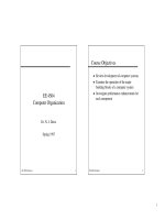
through another BS, which can provide a channel of sufficient signal strength (Figure 1.2).
A number of BSs are clustered together via a fixed-network connection to a mobile switch-
ing centre (MSC), which provides the switching functionality between BSs during handover
and can also provide connection to the fixed or core network (CN) to allow the routing of
calls. The clustering of BSs around a MSC is used to define a Location Area, which can be
used to determine the latest known location of a mobile user. This is achieved by associating
Home and Visitor Location Areas to a mobile. Each mobile is registered with a single home
location register (HLR) upon joining the network. Once a mobile roams outside of its Home
Location Area into a new designated Location Area, it temporarily registers with the network
as a visitor, where its details are stored in a visitor location register (VLR) associated with the
MSC. Each MSC in the network has an associated VLR and HLR. The mobile’s location is
relayed back to its HLR, a database containing various information on the mobile terminal,
some of which is then forwarded to the VLR. The network also comprises of other databases
Mobile Communication System Evolution 5
that can be used to verify that the mobile has access to the network, such as the Authentication
Centre (AuC), for example. These procedures are described later in the chapter for the GSM
system.
1.2.2 First-Generation (1G) Systems
1.2.2.1 Introduction
In the future mobile information society, where mobile-multimedia delivery will be the major
technological driving force, analogue cellular technology has little, if any significance.
Indeed, in many countries across Europe, mobile operators are now switching off their
analogue services in favour of digital technology. However, analogue technologies still
play an important role in many countries around the world, by being able to provide estab-
lished and reliable mobile voice telephony at a competitive price. This section considers three
of the major analogue systems that can still be found with significant customer databases
throughout the world.
1.2.2.2 Nordic Mobile Telephone (NMT) System
On 1 October, 1981, the Nordic NMT450 became the first European cellular mobile commu-
nication system to be introduced into service [MAC-93]. This system was initially developed
to provide mobile communication facilities to the rural and less-populated regions of the
Scandinavian countries Denmark, Norway, Finland and Sweden. NMT450 was essentially
developed for in-car and portable telephones. By adopting common standards and operating
frequencies, roaming between Scandinavian countries was possible. Importantly, the intro-
Mobile Satellite Communication Networks6
Figure 1.2 Basic cellular network architecture.
duction of this new technology provided network operators and suppliers with an early
market lead, one that has been sustained right up to the present day.
As is synonymous of 1G systems, NMT450 is an analogue system. It operates in the 450
MHz band, specifically 453–457.5 MHz (mobile to BS) and 463–467.5 MHz (BS to mobile).
FDMA/FM is employed as the multiple access scheme/modulation method for audio signals,
with a maximum frequency deviation of ^5 kHz. Frequency shift keying (FSK) is used to
modulate control signals with a frequency deviation of ^3.5 kHz. NMT450 operates using a
channel spacing of 25 kHz, enabling the support of 180 channels. Since its introduction, the
NMT450 system has continued to evolve with the development of the NMT450i (where
i stands for improvement) and NMT900 systems.
NMT900 was introduced into service in 1986, around about the same time as other Western
European countries were starting to introduce their own city based mobile cellular-based
solutions. NMT900 is designed for city use, catering for hand-held and portable terminals. It
operates in the 900 MHz band with the ability to accommodate higher data rates and more
channels.
The NMT system continues to hold a significant market share throughout the world and,
significantly, the system continues to evolve, through a series of planned upgrades. In Europe,
the NMT family has a particularly large market share in Eastern European countries, where
mobile telephony is only now starting to become prevalent.
The next phase in the evolution of the NMT450 network, as initiated by the NMT MoU, is
the digitisation of the standard. This is considered an important and necessary evolutionary
phase, in light of competition from existing 2G and future generation mobile networks. This
will be achieved through the down banding of the GSM network, and will be known as
GSM400. The possibility to provide dual-band GSM phones in order to support global
roaming is considered particularly attractive. Towards the end of 1999, Nokia and Ericsson
combined to demonstrate the first call made on a dual-mode GSM400/1800 prototype mobile
phone.
Since 1981, Nordic countries have continued to lead the way with now over 60% of the
population in Finland and Norway having a mobile phone. The Scandinavian-based compa-
nies Nokia and Ericsson are world leaders in mobile phone technology and both are driving
the phone’s evolution forward.
1.2.2.3 Advanced Mobile Phone Service (AMPS)
Bell Labs in the US developed the AMPS communications system in the late 1970s [BEL-79].
The AMPS system was introduced into commercial service in 1983 by AT&T with a 3-month
trial in Chicago. The system operates in the US in the 800 MHz band, specifically 824–849
MHz (mobile to BS) and 869–894 MHz (BS to mobile). These bands offer 832 channels, which
are divided equally between two operators in each geographical area. Of these 832 channels,
42 channels carry only system information. The AMPS system provides a channel spacing of
30 kHz using FM modulation with a 12 kHz peak frequency deviation for voice signals.
Signalling between mobile and BS is at 10 kbit/s employing Manchester coding. The
signals are modulated using FSK, with a frequency deviation of ^8 kHz. The AMPS system
specifies six one-way logical channels for transmission of user and signalling information.
The Reverse TCH and Forward TCH are dedicated to the transmission of user data on a one-
to-one basis. Signalling information is carried to the BS on the channels reverse control
Mobile Communication System Evolution 7
channel (RECC) and reverse voice channel (RVC); and to the mobile using the channels
forward control channel (FOCC) and forward voice channel (FVC).
The forward and reverse control channels are used exclusively for network control infor-
mation and can be referred to as Common Control Channels. To safeguard control channels
from the effect of the mobile channel, information is protected using concatenated pairs of
block codes. To further protect information, an inner code employs multiple repetition of
each BCH (Bose–Chadhuri–Hocquenghem) code word at least five times, and 11 times for
the FVC.
In order to identify the BS assigned to a call, AMPS employs a supervisory audio tone
(SAT), which can be one of three frequencies (5970, 6000 and 6030 Hz). At call set-up, a
mobile terminal is informed of the SAT at the BS to which it communicates. During a call, the
mobile terminal continuously monitors the SAT injected by the BS. The BS also monitors the
same SAT injected by the mobile terminal. Should the received SAT be incorrect at either the
mobile terminal or the BS, the signal is muted, since this would imply reception of a source of
interference.
Like NMT450, the AMPS standard has continued to evolve and remains one of the most
widely used systems in the world. Although market penetration did not reach Europe, at least
in its unmodified form, it remains a dominant standard in the Americas and Asia.
Narrowband-AMPS Motorola developed the narrowband-AMPS (N-AMPS) system in
order to increase the available capacity offered by the network. This was achieved by
dividing the available 30 kHz AMPS channel into three. N-AMPS employs frequency
modulation with a maximum deviation of 5 kHz from the carrier. From the outset, mobile
phones were developed for dual-mode operation allowing operation with the AMPS 30 kHz
channel.
Due to the narrower bandwidth, there is a slight degradation in speech quality when
compared to AMPS. In order to optimise reception, N-AMPS employs a radio resource
management technique called Mobile Reported Interference. This procedure involves the
mobile terminal monitoring the received signal strength of a forward narrow TCH and the
BER on the control signals of the associated control channel. A BS sends the mobile a
decision threshold on the reserve associated control channel, below which handover can be
initiated.
Signalling control channels are transmitted using a continuous 100 bit/s Manchester coded
in-band sub-audible signal. In addition to signalling messages, alphanumeric messages can
also be transmitted to the mobile.
N-AMPS was standardised in 1992 under IS-88, IS-89 and IS-90. In 1993, IS-88 was
combined with the AMPS standard IS-553 to form a single common analogue standard.
1.2.2.4 Total Access Communications System (TACS)
By the mid-1980s, most of Western Europe had mobile cellular capability, although each
country tended to adopt its own system. For example, the C-NETZ system was introduced in
Germany and Austria, and RADIOCOM 2000 and NMT-F, the French version of NMT900
could be found in France. This variety of technology made it impossible for international
commuters to use their phones on international networks, since every national operator had its
own standard. In the UK, Racal Vodafone and Cellnet, competing operators providing tech-
Mobile Satellite Communication Networks8