Tài liệu Lightning Protection and Trees docx
Bạn đang xem bản rút gọn của tài liệu. Xem và tải ngay bản đầy đủ của tài liệu tại đây (442.29 KB, 7 trang )
Source:
Lightning Protection and Trees
Ben Fuest
Introduction - Lightning Protection Systems Fitted to Trees
[The research and recommendations for protecting trees from lightning strikes, and the concomitant protection
afforded to nearby buildings discussed in this article focus on conditions in the U.K. However the principles of tree
protection from lightning discussed here are generally applicable to other countries as well, though the statistics on
the frequency of lightning strike and other local conditions vary. -- Editor]
This research on lightning protection systems for trees was established for the purpose of
developing a better understanding of lightning protection systems specifically designed to be
fitted to trees. Coming from a background in sylviculture my initial concern was to enable
important and intrinsically valuable trees to be protected from damage resulting from lightning
strikes. However it quickly became apparent that the protection of nearby structures and
buildings that might be liable to collateral damage in the event of strike was of equal
significance.
Research showed that on those occasions where lightning protection had been installed in trees,
the system employed had been based upon designs originally intended for use on buildings and
other essentially non-dynamic man made structures. The particular problems of installing the
necessary hardware into living and growing trees did not appear to have been adequately
addressed. Thus the direct effect on the tree of the installation of the required hardware is not
factored in, with the result that trees are likely to be caused some degree of long-term harm in the
very process of attempting to protect them.
The Approach to Lightning Protection for Trees, Passive Cloud-to-Ground
Lightning Protection
This document refers to lightning protection for trees in the UK. The type of lightning considered
is cloud to ground and not inter-cloud as this type is not at present considered to be a threat. In
the UK, we can expect approximately 450,000 - 500,000 strokes per year. Of this approximately
40% is cloud to ground. (EA Technologies cloud to ground database) This is quite low compared
to some countries, but is still considered significant enough in some instances to warrant
lightning protection. I will only be referring to passive lightning protection.
Active systems are not considered, as there is insufficient evidence to support their performance
claims. (The University of Manchester Institute of Science and Technology Test report No:
43427): The need for lightning protection is evaluated either to conserve specimen trees or due to
a concern about collateral damage to surrounding people and property.
We can ascertain the extent of lightning activity in the immediate area around the subject tree by
performing a cloud-to-ground density analysis. Cloud-to-ground lightning produces extra long
wave radiation (low electromagnetic frequency). Low frequency emissions have very good
transmission characteristics in the atmosphere and potentially can travel for hundreds of
kilometers before decaying to an undetectable level.
Generated by Foxit PDF Creator © Foxit Software
For evaluation only.
This frequency is at 1070Hz and transmission is further enhanced by the entrapment of the
ionosphere; this is referred to as wave-guide effect, a useful tool in the evaluation process. It
should be noted that this is a two-dimensional representation of a three-dimensional
phenomenon. As such it will be necessary to look at the topography of the site taking into
account other tall structures, dynamic and non-dynamic.
A lightning protection system is comprised of three main components: air terminal, down
conductor and earth (ground) termination.
The earth (ground) termination is where we will be attempting to direct the huge current in a
manner that minimizes risk to property and people. In the horticultural context we look at soil as
a medium for growing. In the context of lightning protection we look at it as a medium for
conducting electricity.
The ANSI A300 Part 4 recommends designing the earth (ground) termination based on a visual
inspection of the soil and its moisture content. This is not possible as water is an insulator not a
conductor; it is the dissolved salts in the water that give it its conductive properties.
These salts are not detectable with the human eye. We can ascertain the electrical value of the
soil to a given depth using a system sometimes referred to as the four-point test or the Wenner
method. This was first introduced in a paper published in October 1915, A method for testing
soil resistivity, by F. Wenner.
This test enables us to prescribe the number of earth (ground) electrodes to employ for a given
ohms resistance on completion of the earth (ground) termination. This is important if we are to
achieve an effective earth (ground) without over specifying the number of electrodes causing
unnecessary expense and disruption, or too few resulting in an inadequate earth (ground). It has
been my experience that multiple electrodes are required in almost all installations.
Lightning Protection System Electrodes
Generated by Foxit PDF Creator © Foxit Software
For evaluation only.
Electrodes [used for lightning strike protection] come in different sizes. The ones referred to here
are 1.2m (4 feet) in length and 12.5 - 13 mm diameter, and are made from mild steel with a two-
micron copper bond coat. The ends are threaded so that with the aid of a coupler they may be
joined together. The minimum requirement for length is 2.4m (8 feet).
If the working space is limited then it is sometimes best to add one on top of another, 2.4 - 3.6 -
4.8. If there is room to work in, it is possible to install individual electrodes in parallel.
Tip depth is an important factor to be considered when deciding configuration. Tip depth
determines the distance between electrodes. If we install them and they are too close they will
interact and we lose the performance benefits. If they are too far apart we are wasting time,
materials and causing unnecessary disruption (BS 6651 1999).
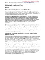
The photograph shown here is an example of how not to protect a tree and a nearby building
from lightning strikes. The owner of this home in New York reported recurrent lightning strikes
on tall trees surrounding the building, but even a casual inspection showed that the lightning
protection system had been badly compromised. It is possible that these conditions actually
increased the risk of damage to this tree and building from lightning.
Soil Conductivity & Lightning Strike Protection
When working with soils of poor conductivity it is possible to introduce soil-conditioning agents.
Bentonite is de-composing volcanic ash; it has hygroscopic properties that enable us to enlarge
the diameter of the earth (ground) electrode without the cost implication. Instead of driving the
electrode into the soil we can drill a hole approximately 25cm (10 inches) wide, and as deep as
the intended electrode, and then back fill with the Bentonite mix.
The lightning protection system electrode is then inserted into this. It should be noted that
Bentonite is an excellent conductor while wet but works just as well as an insulator when dry. If
we are employing this technique, it is useful to remove turf around the hole and put it back on
completion resulting in a more professional finish.
There are alternative ways to overcome poor conductivity. In the past it has been recommended
to install our earth (ground) electrodes just outside the drip line.
Observations show that if the soil around the tree has undergone de-compaction with the addition
of organic mulch, it is possible to obtain a much-improved earth (ground) working just inside the
drip line. With regard to the area affected by the dissipation of the current around the electrode, it
has been observed that this will be contained within a radius of approximately 35-50cm (15-20
inches).
There will be occasions when driving the electrode into the ground it abuts an impenetrable layer
or obstacle. The temptation to cut it will be strong, but I would not be in agreement with this
practice. I would suggest removing the electrode and trying again only this time at an angle of
anything up to 30 degrees from the horizontal; this way we retain the integrity of the electrode
length without the requirement for depth. We can test the value (ohmic resistance) of the earth
(ground) during the installation and on completion; I have found the 62% method to be the most
reliable and industry standard around the world. In the UK the target figure is 10 ohms or less
Generated by Foxit PDF Creator © Foxit Software
For evaluation only.
(BS6651 1999).
Recommendations for Installation of Lightning Protection Systems on Trees
Having established the need for lightning protection and designed the earth (ground) termination
we can look at the aerial aspect of the system. The ANSI A300 Part 4 recommends a maximum
distance between air terminals of 35 feet. I am in agreement with this but, as with all things
organic, there will be exceptions and we should look closely at the tree and see how it lends itself
to the formula and what we think will work best for the circumstances that prevail in the canopy.
Lightning Protection System Conductors on Trees
The conductor should be firmly secured to the fabric of the tree. In the UK we fix at 1 meter (3
feet) intervals; in the US they are specified at a maximum of 1.8 am (6 feet). This difference is
not of any real concern, as I believe we are all of the opinion that the distance will vary with the
form of the tree.
It is however of greater importance to consider the type of fastener we employ. The ANSI A300
Part 4 recommends a type of fastener that is attached to the tree in a manner not dissimilar to a
nail. The conductor is secured at the outer end in a pinch portion. As the tree grows it will
envelop the fastener.
When the incremental growth reaches the pinch portion of the fastener ANSI recommends
removing the conductor from it and installing a new fastener 30 cm (1 foot) above or below the
old one, leaving the old one in the tree. This is a contradiction within the standard and ISA Best
Management Practices (BMP) for Tree Lightning Protection Systems, creating other metallic
conductive objects in the vicinity of the conductor that are not bonded.
The reasons for bonding metallic conductive objects to a component of a lightning protection
system are well established (ANSI A300 Part 4, 46.1.7). The BMP is of the opinion that these
old fasteners will not be subject to potential difference.
Lightning Arcing & Flashover Considerations
It is suggested that these components will be subject to potential difference and an arcing spark is
definitely possible. There exists a common misconception that lightning always takes the path of
Generated by Foxit PDF Creator © Foxit Software
For evaluation only.
least resistance.
It would be more accurate to say that although lightning has a preferred path, it takes all
available paths simultaneously to a lesser or greater extent. Where we have two parallel paths for
the current to flow, the total current will divide in inverse proportion to the resistances
(impedance).
The lightning conductor cable would be the preferred path to ground (primary) but the higher the
resistance of the earth (ground) termination and the higher the impedance in the conductor, the
greater the current in the alternative path (flashover) (Dr V. A. Rakov pers. comm. 2007).
Having seen the conductors in the ANSI system and the recommendations for earth (ground)
termination, it is believed that the systems will be of high impedance.
If we look at the scenario of a system having just undergone an upgrade with new fasteners, the
distance between old fasteners and down conductor is about 10-15 cm (4-6 inches) and is
comprised of air space; so flashover would be in the form of spark/electrical energy. When the
old fastener becomes completely engulfed by new wood the distance remains the same but the
gap is no longer just air space but has a percentage of wood tissue. The difference in terms of
resistance is considerable. In this context resistance is the property of a material to resist the flow
of electrical current. It is specific for a given tissue, depending on its moisture content,
temperature and other physical properties.
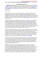
The photograph above was taken at Arlington National Cemetery (Arlington, VA, USA). The
photo shows a system having undergone an upgrade with new fasteners. The old cable fastener is
just visible to the left, having been nearly completely overgrown by the tree. Lightning flashover
damage is visible as lost tree bark to the left of and below the lightning protection cable pinch-
bolt. The flashover could be from conductor or from the fastener beneath the surface or both. As
these fasteners are at six foot intervals there is plenty of opportunity for disaster.
Effects of Lightning Conductor Connectors on Transfer of Lightning Energy to Tree
Interior
The higher the resistance of the tissue to the flow of current then the greater is the potential for
transformation of electrical energy to thermal energy. So it is not that the flow of current is
seeking to earth (ground) through the tissue of the tree but to convert from electrical energy to
thermal energy as the easier of the two options.
This creates the possibility for the energy to convert again only this time from thermal energy to
kinetic energy. (BMP While a trees inner bark and cambium are its most conductive areas, the
heartwood is also conductive and, when lightning is conducted to the heartwood, the tree is often
shattered). (Isolated metal bolts, nails and lightning fixtures can change lightning paths from
exterior to interior: Dr Kim Coder. Spark of death. Arborist News June 2004)
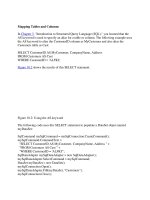
Use of the Arborbolt Lightning Protection Connector on Trees
Generated by Foxit PDF Creator © Foxit Software
For evaluation only.