Tài liệu Hard Disk Drive Servo Systems- P7 pptx
Bạn đang xem bản rút gọn của tài liệu. Xem và tải ngay bản đầy đủ của tài liệu tại đây (216.47 KB, 20 trang )
11
A Benchmark Problem
Before ending this book, we post in this chapter a typical HDD servo control design
problem. The problem has been tackled in the previous chapters using several design
methods, such as PID, RPT, CNF, PTOS and MSC control. We feel that it can serve as
an interesting and excellent benchmark example for testing other linear and nonlinear
control techniques.
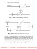
We recall that the complete dynamics model of a Maxtor (Model 51536U3) hard
drive VCM actuator can be depicted as in Figure 11.1:
Nominal plant
Resonance modes
Noise
Figure 11.1. Block diagram of the dynamical model of the hard drive VCM actuator
The nominal plant of the HDD VCM actuator is characterized by the following
second-order system:
sat (11.1)
and
(11.2)
where the control input
is limited within V and is an unknown input dis-
turbance with
mV. For simplicity and for simulation purpose, we assume
that the unknown disturbance
mV. The measurement output available for
Please purchase PDF Split-Merge on www.verypdf.com to remove this watermark.
292 11 A Benchmark Problem
control, i.e. (in
l
um), is the measured displacement of the VCM R/W head and is
given by
Noise (11.3)
where the transfer functions of the resonance modes are given by
(11.4)
with
represents the variation of the resonance modes of the actual
actuators whose resonant dynamics change from time to time and also from disk
to disk in a batch of million drives. Note that many new hard drives in the market
nowadays might have resonance modes at much higher frequencies (such as those
for the IBM microdrives studied in Chapter 9). But, structurewise, they are almost
the same. The output disturbance (in
l
um), which is mainly the repeatable runouts, is
given by
(11.5)
and the measurement noise is assumed to be a zero-mean Gaussian white noise with
a variance
(
l
um) .
The problem is to design a controller such that when it is applied to the VCM
actuator system, the resulting closed-loop system is asymptotically stable and the
actual displacement of the actuator, i.e.
, tracks a reference
l
um. The overall
design has to meet the following specifications:
1. the overshoot of the actual actuator output is less than 5%;
2. the mean of the steady-state error is zero;
3. the gain margin and phase margin of the overall design are, respectively ,greater
than 6 dB and
; and
4. the maximum peaks of the sensitivity and complementary sensitivity functions
are less than 6 dB.
The results of Chapter 6 show that the 5% settling times of our design using the
CNF control technique are, respectively, 0.80 ms in simulation and 0.85 ms in actual
hardware implementation. We note that the simulation result can be further improved
if we do not consider actual hardware constraints in our design. For example, the
Please purchase PDF Split-Merge on www.verypdf.com to remove this watermark.
11 A Benchmark Problem 293
CNF control law given below meets all design specifications and achieves a 5%
settling time of 0.68 ms. It is obtained by using the toolkit of [55] under the option
of the pole-placement method with a damping ratio of
and a natural frequency of
2800 rad/sec together with a diagonal matrix
diag . The
dynamic equation of the control law is given by
sat
(11.6)
(11.7)
where
(11.8)
and
(11.9)
with
being given as in Equation 6.9.
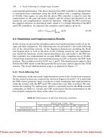
The simulation results obtained with
given in Figures 11.2 to 11.4 show
that all the design specifications have been achieved. In particular, the resulting 5%
settling time is 0.68 ms, the gain margin is 7.85 dB and the phase margin is 44.7
,
and finally, the maximum values of the sensitivity and complementary sensitivity
functions are less than 5 dB. The overall control system can still produce a satisfac-
tory result and satisfy all the design specifications by varying the resonance modes
with the value of
changing from to .
Nonetheless, we invite interested readers to challenge our design. Noting that
for the track-following case, i.e. when
l
um, the control signal is far below its
saturation level. Because of the bandwidth constraint of the overall system, it is not
possible (and not necessary) to utilize the full scale of the control input to the actuator
in the track-following stage. However, in the track-seeking case or equivalently by
setting a larger target reference, say
l
um, the very problem can serve as a
good testbed for control techniques developed for systems with actuator saturation.
Interested readers are referred to Chapter 7 for more information on track seeking of
HDD servo systems.
Please purchase PDF Split-Merge on www.verypdf.com to remove this watermark.
294 11 A Benchmark Problem
0
0.5
1
1.5
2
2.5
3
3.5
4
0
0.2
0.4
0.6
0.8
1
Time (ms)
R/W head displacement (μm)
0
0.5
1
1.5
2
2.5
3
3.5
4
−0.1
−0.05
0
0.05
0.1
0.15
Time (ms)
Control signal to VCM (V)
(a) and for the system without output disturbance and noise
0
0.5
1
1.5
2
2.5
3
3.5
4
0
0.2
0.4
0.6
0.8
1
Time (ms)
R/W head displacement (μm)
0
0.5
1
1.5
2
2.5
3
3.5
4
−0.1
−0.05
0
0.05
0.1
0.15
Time (ms)
Control signal to VCM (V)
(b) and for the system with output disturbance and noise
Figure 11.2. Output responses and control signals of the CNF control system
Please purchase PDF Split-Merge on www.verypdf.com to remove this watermark.
11 A Benchmark Problem 295
10
0
10
1
10
2
10
3
10
4
10
5
−200
−150
−100
−50
0
50
100
150
Magnitude (dB)
Frequency (Hz)
10
0
10
1
10
2
10
3
10
4
10
5
−600
−500
−400
−300
−200
−100
Phase (deg)
Frequency (Hz)
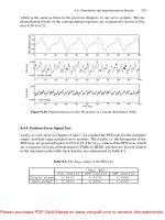
(a) Bode plot
−4.5
−4
−3.5
−3
−2.5
−2
−1.5
−1
−0.5
0
0.5
−3
−2
−1
0
1
2
3
0 dB
−10 dB
−6 dB
−4 dB
−2 dB
10 dB
6 dB
4 dB
2 dB
Real axis
Imaginary axis
(b) Nyquist plot
Figure 11.3. Bode and Nyquist plots of the CNF control system
Please purchase PDF Split-Merge on www.verypdf.com to remove this watermark.
296 11 A Benchmark Problem
10
0
10
1
10
2
10
3
10
4
10
5
−180
−160
−140
−120
−100
−80
−60
−40
−20
0
20
Magnitude (dB)
Frequency (Hz)
Sensitivity function
Complementary sensitivity function
Figure 11.4. Sensitivity and complementary sensitivity functions with the CNF control
Please purchase PDF Split-Merge on www.verypdf.com to remove this watermark.
References
1. Franklin GF, Powell JD, Workman ML. Digital control of dynamic systems. 3rd edn
Reading (MA): Addison-Wesley; 1998.
2. Fujimoto H, Hori Y, Yarnaguchi T, Nakagawa S. Proposal of seeking control of hard
disk drives based on perfect tracking control using multirate feedforward control. Proc
6th Int Workshop Adv Motion Contr; Nagoya, Japan; 2000. p. 74–9.
3. Goh TB, Li Z, Chen BM, Lee TH, Huang T. Design and implementation of a hard disk
drive servo system using robust and perfect tracking approach. IEEE Trans Contr Syst
Technol 2001; 9:221–33.
4. Gu Y, Tomizuka M. Digital redesign and multi-rate control for motion control – a gen-
eral approach and application to hard disk drive servo system. Proc 6th Int Workshop
Adv Motion Contr; Nagoya, Japan; 2000. p. 246–51.
5. Hara S, Hara T, Yi L, Tomizuka M. Two degree-of-freedom controllers for hard disk
drives with novel reference signal generation. Proc American Contr Conf; San Diego,
CA; 1999. p. 4132–6.
6. Huang Y, Messner WC, Steele J. Feed-forward algorithms for time-optimal settling of
hard disk drive servo systems. Proc 23rd Int Conf Ind Electron Contr Instrum; New
Orleans, LA; 1997. p. 52–7.
7. Ho HT. Fast bang-bang servo control. IEEE Trans Magn 1997; 33:4522–7.
8. Ishikawa J, Tomizuka M. A novel add-on compensator for cancellation of pivot nonlin-
earities in hard disk drives. IEEE Trans on Magn 1998; 34:1895–7.
9. Iwashiro M, Yatsu M, Suzuki H. Time optimal track-to-track seek control by model
following deadbeat control. IEEE Trans Magn 1999; 35:904–9.
10. Pao LY, Franklin GF. Proximate time-optimal control of third-order servomechanisms.
IEEE Trans Automat Contr 1993; 38:560–80.
11. Patten WN, Wu HC, White L. A minimum time seek controller for a disk drive. IEEE
Trans Magn 1995; 31:2380–7.
12. Takakura S. Design of a tracking system using
-delay two-degree-of-freedom control
and its application to hard disk drives. Proc 1999 IEEE Int Conf Contr Appl; Kohala
Coast, HI; 1999. p. 170–5.
13. Wang L, Yuan L, Chen BM, Lee TH. Modeling and control of a dual actuator servo
system for hard disk drives. Proc 1998 Int Conf Mechatron Technol; Hsinchu, Taiwan;
1998. p. 533–8.
14. Weerasooriya S, Low TS, Mamun AA. Design of a time optimal variable structure con-
troller for a disk drive actuator. Proc Int Conf Ind Electron Contr Instrum; Hawaii; 1993.
p. 2161–5.
Please purchase PDF Split-Merge on www.verypdf.com to remove this watermark.
298 References
15. Yamaguchi T, Soyama Y, Hosokawa H, Tsuneta K, Hirai H. Improvement of settling
response of disk drive head positioning servo using mode switching control with initial
value compensation. IEEE Trans Magn 1996; 32:1767–72.
16. Zhang DQ, Guo GX. Discrete-time sliding mode proximate time optimal seek control
of hard disk drives. IEE Proc Contr Theory Appl 2000; 147:440–6.
17. Chang JK, Ho HT. LQG/LTR frequency loop shaping to improve TMR budget. IEEE
Trans Magn 1999; 35:2280–82.
18. Hanselmann H, Engelke A. LQG-control of a highly resonant disk drive head position-
ing actuator. IEEE Trans Ind Electron 1988; 35:100–4.
19. Weerasooriya S, Phan DT. Discrete-time LQG/LTR design and modeling of a disk drive
actuator tracking servo system. IEEE Trans Ind Electron 1995; 42:240–7.
20. Chen BM, Lee TH, Hang CC, Guo Y, Weerasooriya S. An
almost disturbance
decoupling robust controller design for a piezoelectric bimorph actuator with hysteresis.
IEEE Trans Contr Syst Technol 1997; 7:160–74.
21. Hirata M, Atsumi T, Murase A, Nonami K. Following control of a hard disk drive by
using sampled-data
control. Proc 1999 IEEE Int Conf Contr Appl; Kohala Coast,
HI; 1999. p. 182-6.
22. Li Y, Tomizuka M. Two degree-of-freedom control with adaptive robust control for hard
disk servo systems. IEEE/ASME Trans Mechatron 1999; 4:17–24.
23. Hirata M, Liu KZ, Mita T, Yamaguchi T. Head positioning control of a hard disk drive
using
theory. Proc 31st IEEE Conf Dec Contr; Tucson, AZ; 1992. p. 2460–1.
24. Kim BK, Chung WK, Lee HS, Choi HT, Suh IH, Chang YH. Robust time optimal
controller design for hard disk drives. IEEE Trans Magn 1999; 35:3598–607.
25. Teo YT, Tay TT. Application of the
optimal regulation strategy to a hard disk servo
system. IEEE Trans Contr Syst Technol 1996; 4:467–72.
26. Du CL, Xie LH, Teoh JN, Guo GX. An improved mixed
control design for
hard disk drives. IEEE Trans Contr Syst Technol 2005; 13:832–9.
27. Chen R, Guo G, Huang T, Low TS. Adaptive multirate control for embedded HDD
servo systems. Proc 24th Int Conf Ind Electron Contr Instrum; Aachen, Germany; 1998.
p. 1716–20.
28. McCormick J, Horowitz R. A direct adaptive control scheme for disk file servos. Proc
1993 American Contr Conf; San Francisco, CA; 1993. p. 346–51.
29. Weerasooriya S, Low TS. Adaptive sliding mode control of a disk drive actuator. Proc
Asia-Pacific Workshop Adv Motion Contr; Singapore, 1993. p. 177–82.
30. Workman ML. Adaptive proximate time optimal servomechanisms [PhD diss]. Stanford
University; 1987.
31. Internet websites: www.storagereview.com; www.pcguide.com; www.storage.ibm.com;
www.mkdata.dk; 2001.
32. Porter J. Disk drives’ evolution. Presented at 100th Ann Conf Magn Rec Info Stor; Santa
Clara, CA; 1998.
33. Mamun AA. Servo engineering. Lecture Notes; Dept of Electrical & Computer Engi-
neering, National University of Singapore; 2000.
34. Zhang JL. Electronic computer magnetic storing devices. Beijing: Military Industry
Publishing House; 1981 (in Chinese).
35. Li Q, Hong OE, Hui Z, Mannan MA, Weerasooriya S, Ann MY, Chen SX, Wood R.
Analysis of the dynamics of 3.5
hard disk drive actuators. Technical Report. Data
Storage Institute (Singapore); 1997.
36. Chang JK, Weerasooriya S, Ho HT. Improved TMR through a frequency shaped servo
design. Proc 23rd Int Conf Ind Electron Contr Instrum; New Orleans, LA; 1997. p. 47–
51.
Please purchase PDF Split-Merge on www.verypdf.com to remove this watermark.