Tài liệu 2D Artwork and 3D Modeling for Game Artists- P3 doc
Bạn đang xem bản rút gọn của tài liệu. Xem và tải ngay bản đầy đủ của tài liệu tại đây (3.35 MB, 50 trang )
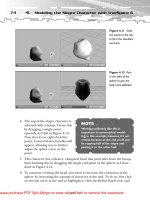
6. The top of the slogre character is
adorned with a hump. Create this
by dragging a single point
upwards, as I did in Figure 4.13.
Note that if you right-click this
point, Control Vertex handles will
appear, allowing you to further
adjust the spline curve at this
point.
7. This character has a bizarre, elongated head that protrudes from the hump.
Start forming this by dragging the single end point of the sphere as I have
done in Figure 4.14.
8. To continue creating the head, you need to increase the resolution of the
sphere by increasing the amount of isocurves at the end. To do so, first click
on the last curve at the end to highlight it, click the Refine Patch tool, and
74
4.
Modeling the Slogre Character with trueSpace 6
Figure 4.11 Scale
two points at the top
to form the shoulders
and back.
Figure 4.12 Push
in the sides of the
sphere to give the
body more definition.
NOTE
Working uniformly like this is
important to symmetrical model-
ing; in this example, however, it’s not
critical because at the end you’ll just
be copying half of the slogre and
pasting it to the other half.
TEAMFLY
Team-Fly
®
Please purchase PDF Split-Merge on www.verypdf.com to remove this watermark.
click and drag along the length of the body (you’ll see an orange curve, as
shown in Figure 4.15). When you reach the spot where want to place the
curve, release the mouse button. You can continue to add curves by left-
clicking; for now, however, just right-click to deselect this tool.
75
Modeling the Slogre
Figure 4.13 Drag
a single point at top
to form the hump.
Figure 4.15
Create a new
isocurve on the head
using the Refine
Patch tool.
Figure 4.14 Start
forming the head by
dragging the top end
point of the sphere.
Please purchase PDF Split-Merge on www.verypdf.com to remove this watermark.
9. Pinch in two points on either side of the newly created isocurve to further
define the head. To do so, Ctrl+click one on each side, then scale them
slightly (see Figure 4.16).
10. To increase the hump’s definition, making it more pronounced, right-click
one of the top points of the hump to bring up the control handles, and click
and drag the handles to change the sharpness at that point (see Figure 4.17).
76
4.
Modeling the Slogre Character with trueSpace 6
TIP
If you’re having trouble switching back and forth between
operating on a single point or entire curve, just click the
Object tool (white arrow), then right-click the NURBS
object to re-enter the edit mode.Then just select the Patch
Edit tool of choice to continue modeling.
Figure 4.16
Pinch the head a bit
to further define it.
Figure 4.17
Sharpen the hump
by adjusting the con-
trol handles of a
point on top.
Please purchase PDF Split-Merge on www.verypdf.com to remove this watermark.
11. To extend the head even further, Ctrl+click both the last isocurve and the
end point of the head and drag to stretch it. The results are shown in
Figure 4.18 (I also rotated and scaled that last curve a bit).
12. Continue refining the head using the Refine Patch tool to create new curves,
and move/rotate/scale them, as well as the end point, as I have done in
Figure 4.19.
13. Once you’re satisfied with the head, continue making small curve and point
adjustments around the body in the same manner until the body is how you
want it to be (see Figure 4.20). You don’t have to go nuts adding isocurves;
only a few make the body very smooth.
14. When finished, exit editing mode by clicking the Object tool.
15. Save this piece by clicking File, Save As, Object, and name it body.cob.
(You’ll need to recall it at the end so you can attach the other pieces.)
77
Modeling the Slogre
Figure 4.18 Pull
the end of the head
out further.
Figure 4.19 Add
and adjust more
isocurves to continue
refining the head.
Please purchase PDF Split-Merge on www.verypdf.com to remove this watermark.
Step 2: Build the Leg
You’ll build this next piece using the Draw Panel tool to explore some other
NURBS modeling techniques that trueSpace has to offer. Draw Panel enables you
to draw a simple spline curve and then extrude it—only in this case, the extrusion
becomes a NURBS object. You’ll start by making the basic foot pattern, and pull
the entire leg right out of it!
1. To use the Draw Panel tool, you must turn on 3D Controls in the Preferences
panel. To do so, choose File, Preferences, and select the 3D Controls option
in the dialog box that appears (see Figure 4.21).
2. Click on the Draw Panel tool, located in the toolbar at the bottom of the
screen.
3. To add a panel to the screen, click and drag in the main Perspective view as
I have in Figure 4.22. This panel will enable you to draw a 2D spline curve
and extrude it. Notice that when you add the panel, an entire suite of tools
pops up as well; these offer a multitude of ways in which you can draw curves
on the panel.
78
4.
Modeling the Slogre Character with trueSpace 6
Figure 4.20
Continue manipulat-
ing the rest of the
body’s curves and
points to reach the
shape you desire.
Figure 4.21
Enable the 3D
Controls option for
this next exercise.
Please purchase PDF Split-Merge on www.verypdf.com to remove this watermark.
4. Choose the Add Curve tool and create a
foot-shaped pattern, as shown in Figure
4.23; when you reach the start point of the
curve, right-click to close the shape. (The
shape of the foot doesn’t have to be
perfect; you’ll adjust it in the next step.)
79
Modeling the Slogre
Figure 4.22 Click
on the Draw Panel
tool and add a panel
to the scene.
The Draw
Panel tool
NOTE
You can switch to a top
orthogonal view above the
panel by clicking one of the
panel’s corner points.
Figure 4.23 Add a
foot-shaped pattern
to the panel using
the Add Curve tool.
Use the slogre sketch
as a reference.
Please purchase PDF Split-Merge on www.verypdf.com to remove this watermark.
5. Once the general shape has been created, click on any of the curve points to
display its control handles, and use these handles to adjust the shape of the
curve at that point—as well as to drag those points to new locations (see
Figure 4.24). You can also add and delete points using any of the various
vertex-edit tools that accompany this operation.
6. When you’re satisfied with your shape, right-click anywhere outside the panel
to exit, or click the Object tool. Another small set of tools appears; these
enable you to extrude your shape. Click the Extrude tool to display a double-
ended control handle, perpendicular to the face of your shape, and then
click and drag on the endpoint of one handle to extrude the base of the foot
slightly as I have done in Figure 4.25.
7. When the base of your foot is created, right-click to exit extrusion mode.
The object you just created is now a modifiable NURBS object, just like the
slogre’s body you created earlier. The only difference here is that both ends
are open and faceless (don’t worry about that for now; you’ll cap the bottom
80
4.
Modeling the Slogre Character with trueSpace 6
Figure 4.24 Adjust
the shape of the foot
using the control
handles of the points.
Figure 4.25 Use
the Extrude tool to
sweep the face of the
foot into 3D.
Please purchase PDF Split-Merge on www.verypdf.com to remove this watermark.
later). To begin shaping the foot, use the Refine Patch tool to add an
isocurve as you did with the slogre’s body. In Figure 4.26, I created a couple
new curves and scaled them to form the foot.
8. For each time you want to extrude your shape vertically, remember to first
create an isocurve, and then pull the last curve upward. When the general
shape of the foot is done, use the Delete Row of Points tool (opposite the
Refine Patch tool) to remove unnecessary curves. Remember, the more
curves you have, the higher the number of polygons in the resultant model.
Figure 4.27 shows my slogre foot after I killed several superfluous curves.
9. When you’re satisfied with the foot, right-click the last, top curve to edit the
points along the edge. Move these points into a circular ankle shape. Then,
continue adding isocurves and extruding the ankle portion of the leg (see
Figure 4.28).
81
Modeling the Slogre
Figure 4.26 Add
new isocurves to the
foot object and move
and scale them to
shape it.
Figure 4.27
Remove unnecessary
curves using the
Delete Row of Points
tool.
Please purchase PDF Split-Merge on www.verypdf.com to remove this watermark.
10. Continue extruding the rest of the leg, forming a calf muscle and thigh by
scaling and shifting the isocurves at those locations. If the points from the
foot made indentations along the leg at any point, simply select the individ-
ual points and reposition them. The NURBS properties of the object make
things sweet and smooth (see Figure 4.29).
11. When you’re finished extruding the leg and are satisfied, save this object as
leg.cob so you can retrieve it later.
82
4.
Modeling the Slogre Character with trueSpace 6
Figure 4.28 Move
the points at the top
into a circular shape
for the leg, and con-
tinue extruding.
Figure 4.29
Continue pulling out
the rest of the leg,
making adjustments
to form the calf and
thigh.
Step 3: Build the Arm
You could create the arm just as you did the leg, but the arm is a lot more compli-
cated—especially around the hand. For this operation, then, it’s best to use plain
old point editing to build and sweep the arm. This doesn’t mean a whole lot as far
as the resulting model is concerned; in fact, the polygon count will be much lower.
The arm will suffer in its organic-ness, however, because point editing has nothing
Please purchase PDF Split-Merge on www.verypdf.com to remove this watermark.
on NURBS objects when it comes to creating realistic organic shapes. When you
bring the model into 3D Studio Max and smooth it out, however, you really won’t
be able to tell the difference. I think the most noticeable difference between point-
edit modeling and NURBS modeling is the speed. In the time it will take to model
this one arm, I could finish the body and leg portions twice over!
1. Let’s start with the wrist area of the slogre. If you refer to the slogre sketch,
you’ll notice that he’s wearing slave-like bands with sharp, pointed studs.
Create a band by adding a 10-sided cylinder primitive to the scene and scal-
ing it down to size, as shown in Figure 4.30. (The cylinder primitive is also
located in the toolbar at the bottom of the screen.)
2. To create the pointed studs, first right-click the cylinder to enter point-edit
mode. (This is the same as NURBS mode, but without the NURBS isocurve
functionality.)
3. Using the Point Edit: Faces tool, click on a face to select it, and pull it quickly
to a tip using the Tip tool. Repeat this process for every other face (see
Figure 4.31).
4. The tips of the spikes are too long—use the Point Edit: Vertices tool to select
each tip’s point while you hold down the Ctrl key. When all points are
selected, scale them down to size (see Figure 4.32).
83
Modeling the Slogre
Figure 4.30
Start the arm off
with a 10-sided
cylinder primitive.
Please purchase PDF Split-Merge on www.verypdf.com to remove this watermark.
5. To create the rest of the arm, select the top face of the cylinder and use the
Sweep tool to extrude it. Continue sweeping this face, scaling each time,
until you get a general shape of the arm. Remember to use the slogre sketch
as a guide—his arms are massive with huge, bulging biceps. Just like mine.
84
4.
Modeling the Slogre Character with trueSpace 6
Figure 4.31 Select
every other face of
the cylinder and
apply the Tip tool.
Figure 4.32 Select
all the tips and scale
them down.
Figure 4.33 Use
the Sweep tool
repeatedly to extrude
the top face of the
cylinder into the
entire arm.
TEAMFLY
Team-Fly
®
Please purchase PDF Split-Merge on www.verypdf.com to remove this watermark.
6. Make minor adjustments to the arm by selecting a face or multiple faces (by
holding down Ctrl and clicking) and moving/scaling them appropriately. In
Figure 4.34, I’m selecting a patch of the bicep area and augmenting it.
7. Now for the hand—just as you did with the arm, select the face on the other
side of the cuff and sweep it several times, adjusting the width to conform to
a hand shape as I have done in Figure 4.35.
8. Select a pad of faces on the inside of the hand and move, rotate, and/or
scale them to make a palm (see Figure 4.36).
9. When the palm portion of your hand is complete, start adding fingers by first
breaking the end face into four smaller sections. To do so, use the Add Edges
tool (part of the tool group that pops up when you enter point-edit mode) to
create an edge between opposite vertices on the face (see Figure 4.37).
10. The fingers can’t just be extruded from these new faces you’ve just created.
Instead, select each face and apply the Bevel tool (Figure 4.38).
85
Modeling the Slogre
Figure 4.34
Enhance the muscles
of the arm by select-
ing faces and moving
or scaling them to
size.
Figure 4.35 Begin
sweeping the hand
on the other side of
the cuff.
Please purchase PDF Split-Merge on www.verypdf.com to remove this watermark.
11. With the new bevels in place, the fingers can be pulled out of them.
However, the faces are too square for my standards—use the Add Vertex tool
to add four new vertices to the edges of each face, and move each new vertex
away from the center to round it out. When you’re finished with each face,
create the fingers by using the Sweep tool on each (see Figure 4.39).
86
4.
Modeling the Slogre Character with trueSpace 6
Figure 4.36 Form
the palm of the hand
by manipulating a
small set of faces.
Figure 4.37 Start
the fingers by creat-
ing new edges at the
end of the palm.
Figure 4.38 Bevel
the new faces so you
can add the fingers.
Please purchase PDF Split-Merge on www.verypdf.com to remove this watermark.
12. Continue sweeping the faces of each finger, scaling them as you get closer to
the tip. In Figure 4.40, I also moved the faces away from each other so that
from a short distance, a player can discern each individual finger.
13. To form the long, slashing nails that embellish your behemoth, add a small
edge at the tip of each finger, effectively creating a triangular face, and use
the Tip tool to pull that out. Then, grab the tip and pull it out further—the
nails should be long, according to the sketch, about the length of the entire
hand (see Figure 4.41).
14. Form the thumb the same way you created the fingers in steps 11, 12, and
13—though there’s no need to bevel the first face. Make the thumb curve
outward slightly so it can hold the RF-9 plasma gun (see Figure 4.42).
That’s it for the arm. Notice that this took much longer than the other body parts,
but the tradeoff is in the face count–to-smoothness ratio. In Figure 4.43, my arm
model shows only 341 faces, even with all of the minute detail, whereas the leg
object was more than 600; that said, the leg looks much more organic and realistic
87
Modeling the Slogre
Figure 4.39 Add
vertices to the square
faces and round
them out. Sweep
them to start the fin-
gers.
Figure 4.40
Continue sweeping
the faces to form the
fingers.
Please purchase PDF Split-Merge on www.verypdf.com to remove this watermark.
than this arm. (You’ll fix the choppiness in 3D Studio using a Smooth modifier—
more on that in Chapter 6, “ U-V Mapping the Slogre with DeepUV,” when you
import the slogre model and prepare to unwrap the U-V coordinates.) For now,
save this object as arm.cob.
Step 4: Complete the Model
(Well, Half of It)
Now it’s time to bring the fruits of your labor together into a working slogre
model. There are a number of ways to finish up a model, but I think the best way
to handle this one is to create only half of it since this beast is basically symmetrical.
If you were to union the legs and arms to both sides of the object and then opti-
mize it in 3D Studio Max, however, the mesh would be smooth but the polygons
would be a jumbled mess—that is, the optimization process in Max would make
the mesh uneven throughout the character’s body. Instead, let’s union one arm
and one leg to the body, slice the sucker in half, and let Max take care of the rest,
since its suite of optimization tools is far more advanced.
88
4.
Modeling the Slogre Character with trueSpace 6
Figure 4.41 Form
the nails by adding
small edges to the
fingertips and tipping
them.
Figure 4.42
Create the thumb
using the same steps
as you did with the
other fingers.
Please purchase PDF Split-Merge on www.verypdf.com to remove this watermark.
To load into one scene the three separate body components that you created in
previous sections, start a new scene and choose File, Load, Object to load each
component individually. (If you like, you can load my components instead of the
ones you created by choosing the arm.cob, leg.cob, and body.cob files from the
Chapter 4 Data section on the CD-ROM.) Once these components are loaded, the
scene should consist of two NURBS objects (the body and leg) and a regular poly-
hedron object (the arm). Your job is to align the ends of the appendages to the
body and Boolean Union them together. First, however, you need to resize the
body parts and adjust the NURBS resolution.
1. Click on the body object to select it, and then right-click on the NURBS
Patch to Polyhedron tool to bring up the
Patch Options panel. I have the Static
Res set to 0.3, which will result in the
body object having just over 1,100 faces.
Click on the Patch to Polyhedron tool
to permanently convert the body to a
regular mesh (see Figure 4.44).
89
Modeling the Slogre
Figure 4.43 The
completed arm.
Notice the low poly-
gon count and high
detail, but sacrifice in
smoothness.
TIP
When you convert a NURBS
object to a regular polygon,
the operation is not undoable!
Be sure to save your work
before performing this action!
Please purchase PDF Split-Merge on www.verypdf.com to remove this watermark.
2. Repeat step 1 for the leg object, only set its Static Res to 0.2. This will make
it contain just over 600 polygons.
3. After the leg object is converted, scale it evenly so its proportion is accurate
when placed next to the slogre’s body, and rotate it into position where it
should protrude.
4. Repeat step 3 for the arm object (it doesn’t need to be converted; you built
it from an existing polyhedron mesh). Figure 4.45 shows my arrangement.
5. Make sure the arm and leg objects extend fully into the body of the slogre,
or you’ll get holes in the final mesh. To do so, rotate around the body and
zoom in close to be sure they’re all the way in. (If you have your rendering
environment set to Solid mode you can see the mesh move in and out of one
another much more easily.)
6. When you’re satisfied that the appendages are, indeed, all the way in, save
your scene, and use the Object Union tool to fuse the three body parts
together.
90
4.
Modeling the Slogre Character with trueSpace 6
Figure 4.44 Use
the Convert Patch to
Polyhedron tool to
turn the NURBS
object into an ordi-
nary mesh.
Figure 4.45
Convert the NURBS
leg, and scale and
position it— and the
arm— on the body.
Please purchase PDF Split-Merge on www.verypdf.com to remove this watermark.
7. If the union operation was successful, you should have one solid, goofy-
looking mesh with a single arm and leg sticking out of it; the next step is to
split the slogre’s body in half. To begin, create a cube primitive in the scene
and scale it so it’s much bigger than the slogre itself.
8. Position the cube so it intersects the half of the body that has no arm or leg
(see Figure 4.47). Be sure that the edge of the cube is as close as possible to
the middle seam of the body.
9. Select the slogre mesh, click the Object
Subtraction tool, and click the cube.
You should end up with a half mesh.
91
Modeling the Slogre
Figure 4.46 Fuse
the arm and leg to
the body using the
Object Union tool.
NOTE
Should trueSpace proclaim that an error has occurred, right-
click on the Object Union tool to bring up a Booleans options
panel (see Figure 4.46). In this panel, you can adjust the Identity
value and try the union operation again.This value represents a
distance in 1/100ths of a millimeter between near coincident
vertices—that is, vertices that happen to be on top of one
another. Adjusting this value will tell trueSpace to recalculate
the operation and try to avoid invalid geometric fusion.
NOTE
If trueSpace issued a warning,
right-click the tool and change
the Identity value a bit, and
then try again.
Please purchase PDF Split-Merge on www.verypdf.com to remove this watermark.
10. Rotate around to the foot. When you created the leg, the foot was extruded
from a spline curve and had no end cap; notice that in solid-render mode, it
appears open. To fix this, right-click on the mesh to enter point-edit mode,
choose the Point Edit: Add Face tool, and click on this open area to close it
up (see Figure 4.48).
11. Rotate around to the flat side of the slogre, where it was cut; as a result of
the Boolean operation, there’s a solid face there. For you to be able to fuse
a copy of the finished side of the slogre to the other side, the slogre mesh
needs to be a hollow object. To make it so, select the Point Edit: Delete
Face tool and click once on the abovementioned flat area to remove it (see
Figure 4.49). As soon as you delete the face, right-click to deselect the Delete
Face tool.
92
4.
Modeling the Slogre Character with trueSpace 6
Figure 4.47 Add a
cube primitive to the
scene, scale it, and
position it so it covers
the entire half of the
slogre’s mesh.
Figure 4.48
Subtract the cube
object from the slo-
gre, and cap the hole
on the foot using the
Add Face tool.
Please purchase PDF Split-Merge on www.verypdf.com to remove this watermark.
Export the Mesh
You’re finished with your half-shell slogre mesh and are ready to save it as an STL
file and bring it over to Max for completion and U-V mapping, just as you did with
the RF-9 plasma gun. To do so, choose File, Save As, Object; from the Save As Type
list, select Stereolithography (*.STL). To finalize the slogre mesh and continue
mapping, move on to Chapter 6.
Summary
In this chapter you learned how to create a character mesh object using new and
powerful NURBS modeling techniques that allow your creation to look very realis-
tic, with a more natural, organic feel. There are pros and cons to using NURBS; on
the positive side the resulting model can be created in only a fraction of the time it
would take using older modeling techniques such as shaping with primitives and
point editing. The negative side is the resulting polygon count, which, for now, can
be fairly high. However, with the steadily evolving computing technology, the need
to be keenly aware of polygon counts in models will no doubt diminish.
93
Summary
Figure 4.49
Delete the flat, cut
surface from the side
of the slogre’s body
with the Delete Face
tool.
Please purchase PDF Split-Merge on www.verypdf.com to remove this watermark.