Tài liệu GPS - đường dẫn quán tính và hội nhập P8 pptx
Bạn đang xem bản rút gọn của tài liệu. Xem và tải ngay bản đầy đủ của tài liệu tại đây (395.95 KB, 26 trang )
9
Differential GPS
9.1 INTRODUCTION
Differential GPS (DGPS) is a technique for reducing the error in GPS-derived
positions by using additional data from a reference GPS receiver at a known
position. The most common form of DGPS involves determining the combined
effects of navigation message ephemeris and satellite clock errors [including the
effects of selective availability (SA), if active] at a reference station and transmitting
pseudorange corrections, in real time, to a user's receiver. The receiver applies the
corrections in the process of determining its position [63]. This results in the
following:
Some error sources are canceled completely:
(a) selective availability and
(b) satellite ephemeris and clock errors.
With other error sources, cancelation degrades with distance:
(a) ionospheric delay error and
(b) tropospheric delay error.
Still other error sources are not canceled at all:
(a) multipath errors and
(b) receiver errors.
265
Global Positioning Systems, Inertial Navigation, and Integration,
Mohinder S. Grewal, Lawrence R. Weill, Angus P. Andrews
Copyright # 2001 John Wiley & Sons, Inc.
Print ISBN 0-471-35032-X Electronic ISBN 0-471-20071-9
9.2 LADGPS, WADGPS, AND WAAS
9.2.1 Description of Local-Area DGPS (LADGPS)
LADGPS is a form of DGPS in which the user's GPS receiver receives real-time
pseudorange and, possibly, carrier phase corrections from a reference receiver
generally located within the line of sight. The corrections account for the combined
effects of navigation message ephemeris and satellite clock errors (including the
effects of SA) and, usually, atmospheric propagation delay errors at the reference
station. With the assumption that these errors are also common to the measurements
made by the user's receiver, the application of the corrections will result in more
accurate coordinates [81].
9.2.2 Description of Wide-Area DGPS (WADGPS)
WADGPS is a form of DGPS in which the user's GPS receiver receives corrections
determined from a network of reference stations distributed over a wide geographical
area. Separate corrections are usually determined for speci®c error sources, such as
satellite clock, ionospheric propagation delay, and ephemeris. The corrections are
applied in the user's receiver or attached computer in computing the receiver's
coordinates. The corrections are typically supplied in real time by way of a
geostationary communications satellite or through a network of ground-based
transmitters. Corrections may also be provided at a later date for post-processing
collected data [81].
9.2.3 Description of Wide Area Augmentation System (WAAS)
WAAS enhances the GPS SPS and is available over a wide geographical area. The
WAAS being developed by the Federal Aviation Administration, together with other
agencies, will provide WADGPS corrections, additional ranging signals from
geostationary (GEO) satellites, and integrity data on the GPS and GEO satellites
[81].
The GEO Uplink Subsytem includes a closed-loop control algorithm and special
signal generator hardware. These ensure that the downlink signal to the users is
controlled adequately to be used as a ranging source to supplement the GPS satellites
in view.
The primary mission of WAAS is to provide a means for air navigation for all
phases of ¯ight in the National Airspace System (NAS) from departure, en route,
arrival, and through approach. GPS augmented by WAAS offers the capability for
both nonprecision approach (NPA) and precision approach (PA) within a speci®c
service volume. A secondary mission of the WAAS is to provide a WAAS network
time (WNT) offset between the WNT and Coordinated Universal Time (UTC) for
nonnavigation users.
WAAS provides improved en route navigation and PA capability to WAAS
certi®ed avionics. The safety critical WAAS system consists of the equipment and
266
DIFFERENTIAL GPS
software necessary to augment the Department of Defense (DoD) provided GPS
SPS. WAAS provides a signal in space (SIS) to WAAS certi®ed aircraft avionics
using the WAAS for any FAA-approved phase of ¯ight. The SIS provides two
services: (1) data on GPS and GEO satellites and (2) a ranging capability.
The GPS satellite data is received and processed at widely dispersed wide-area
reference Stations (WRSs), which are strategically located to provide coverage over
the required WAAS service volume. Data is forwarded to wide-area master stations
(WMSs), which process the data from multiple WRSs to determine the integrity,
differential corrections, and residual errors for each monitored satellite and for each
predetermined ionospheric grid point (IGP). Multiple WMSs are provided to
eliminate single-point failures within the WAAS network. Information from all
WMSs is sent to each GEO uplink subsystem (GUS) and uplinked along with the
GEO navigation message to GEO satellites. The GEO satellites downlink this data to
the users via the GPS SPS L-band ranging signal (L
1
) frequency with GPS-type
modulation. Each ground-based station=subsystem communicates via a terrestrial
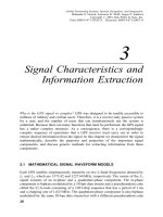
communications subsystem (TCS). See Fig. 9.1.
In addition to providing augmented GPS data to the users, WAAS veri®es its own
integrity and takes any necessary action to ensure that the system meets the WAAS
performance requirements. WAAS also has a system operation and maintenance
function that provides status and related maintenance information to FAA airway
facilities (AFs) NAS personnel.
WAAS has a functional veri®cation system (FVS) that is used for early
development test and evaluation (DT&E), re®nement of contractor site installation
procedures, system-level testing, WAAS operational testing, and long-term support
for WAAS.
GPS satellites
User’s WAAS
receiver
GEO subsystem
Wide-area
master station
Wide-area
reference station-n
Wide-area
reference station-1
GEO uplink
subsystem
Fig. 9.1 WAAS Top Level View
9.2 LADGPS, WADGPS, AND WAAS
267
Correction and Veri®cation (C&V) processes data from all WRSs to determine
integrity, differential corrections, satellite orbits, and residual error bounds for each
monitored satellite. It also determines ionospheric vertical delays and their residual
error bounds at each of the IGPs. C&V schedules and formats WAAS messages and
forwards them to the GUSs for broadcast to the GEO satellites.
C&V's capabilities are as follows:
1. Control C&V Operations and Maintenance (COM) supports the transfer of
®les, performs remotely initiated software con®guration checks, and accepts
requests to start and stop execution of the C&V application software.
2. Control C&V Modes (CMD) manage mode transitions in the C&V subsys-
tem while the application software is running.
3. Monitor C&V (MCV) reports line replaceable unit (LRU) faults and
con®guration status. In addition, it monitors software processes and provides
performance data for the local C&V subsystems.
4. Process Input Data (PID) selects and monitors data from the wide-area
reference equipment (WREs). Data that passes PID screening is repackaged
for other C&V capabilities. PID performs clock and L
1
GPS Precision
Positioning Service L-band ranging signal (L
2
) receiver bias calculations,
cycle slip detection, outlier detection, data smoothing, and data monitoring.
In addition, PID calculates and applies the windup correction to the carrier
phase, accumulates data to estimate the pseudorange to carrier phase bias,
and computes the ionosphere corrected carrier phase and measured slant
delay.
5. Satellite Orbit Determination (SOD) determines the GPS and GEO satellite
orbits and clock offsets, WRE receiver clock offsets, and troposphere delay.
6. Ionosphere Correction Computation (ICC) determines the L
1
IGP vertical
delays, grid ionosphere vertical error (GIVE) for all de®ned IGPs, and L
1
±L
2
interfrequency bias for each satellite transmitter and each WRS receiver.
7. Satellite Correction Processing (SCP) determines the fast and long-term
satellite corrections, including the user differential range error (UDRE). It
determines the WNTand the GEO and WNTclock steering commands [99].
8. Independent Data Veri®cation (IDV) compares satellite corrections, GEO
navigation data, and ionospheric corrections from two independent computa-
tional sources, and if the comparisons are within limits, one source is selected
from which to build the WAAS messages. If the comparisons are not within
limits, various responses may occur, depending on the data being compared,
all the way from alarms being generated to the C&V being faulted.
9. Message Output Processing (MOP) transmits messages containing indepen-
dently veri®ed results of C&V calculations to the GUS processing (GP) for
broadcast.
10. C&V Playback (PLB) processes the playback data that has been recorded by
the other C&V capabilities.
268
DIFFERENTIAL GPS
11. Integrity Data Monitoring (IDM) checks both the broadcast and the to-be-
broadcast UDREs and GIVEs to ensure that they are properly bounding their
errors. In addition, it monitors and validates that the broadcast messages are
sent correctly. It also performs the WAAS time-to-alarm validation
[1, 99].
9.2.3.1 WRS Algorithms Each WRS collects raw pseudorange (PR) and
accumulated delta range (ADR) measurements from GPS and GEO satellites
selected for tracking. Each WRS performs smoothing on the measurements and
corrects for atmospheric effects, that is, ionospheric and tropospheric delays. These
smoothed and atmospherically corrected measurements are provided to the WMS.
9.2.3.2 WMS Foreground (Fast) Algorithms The WMS foreground algo-
rithms are applicable to real-time processing functions, speci®cally the computation
of fast correction, determination of satellite integrity status and WAAS message
formatting. This processing is done at a 1-HZ rate.
9.2.3.3 WMS Background (Slow) Algorithms The WMS background
processing consists of algorithms that estimate slowly varying parameters. These
algorithms consist of WRS clock error estimation, grid ionospeci®c delay computa-
tion, broadcast ephemeris computation, satellite orbit determination, satellite ephe-
meris error computation, and satellite visibility computation.
9.2.3.4 Independent Data Veri®cation and Validation Algorithms This
includes a set of WRS and at least one WMS, which enable monitoring the integrity
status of GPS and the determination of wide-area DGPS correction data. Each WRS
has three dual frequency GPS receivers to provide parallel sets of measurement data.
The presence of parallel data streams enables Independent Data Veri®cation and
Validation (IDV&V) to be employed to ensure the integrity of GPS data and their
corrections in the WAAS messages broadcast via one or more GEOs. With IDV&V
active, the WMS applies the corrections computed from one stream to the data from
the other stream to provide veri®cation of the corrections prior to transmission. The
primary data stream is also used for the validation phase to check the active (already
broadcast) correction and to monitor their SIS performance. These algorithms are
continually being improved. The latest versions can be found in references [48, 96,
97, 137, 99] and [98, pp. 397±425].
9.3 GEO UPLINK SUBSYSTEM (GUS)
Corrections from the WMS are sent to the ground uplink subsystem (GUS) for
uplink to the GEO. The GUS receives integrity and correction data and WAAS
speci®c messages from the WMS, adds forward error correction (FEC) encoding,
and transmits the messages via a C-band uplink to the GEO satellites for broadcast
to the WAAS user. The GUS signal uses the GPS standard positioning service
9.3 GEO UPLINK SUBSYSTEM(GUS)
269
waveform (C=A-code, BPSK modulation); however, the data rate is higher (250
bps). The 250 bps of data are encoded with a one-half rate convolutional code,
resulting in a 500-symbols=s transmission rate.
Each symbol is modulated by the C=A-code, a 1:023 Â 10
6
-chips=s pseudo
random sequence to provide a spread-spectrum signal. This signal is then BPSK
modulated by the GUS onto an IF carrier, upconverted to a C-band frequency, and
uplinked to the GEO. It is the C=A-code modulation that provides the ranging
capability if its phase is properly controlled.
Control of the carrier frequency and phase is also required to eliminate uplink
Doppler and to maintain coherence between code and carrier. The GUS monitors the
C-band and L
1
downlinks from the GEO to provide closed-loop control of the PRN
code and L
1
carrier coherency. WAAS short- and long-term code carrier coherence
requirements are met.
9.3.1 Description of the GUS Algorithm
The GUS control loop algorithm ``precorrects'' the code phase, carrier phase, and
carrier frequency of the GEO uplink signal to maintain GEO broadcast code±carrier
coherence. The uplink effects such as ionospheric code±carrier divergence, uplink
Doppler, equipment delays, and frequency offsets must be corrected in the GUS
control loop algorithm.
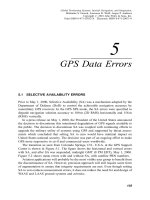
Figure 9.2 provides an overview of the functional elements of the GUS control
loop. The control loop contains algorithm elements (shaded boxes) and hardware
elements that either provide inputs to the algorithm or are controlled or affected by
outputs from the algorithm. The hardware elements include a WAAS GPS receiver,
GEO satellite, and GUS signal generator.
Downlink ionospheric delay is estimated in the ionospheric delay and rate
estimator using pseudorange measurements from the WAAS GPS receiver on L
1
and L
2
(downconverted from the GEO C-band downlink at the GUS). This is a two-
state Kalman ®lter that estimates the ionospheric delay and delay rate.
At each measurement interval, a range measurement is taken and fed into the
range, rate, and acceleration estimator. This measurement is the average between the
reference pseudorange from the GUS signal generator PR
sign
and the received
pseudorange from the L
1
downlink as measured by the WAAS GPS Receiver PR
geo
and adjusted for estimated ionospheric delay PR
iono
. The equation for the range
measurement is then
z
1
2
PR
geo
À PR
iono
PR
sign
ÀT
Cup
À T
L1dwnS
;
where T
Cup
C-band uplink delay m
T
L1dwnS
L
1
receiver delay of the GUS m
The GUS signal generator is initialized with a pseudorange value from satellite
ephemeris data. This is the initial reference from which corrections are made.
The range, rate and acceleration estimator is a three-state Kalman ®lter that drives
the frequency and code control loops.
270
DIFFERENTIAL GPS
The code control loop is a second-order control system. The error signal for this
control system is the difference between the WAAS pseudorange (P
rsign
and the
estimated pseudorange from the Kalman ®lter. The loop output is the code rate
adjustments to the GUS signal generator.
The frequency control loop has two modes. First, it adjusts the signal generator
frequency to compensate for uplink Doppler effects. This is accomplished using a
®rst-order control system. The error signal input is the difference between the L
1
Doppler frequency from the WAAS GPS receiver and the estimated range rate
(converted to a Doppler frequency) from the Kalman ®lter.
Once the frequency error is below a threshold value, the carrier phase is
controlled. This is accomplished using a second-order control system. The error
signal input to this system is the difference between the L
1
carrier phase and a carrier
phase estimate based on the Kalman ®lter output. This estimated range is converted
to carrier cycles using the range estimate at the time carrier phase control starts as a
reference. Fine adjustments are made to the signal generator carrier frequency to
maintain phase coherence [35, 47±49, 94].
9.3.2 In-Orbit Tests
Two separate series of in-orbit tests (IOTs) were conducted, one at the COMSAT
GPS Earth Station (GES) in Santa Paula, California with Paci®c Ocean Region
(POR) and Atlantic Ocean Region-West (AOR-W) I-3 satellites and the other at the
COMSAT GES in Clarksburg, Maryland, using AOR-W. The IOTs were conducted
Iono delay
rate
estimator
PR
iono
PR
iono
Range, rate
acceleration
estimator
Code control
loop
Frequency
control
loop
GUS signal
generator
Iono delay
estimate
Iono delay
estimate
Range & rat
e
estimates
WAAS GPS
receiver
GEO
satellite
Initialization from
ephemeris
Cup
Control
bit
Control
Range, rate
residual
Iono delay
estimator
L1 and cdwn
PRL1 ÐPRL2 (cdwn)
P
R
SIGN
P
R
GEO
Pseudo
range
WAAS
pseudo range
Range
measurement
L1 doppler frequency L1 carrier phase
GUS control loop algorithim
Σ
Fig. 9.2 GUS control loop block diagram.
9.3 GEO UPLINK SUBSYSTEM(GUS)
271
to validate a prototype version of the GUS control loop algorithm. Data was
collected to verify the ionospheric estimation and code±carrier coherence perfor-
mance capability of the control loop and the short±term carrier frequency stability of
the I-3 satellites with a prototype ground station. The test results were also used to
validate the GUS control loop simulation.
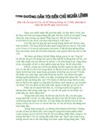
Figure 9.3 illustrates the IOTsetup at a high level. Prototype ground station
hardware and software were used to assess algorithm performance at two different
ground stations with two different Inmarsat-3 satellites.
9.3.3 Ionospheric Delay Estimation
The GUS control loop estimates the ionospheric delay contribution of the GEO C-
band uplink to maintain code±carrier coherence of the broadcast SIS. Figures 9.4±
9.6 provide the delay estimates for POR using the Santa Paula GES and AOR-W
using both the Santa Paula and Clarksburg GES. Each plot shows the estimated
ionospheric delay (output of the two-state Kalman ®lter) versus the calculated delay
using the L
1
and C pseudorange data from a WAAS GPS receiver. Calculated delay
is noisier and varying about 1 m=s, whereas the estimated delay by the Kalman ®lter
is right in middle of the measured delay, as shown in Figures 9.4±9.6. Delay
measurements were calculated using the equation
Ionospheric delay
P
RL1
À P
RC
À tau L
1
tau C
1 ÀL
1
freq
2
=C freq
2
AOR-W
POR
HPA
Cup
L1 dwn
L2
Cdwn
Frequency
reference
Frequency
reference
Frequency
reference
Measurement
data
Signal
generator
C-band
upconverter
C-band to L2
downconverter
L1-omni
antenna
Frequency
reference
WAAS phase 1 equipment
Processor/
controller
• prototype
algorithm
software
WAAS GPS
receiver
FTS
atomic
clock
IF
Fig. 9.3 IOT test GUS setup.
272
DIFFERENTIAL GPS
where P
RL1
L
1
pseudorange m
P
RC
C pseudorange m
tau L
1
L
1
downlink delay m
tau C C downlink delay m
L
1
freq L
1
frequency; 1575:42 MHz
Cfreq C frequency; 3630:42 MHz
The ionosphere during the IOTs was fairly benign with no high levels of solar
activity observed. Table 9.1 provides the ionospheric delay statistics (in meters)
Fig. 9.4 Measured and estimated ionospheric delay, POR, Santa Paula.
Fig. 9.5 Measured and estimated ionospheric delay, AOR-W, Santa Paula.
9.3 GEO UPLINK SUBSYSTEM(GUS)
273
between the output of the ionospheric Kalman ®lter in the control loop, and the
calculated delay from the WAAS GPS receiver's L
1
and L
2
pseudoranges. The
statistics show that the loop's ionospheric delay estimation is very close (low RMS)
to the ionospheric delay calculated using the measured pseudorange from the WAAS
GPS receiver.
9.3.4 Code±Carrier Frequency Coherence
The GEO's broadcast code±carrier frequency coherence requirement is speci®ed in
the WAAS System Speci®cation and Appendix A of reference [106]. It states:
The lack of coherence between the broadcast carrier phase and the code phase shall be
limited. The short term fractional frequency difference between the code phase rate and
the carrier frequency will be less than 5 Â 10
À11
: That is,
f
code
1:023 MHz
À
f
carrier
1575:42 MHz
< 5Â 10
À11
Fig. 9.6 Measured and estimated ionospheric delay, Clarksburg.
TABLE 9.1 Observed RMS WAAS Ionospheric Correc-
tion Errors
In-Orbit Test RMS Error (m)
Santa Paula GES, Oct. 10, 1997, POR 0.20
Santa Paula GES, Dec. 1, 1997, AOR-W 0.45
Clarksburg GES, Mar. 20, 1998, AOR-W 0.34
274
DIFFERENTIAL GPS