Tài liệu Timing and Delay part 2 ppt
Bạn đang xem bản rút gọn của tài liệu. Xem và tải ngay bản đầy đủ của tài liệu tại đây (32.38 KB, 9 trang )
[ Team LiB ]
10.2 Path Delay Modeling
In this section, we discuss various aspects of path delay modeling. In this section, the
terms pin and port are used interchangeably.
10.2.1 Specify Blocks
A delay between a source (input or inout) pin and a destination (output or inout) pin of a
module is called a module path delay. Path delays are assigned in Verilog within the
keywords specify and endspecify. The statements within these keywords constitute a
specify block.
Specify blocks contain statements to do the following:
•
Assign pin-to-pin timing delays across module paths
•
Set up timing checks in the circuits
•
Define specparam constants
For the example in Figure 10-3
, we can write the module M with pin-to-pin delays, using
specify blocks as follows:
Example 10-3 Pin-to-Pin Delay
//Pin-to-pin delays
module M (out, a, b, c, d);
output out;
input a, b, c, d;
wire e, f;
//Specify block with path delay statements
specify
(a => out) = 9;
(b => out) = 9;
(c => out) = 11;
(d => out) = 11;
endspecify
//gate instantiations
and a1(e, a, b);
and a2(f, c, d);
and a3(out, e, f);
endmodule
The specify block is a separate block in the module and does not appear under any other
block, such as initial or always. The meaning of the statements within specify blocks
needs to be clarified. In the following subsection, we analyze the statements that are used
inside specify blocks.
10.2.2 Inside Specify Blocks
In this section, we describe the statements that can be used inside specify blocks.
Parallel connection
As discussed earlier, every path delay statement has a source field and a destination field.
In the path delay statements in Example 10-3
, a, b, c, and d are in the position of the
source field and out is the destination field.
A parallel connection is specified by the symbol => and is used as shown below.
Usage: ( <source_field> => <destination_field>) = <delay_value>;
In a parallel connection, each bit in source field connects to its corresponding bit in the
destination field. If the source and the destination fields are vectors, they must have the
same number of bits; otherwise, there is a mismatch. Thus, a parallel connection specifies
delays from each bit in source to each bit in destination.
Figure 10-4
shows how bits between the source field and destination field are connected
in a parallel connection. Example 10-4
shows the Verilog description for a parallel
connection.
Example 10-4 Parallel Connection
//bit-to-bit connection. both a and out are single-bit
(a => out) = 9;
//vector connection. both a and out are 4-bit vectors a[3:0], out[3:0]
//a is source field, out is destination field.
(a => out) = 9;
//the above statement is shorthand notation
//for four bit-to-bit connection statements
(a[0] => out[0]) = 9;
(a[1] => out[1]) = 9;
(a[2] => out[2]) = 9;
(a[3] => out[3]) = 9;
//illegal connection. a[4:0] is a 5-bit vector, out[3:0] is 4-bit.
//Mismatch between bit width of source and destination fields
(a => out) = 9; //bit width does not match.
Figure 10-4. Parallel Connection
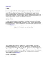
Full connection
A full connection is specified by the symbol *> and is used as shown below.
Usage: ( <source_field> *> <destination_field>) = <delay_value>;
In a full connection, each bit in the source field connects to every bit in the destination
field. If the source and the destination are vectors, then they need not have the same
number of bits. A full connection describes the delay between each bit of the source and
every bit in the destination, as illustrated in Figure 10-5
.
Figure 10-5. Full Connection
Delays for module M were described in Example 10-3
, using a parallel connection.
Example 10-5
shows how delays are specified by using a full connection.
Example 10-5 Full Connection
//Full Connection
module M (out, a, b, c, d);
output out;
input a, b, c, d;
wire e, f;
//full connection
specify
(a,b *> out) = 9;
(c,d *> out) = 11;
endspecify
and a1(e, a, b);
and a2(f, c, d);
and a3(out, e, f);
endmodule
The full connection is particularly useful for specifying a delay between each bit of an
input vector and every bit in the output vector when bit width of the vectors is large. The
following example shows how the full connection sometimes specifies delays very
concisely.
//a[31:0] is a 32-bit vector and out[15:0] is a 16-bit vector
//Delay of 9 between each bit of a and every bit of out
specify
( a *> out) = 9; // you would need 32 X 16 = 352 parallel connection
// statements to accomplish the same result! Why?
endspecify
Edge-Sensitive Paths
An edge-sensitive path construct is used to model the timing of input to output delays,
which occurs only when a specified edge occurs at the source signal.
//In this example, at the positive edge of clock, a module path
//extends from clock signal to out signal using a rise delay of 10
//and a fall delay of 8. The data path is from in to out, and the
//in signal is not inverted as it propagates to the out signal.
(posedge clock => (out +: in)) = (10 : 8);
specparam statements
Special parameters can be declared for use inside a specify block. They are declared by
the keyword specparam. Instead of using hardcoded delay numbers to specify pin-to-pin
delays, it is common to define specify parameters by using specparam and then to use
those parameters inside the specify block. The specparam values are often used to store
values for nonsimulation tools, such as delay calculators, synthesis tools, and layout
estimators. A sample specify block with specparam statements is shown in Example 10-6
.
Example 10-6 Specparam
//Specify parameters using specparam statement
specify
//define parameters inside the specify block
specparam d_to_q = 9;
specparam clk_to_q = 11;
(d => q) = d_to_q;
(clk => q) = clk_to_q;
endspecify
Note that specify parameters are used only inside their own specify block. They are not
general-purpose parameters that are declared by the keyword parameter. Specify
parameters are provided for convenience in assigning delays. It is recommended that all
pin-to-pin delay values be expressed in terms of specify parameters instead of hardcoded
numbers. Thus, if timing specifications of the circuit change, the user has to change only
the values of specify parameters.
Conditional path delays
Based on the states of input signals to a circuit, the pin-to-pin delays might change.
Verilog allows path delays to be assigned conditionally, based on the value of the signals
in the circuit. A conditional path delay is expressed with the if conditional statement. The
operands can be scalar or vector module input or inout ports or their bit-selects or part-
selects, locally defined registers or nets or their bit-selects or part-selects, or compile time
constants (constant numbers and specify block parameters). The conditional expression
can contain any logical, bitwise, reduction, concatenation, or conditional operator shown
in Table 6-1
on page 96. The else construct cannot be used. Conditional path delays are
also known as state dependent path delays(SDPD).
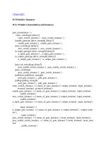
Example 10-7 Conditional Path Delays
//Conditional Path Delays
module M (out, a, b, c, d);
output out;
input a, b, c, d;
wire e, f;