Tài liệu Parallel Port Complete- P2 doc
Bạn đang xem bản rút gọn của tài liệu. Xem và tải ngay bản đầy đủ của tài liệu tại đây (163.92 KB, 20 trang )
Chapter 1
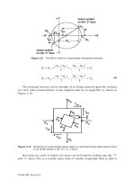
Figure 1-2: The photo on the left shows the back panel of an expansion card, with
a parallel port's 25-pin female D-sub connector on the left side of the panel. (The
other connector is for a video monitor.) The photo on the right shows the 36-pin
female Centronics connector used on most printers.
fer information between the parallel port and the CPU, memory, and other system
components.
Connectors
The PC's back panel has the connector for plugging in a cable to a printer or other
device with a parallel-port interface. Most parallel ports use the 25-contact D-sub
connector shown in Figure 1-2. The shell (the enclosure that surrounds the con-
tacts) is roughly in the shape of an upper-case D. Other names for this connector
are the subminiature D, DB25, D-shell, or just D connector. The IEEE 1284 stan-
dard for the parallel port calls it the IEEE 1284-A connector.
Newer parallel ports may use the new, compact, 36-contact IEEE 1284-C connec-
tor described in Chapter 6.
The connector on the computer is female, where the individual contacts are sock-
ets, or receptacles. The cable has a mating male connector, whose contacts are
pins, or plugs.
The parallel-port connector is usually the only female 25-pin D-sub on the back
panel, so there should be little confusion with other connectors. Some serial ports
use a 25-contact D-sub, but with few exceptions, a 25-pin serial D-sub on a PC is
male, with the female connector on the cable-the reverse of the parallel-port
convention. (Other serial ports use 9-pin D-subs instead.)
SCSI is another interface whose connector might occasionally be confused with
the parallel port's. The SCSI interface used by disk drives, scanners, and other
devices usually has a 50-contact connector, but some SCSI devices use a 25-con-
tact D-sub that is identical to the parallel-port's connector.
If you're unsure about which is the parallel-port connector, check your system
documentation. When all else fails, opening up the enclosure and tracing the cable
from the connector to an expansion board may offer clues.
1
0
Parallel Port Complete
Please purchase PDF Split-Merge on www.verypdf.com to remove this watermark.
The Circuits Inside
Cables
Essentials
Inside the computer, the parallel-port circuits may be on the motherboard or on a
card that plugs into the expansion bus.
The motherboard is the main circuit board that holds the computer's microproces-
sor chip as well as other circuits and slots for expansion cards. Because just about
all computers have a parallel port, the port circuits are often right on the mother-
board, freeing the expansion slot for other uses. Notebook and laptop computers
don't have expansion slots, so the port circuits in these computers must reside on
the system's main circuit board.
The port circuits connect to address, data, and control lines on the expansion bus,
and these in turn interface to the microprocessor and other system components.
Most printer cables have a 25-pin male D-sub connector on one end and a male
36-contact connector on the other. Many refer to the 36-contact connector as the
Centronics connector, because it's the same type formerly used on Centronics
printers.
Other names are parallel-interface connector or just printer connector.
IEEE 1284 calls it the 1284-B connector.
Peripherals other than printers may use different connectors and require different
cables. Some use a 25-pin D-sub like the one on the PC. A device that uses only a
few of the port's signals may use a telephone connector, either a 4-wire RJI I or
an 8-wire RJ45. Newer peripherals may have the 36-contact 1284-C connector.
In any case, because the parallel-port's outputs aren't designed for transmitting
over long distances, it's best to keep the cable short: 6 to 10 feet, or 33 feet for an
IEEE-1284-compliant cable. Chapter 6 has more on cable choices.
Multiple Uses for One Port
If you have more than one parallel-port peripheral, the easiest solution is to add a
port for each. But there may be times when multiple ports aren't an option. In this
case, the alternatives are to swap cables as needed, use a switch box, or
daisy-chain multiple devices to one port.
If you use only one device at a time and switch only occasionally, it's easy enough
to move the cable when you want to use a different device.
For frequent swapping, a more convenient solution is a switch box. A typical
manual switch box has three female D-sub connectors. A switch enables you route
Parallel Port Complete
1
1
Please purchase PDF Split-Merge on www.verypdf.com to remove this watermark.
Chapter 1
the contacts of one connector to either of the others. To use the switch box to
access two peripherals on one port, you'll need a cable with two male D-subs to
connect the PC to the switch box, plus an appropriate cable from the switch box to
each peripheral.
You can also use a switch box to enable two PCs to share one printer or other
peripheral. This requires two cables with two male D-subs on each, and one
peripheral cable. Switch boxes with many other connector types are also avail-
able.
Manual switches are inexpensive, though some printer manufacturers warn that
using them may damage the devices they connect to. A safer choice is a switch
that uses active electronic circuits to route the signals. Some auto-sensing
switches enable you to connect multiple computers to one printer, with first-come,
first-served access.
When a printer is idle, any computer can access it. When the
printer is in use, the switch prevents the other computers from accessing it. How-
ever, these switches may not work properly if the peripherals use bidirectional
communications, or if the peripheral uses the control or status signals in an uncon-
ventional way.
The parallel ports on some newer peripherals support a daisy-chain protocol that
allows up to eight devices to connect to a single port. The PC assigns a unique
address to each peripheral, which then ignores communications intended for the
other devices in the chain. The software drivers for these devices must use the
protocol
when they access the port. The last device in the chain can be
daisy-chain-unaware; it doesn't have to support the protocol. Chapter 11 has more
on daisy chains.
Security Keys
Security keys, or dongles, are a form of copy protection that often uses the parallel
port. Some software-usually expensive, specialized applications-includes a
security key that you must plug into the parallel port in order to run the software.
If you don't have the key installed, the software won't run.
The key is a small device with a male D-sub connector on one end and a female
D-sub on the other. You plug the key into the parallel-port connector, then plug
your regular cable into the security key. When the software runs, it attempts to
find and communicate with the key, which contains a code that the software rec-
ognizes. The key usually doesn't use any conventional handshaking signals, so it
should be able to live in harmony with other devices connected to the port.
1
2
Parallel Port Complete
Please purchase PDF Split-Merge on www.verypdf.com to remove this watermark.
The keys do require power, however. If you have a key that draws more than a
small amount of current, and if your parallel port has weak outputs, you may have
problems in using other devices on the same port as the key.
Alternatives to the Parallel Port
The parallel port is just one of many ways to interface inputs and outputs to a
computer. In spite of its many virtues, the parallel port isn't the best solution for
every project. These are some of the alternatives:
Serial Interfaces
Parallel Port Complete
Essentials
One large group of parallel-port alternatives is serial interfaces, where data bits
travel on a single wire or pair of wires (or in the case of wireless links, a single
transmission path.) Both ends of the link require hardware or software to translate
between serial and parallel data. There are many types of serial interfaces avail-
able for PCs, ranging from the ubiquitous RS-232 port to the newer RS-485, USB,
IEEE-1394, and IrDA interfaces.
RS-232
Just about every PC has at least one RS-232 serial port. This interface is especially
useful when the PC and the circuits that you want to connect are physically far
apart.
As a rule, parallel-port cables should be no longer than 10 to 15 feet, though the
IEEE-1284 standard describes an improved interface and cable that can be 10
meters (33 feet). In contrast, RS-232 links can be 80 feet or more, with the exact
li
mit depending on the cable specifications and the speed of data transfers.
RS-232 links are slow, however. Along with each byte, the transmitting device
normally adds a start and stop bit. Even at 115,200 bits per second, which is a typ-
ical
maximum rate for a serial port, the data-transfer rate with one start and stop
bit per byte is just 11,520 bytes per second.
RS-485
Another useful serial interface is RS-485, which can use cables as long as 4000
feet and allows up to 32 devices to connect to a single pair of wires. You can add
an expansion card that contains an RS-485 port, or add external circuits that con-
vert an existing RS-232 interface to RS-485. Other interfaces similar to RS-232
and RS-485 are RS-422 and RS-423.
1
3
Please purchase PDF Split-Merge on www.verypdf.com to remove this watermark.
Chapter 1
Universal Serial Bus
A new option for I/O interfacing is the Universal Serial Bus (USB), a project of a
group that includes Intel and Microsoft. A single USB port can have up to 127
devices communicating at either 1.5 Megabits/second or 12 Megabits/second over
a 4-wire cable. The USB standard also describes both the hardware interface and
software protocols. Newer PCs may have a USB port built-in, but because it's so
new, most existing computers can't use it without added hardware and software
drivers.
I
EEE 1394
The IEEE-1394 high-performance serial bus, also known as Firewire, is another
new interface. It allows up to 63 devices to connect to a PC, with transmission
rates of up to 400 Megabits per second. The 6-wire cables can be as long as 15
feet, with daisy chains extending to over 200 feet. The interface is especially pop-
ular for connecting digital audio and video devices. IEEE-1394 expansion cards
are available for PCs.
IrDA
The IrDA (Infrared Data Association) interface allows wireless serial communica-
tions over distances of 3 to 6 feet. The link transmits infrared energy at up to
115,200 bits/second. It's intended for convenient (no cables or connectors) trans-
mitting of files between a desktop and laptop computer, or any short-range com-
munications where a cabled interface is inconvenient. Some computers and
peripherals now have IrDA interfaces built-in.
Other Parallel Interfaces
SCSI and IEEE-488 are two other parallel interfaces used by some PCs.
SCSI
SCSI (small computer system interface) is a parallel interface that allows up to
seven devices to connect to a PC along a single cable, with each device having a
unique address. Many computers use SCSI for interfacing to internal or external
hard drives, tape back-ups, and CD-ROMs. SCSI interfaces are fast, and the cable
can be as long as 19 feet (6 meters). But the parallel-port interface is simpler,
cheaper, and much more common.
I
EEE 488
The IEEE-488 interface began as Hewlett Packard's GPIB (general-purpose inter-
face bus). It's a parallel interface that enables up to 15 devices to communicate at
1
4
Parallel Port Complete
Please purchase PDF Split-Merge on www.verypdf.com to remove this watermark.
Custom I/O Cards
PC Cards
Essentials
speeds of up to 1 Megabyte per second. This interface has long been popular for
interfacing to lab instruments. Expansion cards with IEEE-488 interfaces are
available.
Many other types of input and output circuits are available on custom expansion
cards.
An advantage of these is that you're not limited by an existing interface
design. The card may contain just about any combination of analog and digital
inputs and outputs. In addition, the card may hold timing or clock circuits, func-
tion generators, relay drivers, filters, or just about any type of component related
to the external circuits. With the standard parallel port, you can add these compo-
nents externally, but a custom I/O card allows you to place them inside the com-
puter.
To use an expansion card, you of course need an empty expansion slot, which
isn't available in portable computers and some desktop systems. And the custom
hardware requires custom software.
Finally, instead of using the expansion bus, some UO cards plug into a PC Card
slot,
which accepts slim circuit cards about the size of a playing card. An earlier
name for these was PCMCIA cards, which stands for
Personal Computer Memory
Card International Association,
whose members developed the standard. Many
portable computers and some desktop models have PC-Card slots. Popular uses
include modems and data acquisition circuits. There are even PC Cards that func-
tion as parallel ports. You don't need an internal expansion slot, and you don't
have to open up the computer to plug the card in. But again, the standard paral-
lel-port interface is cheaper and more widely available.
Please purchase PDF Split-Merge on www.verypdf.com to remove this watermark.
Chapter 1
16
Parallel Port Complete
Please purchase PDF Split-Merge on www.verypdf.com to remove this watermark.
Accessing Ports
Windows, DOS, and Visual Basic provide several ways to read and write to paral-
lel ports. The most direct way is reading and writing to the port registers. Most
programming languages include this ability, or at least allow you to add it. Visual
Basic includes other options, including the
Printer
object, the
PrintForm
method,
and
Open LPTx.
Windows also has API calls for accessing LPT ports, and 16-bit
programs can use BIOS and DOS software interrupts for LPT access.
This chapter introduces the parallel port's signals and ways of accessing them in
the programs you write.
The Signals
Parallel Port Complete
Accessing Ports
Table 2-1 shows the functions of each of the 25 contacts at the parallel port's
connector, along with additional information about the signals and their corre-
sponding register bits. Table 2-2 shows the information arranged by register rather
than by pin number, and including register bits that don't appear at the connector.
Most of the signal names and functions are based on a convention established by
the Centronics Data Computer Corporation, an early manufacturer of dot-matrix
printers. Although Centronics no longer makes printers, its interface lives on.
1
7
Please purchase PDF Split-Merge on www.verypdf.com to remove this watermark.