Tài liệu Pneumatic Transporters docx
Bạn đang xem bản rút gọn của tài liệu. Xem và tải ngay bản đầy đủ của tài liệu tại đây (273.95 KB, 4 trang )
FIBRO GmbH · Standard Parts Division · Postfach 1120 · D-74851 Hassmersheim · Tel. 0 62 66-73-0* · Fax 0 62 66-73-237 · · www.fibro.com
Product No. 2.5800.01.0304.01000
03/2004
2·18279· 2003·1
°
Pneumatic Transporters
2· 18284·2003·1
°
subject to alterations
2199.03/2199.10
Pneumatic conveyors 2199.40/2199.70
Description
This pneumatic conveyor is unique and is patented. It was
designed to provide an effective and affordable solution to the
problems of conveying parts and disposing of waste.
This beltless system conveys stampings and waste from the tool
area by vibration alone.
A specially designed guide channel which is screwed to the body
of the conveyor vibrates rhythmically slowly forwards and fast
backwards The mass inertia of the parts is used to move them
forwards. In this way the parts in the guide channel progress
gently towards the storage containers.
The conveyor is maintenance-free and has a very low air
consumption so is extremely economical in operation.
The pneumatic conveyor is quiet running and very user friendly.
The conveyor was originally designed for press room use but can
be used as a conveyor with any tool. Blockages are a thing of
the past whether the conveyor is feeding parts for assembly or
removing and disposing of stampings and waste parts.
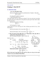
Guides
Technical data:
load, max. air consumption sound level stroke length guide channel weight despatch weight
Model (kg) (l/min.) (db-A) (mm) max. (kg) (kg)
2199.03 3 14 68 20 1,4 1,4
2199.10 10 20 68 25 2,7 2,8
2199.40 40 42 70 27 5,4 7,2
2199.70 70 40 70 27 11,3 5,5
1. Recommended rate of vibration: 120 per minute · 2. Speed of travel: 8–10 m / min. · 3. Operating pressure: 4–5.5 bar
4. Slope of guide channel: max. 8°
Support roller
Conveyor
Bed
Sliding plain
bearings
SpacerSupport bracket
Guide
channel
Direction of travelBall bearing
We recommend three options for supporting a long guide channel:
1) Ball bearings 2) Roller supports 3) Sliding plain bearings
Ball bearing
support
Support
roller
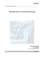
2199.03/2199.10
2199.40/2199.70 Pneumatic conveyors
subject to alterations
120
96
2
51
24
184,5
130
34
150
102
150
(10)
83
140
2199.03
125
105
60
216
(15)
30
20
145
115
4567
16
80
58
2199.10
11
15
42,5
50
100
102,5
250,5
145
68 32 88
8
92
160
120
2199.40
(28,5)
(6,5)
127
70
98
140
265151
14
63,5 40,5
208
75
47
63,5
77
38 30
2199.70
2· 18289·2003·1
°
M6 x 8 mm
deep (6x)
(4x with counter-
sink for counter-
sunk
screws)
for M8 with countersink for
countersunk screw (4 x)
6 x for M8 with countersink
for countersunk screw
1
/
8
NPT air inlet
1
/
4
NPT air inlet
1
/
4
NPT air inlet
1
/
4
NPT air inlet
Stroke 20
Stroke 25
Stroke 27
Stroke 27
for M8 (4x)
M6x8
deep (6x)
M8x9
deep (6x)
M8x9 deep (6x)
max. 325
2· 18294·2003·1
°
subject to alterations
2199.03/2199.10
Pneumatic conveyors 2199.40/2199.70
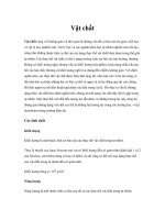
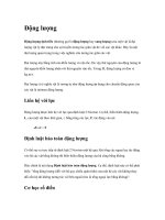
2199.03/.10/.40/.70
How does the pneumatic
conveyor work?
This compact pneumatic conveyor is driven by
compressed air. The vibrating rhythmic motion
conveys stampings and stamping waste whilst
reducing your costs. Guide channels can be
matched to any tool opening and used for sorting
various types of waste.
The guide channels are highly adaptable.
Model
2199.10
Stage 3: Finished item
Stage 2: Stamping
waste
Top plate
pneumatic conveyor,
model 2199.40
upper guide channel for
conveying parts
Stage 1:
Stamping waste
Punch
Bottom bolster
Follow-on tool
Waste metal
Base
Direction of
conveyor movement
Spacer
Finished item
Lower guide channel
for waste removal
Mounting for
lower guide channel
Stripping unit
Matrixes