Tài liệu RECEIVER TYPES AND CHARACTERISTICS doc
Bạn đang xem bản rút gọn của tài liệu. Xem và tải ngay bản đầy đủ của tài liệu tại đây (56.7 KB, 5 trang )
CRYSTAL VIDEO RECEIVER
YIG TUNED NARROWBAND SUPERHET
WIDEBAND SUPERHET
INSTANTANEOUS FREQUENCY MEASUREMENT
LIMITING
AMPLIFIER
DELAY
LINE
FREQUENCY
INFORMATION
SIN
COS
IF AMP
TUNING
VIDEO
BAND 1
VIDEO
BAND 2
VIDEO
BAND 3
VIDEO
RF AMPLIFIER
COMPRESSIVE
VIDEO
AMPLIFIER
YIG
FILTER
LOG
VIDEO
AMP
IF FILTER
YIG
OSCILLATOR
PHASE
DETECTOR
VIDEO
CONVERSION
WIDEBAND
FILTER
FIXED
FREQUENCY
OSCILLATOR
IF FILTER
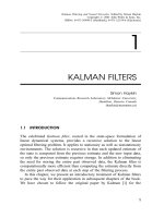
5-3.1
Figure 1. Common ESM Receiver Block Diagrams
RECEIVER TYPES AND CHARACTERISTICS
Besides the considerations of noise and noise figure, the capabilities of receivers are highly dependant on the type
of receiver design. Most receiver designs are trade-offs of several conflicting requirements. This is especially true of the
Electronic Support Measures (ESM) receivers used in Electronic Warfare.
This section consists of a figure and tables that provide a brief comparison of various common ESM receiver types.
Figure 1 shows block diagrams of four common ESM receivers. Table 1 is a comparison of major features of receivers.
Table 2 shows the receiver types best suited for various types of signals and Tables 3 and 4 compare several direction of
arrival (DOA) and emitter location techniques. Table 5 shows qualitative and quantitative comparisons of receiver
characteristics.
5-3.2
Table 1. Comparison of Major Features of Receivers
Receiver Advantages Disadvantages Principal Applications
Wideband Simple, inexpensive, instantaneous, No frequency resolution RWR
crystal video High POI in frequency range Poor sensitivity and Poor
simultaneous signal performance
Turned RF Simple, Frequency measurement Slow response time Option in RWR, Frequency
Crystal Video Higher sensitivity than wideband Poor POI measurement in hybrid
IFM Relatively simple Cannot sort simultaneous signals Shipboard ESM,
Frequency resolution Relatively poor sensitivity Jammer power management,
Instantaneous, high POI SIGINT equipment
Narrow-band High sensitivity Slow response time SIGINT equipment
scanning Good frequency resolution Poor POI Air and ship ESM
Superhet Simultaneous signals don't interfere Poor against frequency agility Analysis part of hybrid
Wide-band Better response time and POI Spurious signals generated Shipboard ESM
Superhet Poorer sensitivity Tactical air warning
Channelized Wide bandwidth, Near instantaneous, High complexity, cost; Lower SIGINT equipment
Moderate frequency resolution reliability; limited sensitivity Jammer power management
Microscan Near instantaneous, High complexity, SIGINT equipment
Good resolution and dynamic range, Limited bandwidth Applications for fine freq
Good simultaneous signal capability No pulse modulation information analysis over wide range
Critical alignment
Acousto-optic Near instantaneous, Good resolution, High complexity; new technology
Good simultaneous signal capability
Good POI
Table 2. Receiver Types vs. Signal Types
Signal
Type
Receiver Type
Wide-Band TRF Crystal IFM Narrow-Band Wide-Band Channelized Microscan Acousto-optic
Crystal Video Video Superhet Superhet
CW Special design Special Yes, but Yes Yes Yes Yes Yes
for CW design for interferes with
CW pulsed reception
Pulsed Yes Yes Yes Yes Yes Yes Yes Yes
Multiple No No No Yes, but won't No Yes Yes Yes
Frequency recognize as
same source
Frequency Yes, doesn't No Yes No Yes (within Yes Yes No/Yes,
Agile measure passband) depending on
frequency readout time
PRI Yes Yes Yes No/Yes, Yes Yes No/Yes, No/Yes,
Agile depending on imprecision depending on
scan rate in TOA readout time
Chirped Yes, within No Yes No/Yes, Yes Yes No/Yes, Yes (reduced
acceptance depending on (reduced depending sensitivity)
BW BW sensitivity) on scan rate
Spread Yes, within No Yes No No/Yes, Yes Yes Yes (reduced
Spectrum acceptance depending (reduced (reduced sensitivity)
BW on BW sensitivity) sensitivity)
DF
ACC
.
1
2
bW
)C
dB
24 S
DF
ACC
.
8
2 B d cos2
)2
5-3.3
Table 3. Direction of Arrival Measurement Techniques
Amplitude Comparison Phase Interferometer
Sensor Configuration Typically 4 to 6 Equal Spaced Antenna 2 or more RHC or LHC Spirals in Fixed
Elements for 360E Coverage Array
DF Accuracy
(Gaussian Antenna Shape)
DF Accuracy Improvement Decrease Antenna BW; Decrease Amplitude Increase Spacing of Outer Antennas;
Mistrack; Increase Squint Angle Decrease Phase Mistrack
Typical DF Accuracy 3E to 10E rms 0.1E to 3E rms
Sensitivity to High Sensitivity; Mistrack of Several dB Can Relatively Insensitive; Interferometer Can be
Multipath/Reflections Cause Large DF Errors Made to Tolerate Large Phase Errors
Platform Constraints Locate in Reflection Free Area Reflection Free Area; Real Estate for Array;
Prefers Flat Radome
Applicable Receivers Crystal Video; Channelizer; Acousto-Optic; Superheterodyne
Compressive; Superheterodyne
)C = Amplitude Monopulse Ratio in dB
dB
S= Squint Angle in degrees
2 = Antenna Beamwidth in degrees
BW
Table 4. Emitter Location Techniques
Measurement Technique Advantages Disadvantages
Triangulation Single Aircraft Non-instantaneous location
Inadequate accuracy for remote targeting
Not forward looking
Azimuth/elevation Single Aircraft Accuracy degrades rapidly at low altitude
Instantaneous location possible Function of range
Time Difference of Arrival Very high precision Very complex, diverse systems required,
(Pulsed signals) at least 3 aircraft
Can support weapon delivery position High quality receivers, DME (3 sites)
requirements very wideband data link
Very rapid, can handle short on-time threat Very high performance control processor;
requires very high reliability subsystems
5-3.4
Table 5. Qualitative Comparison of Receivers From NRL Report 8737
Feature
Receiver Type
Wide-Band TRF Crystal Narrow-Band Wide-Band
Crystal Video Video Superhet Superhet
IFM Channelized Microscan Acousto-optic
Instantaneous
Analysis Narrow Narrow Moderate Wide Wide Moderate
Bandwidth
Very Very
wide wide
Frequency Very Very
Resolution poor good
Fair Good Poor Fair Good Good
Sensitivity (No preamp) (No preamp) Fair Good
Poor Poor
Fair (preamp) Fair (preamp)
Fair/ Very Fair/ Very
good good good good
Dynamic Fair/ Very
Range good good
Fair Good Fair Good Fair Poor
Speed of Very Very Very Very
Acquisition Fast Fast Fast Fast
Slow Slow Fast Fast
Short pulse
Width Good Good Good Good Good Fair Fair
Capability
Very
good
Retention of
Signal Fair/ Fair/
Character- good good
istics
Fair Fair Poor Good Good Poor
Applicability
to Exotic Poor Good Poor Good
Signals
Poor/ Fair/ Fair/ Fair/
fair good good good
High signal Fair
Density Good Poor (depending on Good Poor
Performance BW)
Poor (high Fair/good,
false alarm Fair/ depending on
rate from good architecture
background) & processing
Simultaneous Fair
Signal Poor Poor Good (depending on Good Good Good
Capability BW)
Fair/
good
Processing processing
Complexity complex data
Moderate Moderate Low-high
depending on depending on Moderate Moderate Moderate depending on Complex
application application architecture
Simple signal
processing
Immunity Poor/ Poor/
to Jamming Fair Fair
Poor Fair Good Good Good Good
Power Low/ Moderate/
Requirements Moderate High
Low Moderate Moderate Moderate High Moderate
RF Range 0.15-18 channelized
(GHz) separate and down
Multi-
octave >0.5 to 40 <0.01 to 40 0.5 to 18 0.5 to 60 <0.5 to 8
(0.5-40)
0.5-4 (0.5-18
conversion)
Max Multi- Multi- 0.5 to 2
Instantane- octave octave depending
ous Analysis (to 17.5 (1 octave on PW
Bandwidth GHz) per unit) limitation
As high as ~2 GHz
desired with without
equivalent 50 MHz 500 MHz degradation, 1 GHz
reduction in 17.5 GHz with
resolution degradation
Frequency accuracy no accuracy no
Accuracy better than better than
Measurement Measurement
analysis BW analysis BW
5-10 MHz 0.5% to 1% 0.5 to 3 MHz ±1 MHz 10 KHz ±1 MHz
Feature
Receiver Type
Wide-Band TRF Crystal Narrow-Band Wide-Band
Crystal Video Video Superhet Superhet
IFM Channelized Microscan Acousto-optic
5-3.5
Pulse Width CW to CW to CW to 250 CW to
Range 50 ns 50 ns ns 0.5 µs
CW to ~20 ns CW to 100 ns CW to 4 ns CW to 30 ns
(depending with 20 MHz with 500 MHz (depending
on resolution) resolution resolution on resolution)
Frequency 100-500 0.5 to 1
Resolution MHz MHz
~400 MHz 10-125 MHz
(no better 25 MHz 1 MHz <0.1 MHz (less with 1 MHz
than BW) freq vernier)
Sensitivity (no preamp) than -80 preamp) -90, 1 MHz -80, 500 MHz -70, 10-50 -90, 5-10
(dBm) -80 (with with -75 (preamp) 4 BW BW MHz BW MHz BW
-40 to -50 Better -40 (no
preamp) preamp GHz BW
-70 to -80
Maximum 80 (w/preamp)
Dynamic 70 70-80 100+ 90 60 50-80 40-60 25-35
Range (dB) (saturated)
Tuning 1.0 s
Time (1 octave)
- 50 ms - (200 MHz - LO scan (integration
.12 s 0.3 µs 0.5 ms
band) time time)
Signal ID
Time
100 ns 50 ms 2-10 ms ~0.1 s - 2.10ms ~1 µs -
Minimum 35
Weight 30 60-75 (tuner 25 29-55
(lb) only)
20 (with unit) for 0.5
processor) 65-75 (full to 18 GHz
<20 (octave 1309-200
coverage) coverage
Size / Small Moderate
Minimum 300 Several
Volume (in³) (w/processor) thousand
Small 600-1000 Moderate 4000-8000 Moderate Small
375 ~100 1500-3000 (0.5-18 GHz 1200-2000 800-1900
Sm/Moderate Large
miniaturized coverage
Minimum ~50 150
Power (octave 150 (tuner 70-80 200
(W) unit) only)
100 (with 350 to 1200
processor) <10 60 (without for 0.5 to
without processor) 18 GHz
processor coverage
Cost Low Moderate High
Low/ Moderate/ Moderate/ Moderate/ Low/
Moderate High High High Moderate