Tài liệu Clutches and brakes design and selection P3 docx
Bạn đang xem bản rút gọn của tài liệu. Xem và tải ngay bản đầy đủ của tài liệu tại đây (835.77 KB, 36 trang )
3
ExternallyandInternallyPivotedShoe
Brakes
TypicalexternallyandinternallypivotedshoebrakesareshowninFigures1
and 2. In all but extremely rare designs, equal forces act upon both shoes to
produce equal applied moments about their pivots. External shoe brake
control is usually through a lever system that may be driven by electro-
mechanical, pneumatic, or hydraulic means. Internal shoe brake control is
usually by means of a double-ended cylinder or a symmetrical cam.
Calculation of the moments and shoe lengths to achieve a specified
braking torque cannot be carried out directly when the two shoes are pivoted
as shown in either of these figures and when the opposing shoes are sub-
jected to equal moments. The tedious task of manually iterating these
formulas to get a satisfactory design under these conditions may be eliminated
with the use of computer programs, such as those mentioned in the following
sections, that can quickly produce either graphical or numerical design
solutions.
I. PIVOTED EXTERNAL DRUM BRAKES
A. Long Shoe Brakes
Externally pivoted, long shoe brakes similar to that shown in Figure 1 are
often used as holding brakes. As its name implies, a holding brake is to hold a
shaft stationary until the brake is released. The compression spring on the left-
hand side of the brake in Figure 1 applies a clamping force to the brake shoes
Copyright © 2004 Marcel Dekker, Inc.
oneithersideofthebrakedrumtoholditstationarywithouttheneedfor
externalpower.Electricalcurrentthroughthesolenoidontheleftsideofthe
assemblyreleasesthebrakeandholdsitopenforaslongasvoltageisapplied
tothesolenoid.Otherholdingbrakesmayuseslightlydifferentmechanical
arrangementsandmayuseeitherahydraulicorapneumaticcylinderto
releasethebrake.
Oneoftheapplicationsofaholdingbrakeisinthedesignofanoverhead
crane.Thevalueofaholdingbrakeisthatitallowsaloadthathasbeenraised
tobeheldinpositionwithoutexternalpower.Thisisalsoasafetyfeature
becausethecranewillnotallowitsloadtoberaisedorlowereduntilthebrake
isintentionallyreleased.Likewise,thesebrakesarealsousedinhoists,in
punchandformingpresses,andinsomeconveyorsystems,forsimilar
reasons.
Webeginthederivationofthegoverningequationsforthebraking
torquebyconsideringonlyoneshoe(Figure3)andthenextendingthose
resultstomorethanoneshoe.Undertheassumptionthattheshoe,lever,and
drumareallrigid,andthatthestress–strainrelationsoftheliningarelinear,
F
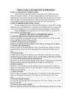
IGURE
1Externallypivotedshoebrake.(CourtesyAutomation&ProcessTech-
nology Div., Ametek Paoli, PA.)
Chapter 332
Copyright © 2004 Marcel Dekker, Inc.
F
IGURE
2 Internal pivoted shoe brake. (Courtesy of Dyneer Mercury Products,
Canton, Ohio.)
Externally and Internally Pivoted Shoe Brakes 33
Copyright © 2004 Marcel Dekker, Inc.
the pressure p at any position along the lining due to infinitesimal rotation yh
of the shoe about pivot A will be given by
p ¼ kRyh sin B ð1-1Þ
in terms of the quantities shown in Figure 3. Upon the introduction of the
maximum pressure, written as
p
max
¼ kRyh ðsin fÞ
max
ð1-2Þ
we find that
kRyh ¼
p
max
sin fðÞ
max
ð1-3Þ
so that after substitution from equation (1-3) into equation (1-1), we find that
the pressure may be written in terms of the maximum pressure as
p ¼
p
max
sin fðÞ
max
sin f ð1-4Þ
F
IGURE
3 Geometry involved in calculating moment M
p
about pivot point A.
Chapter 334
Copyright © 2004 Marcel Dekker, Inc.
Withthisexpressionforpressureasafunctionofposition,thetorqueonthe
drumwillbetheintegralovertheshoelengthoftheincrementalfrictionforce
A(prwÀdf)actingonthesurfaceofadrumofradiusr.Thus
T¼Ar
2
w
p
max
sinfðÞ
max
Z
f
2
f
1
sinfdfð1-5Þ
inwhich(sinf)
max
denotesthemaximumvalueofsinfwithintherange
f
1
VfVf
2
.Integrationofequation(1-5)yields
T¼
Ap
max
r
2
w
sinfðÞ
max
cosf
1
Àcosf
2
ðÞð1-6Þ
inwhichf
1
istheanglefromradiusRbetweenthedrumaxisandpivotA
tothenearedgeofthedrumsectorsubtendedbythebrakelining.As
drawninFigure3,anglef
2
ismeasuredfromradiusRtowardthefaredge
ofthebrakelining.Hencetheanglesubtendedbytheshoeisgivenby
f
0
¼f
2
Àf
1
ð1-7Þ
TocalculatethemomentthatmustbeappliedaboutpivotAinFigure3
toobtainthetorquefoundbyequation(1-6),wefirstcalculatethemoment
reactionatthepivotduetoboththeincrementalnormalforcesandthe
incrementalfrictionforcesactingonthelining.Anequalandopposite
momentmust,ofcourse,besuppliedtoactivatethebrake.
Radialforceprwdfoneachincrementalareaalsocontributestoa
pressuremomentM
p
aboutpivotA.RelativetothegeometryinFigure3,and
withtheaidofequation(1-4),thismomentmaybewrittenas
M
p
¼
Z
f
2
f
2
pwrdfðÞRsinf¼
p
max
wrR
sinfðÞ
max
Z
f
2
f
1
sin
2
fdfð1-8Þ
whichintegratesto
M
p
¼
p
max
wrR
4sinfðÞ
max
2f
0
Àsin2f
2
þsin2f
1
ðÞð1-9Þ
wheref
0
isgivenbyequation(1-7).Thismomentispositiveinthecounter-
clockwisedirection,anditsalgebraicsignisindependentofthedirectionof
drumrotationrelativetothebrakelever’spivotpoint.
ReactivemomentM
f
atpivotAduetothefrictionforceactingonthe
shoemaybecalculatedusingthegeometrysketchedinFigure4.Thus,
M
f
¼
Z
f
2
f
1
Apwr dfðÞR cos f À rðÞ
ð1-10Þ
¼
Ap
max
wr
sin fðÞ
max
Z
f
2
f
1
R cos f sin f À r sin fðÞdf
Externally and Internally Pivoted Shoe Brakes 35
Copyright © 2004 Marcel Dekker, Inc.
F
IGURE
4 Geometry involved in calculating moment M
f
about pivot point A.
Copyright © 2004 Marcel Dekker, Inc.
Integrationofequation(1-10)yields
M
f
¼
Ap
max
wr
4sinfðÞ
max
Rcos2f
1
Àcos2f
2
ðÞÀ4rcosf
1
Àcosf
2
ðÞ½ð1-11Þ
Herethequantityenclosedbythesquarebracketsdeterminesthealgebraic
signofM
f
andmaycauseittobezero.Thephysicalsignificanceoftheal-
gebraicsignfornonzerovaluesofmomentM
f
dependsuponthedirection
ofrotationNofthedrum.
Iftherotationistowardthepivot,asinFigure4,apositivevalueofM
f
signifies a clockwise moment about the pivot that applies the brake by forcing
the shoe against the drum, which would cause self-locking. Therefore, a
negative or zero value for M
f
from equation (1-11) is required to produce
either a counterclockwise or a zero moment, respectively, about the pivot
point.
The interpretation is reversed if the drum rotation N is away from the
pivot. In this case a positive value from equation (3.11) indicates a counter-
clockwise rotation of the shoe about the pivot that tends to release the brake.
Obviously, a negative value in this situation indicates a clockwise moment
about the pivot that tends to rotate the shoe toward the drum.
From these observations it follows that brake activation requires an
applied moment M
e
about the pivot point A such that
M
p
þ M
f
¼ M
e
> 0 N away from the pivot
M
p
À M
f
¼ M
e
> 0 N toward the pivot
ð1-12Þ
where M
f
itself, as calculated from equation (1-11), must be negative or zero
when rotation N is toward the pivot and positive or zero when it is away from
the pivot—hence the minus sign in the second of equations (1-12).
Self-locking is of use only when the brake is to serve as a backstop or as
an emergency brake during control failure. Otherwise, self-locking is gen-
erally to be avoided because it does not allow the braking torque to be
controlled by the control of M
e
.
B. Short Shoe Brakes
Short shoe brakes are generally defined as those for which the angular
dimension of the brake, f
0
, is small enough (generally less than 20j) that
sin f g (sin f)
max
and p g p
max
so that with these restrictions equation (1-5)
may be approximated by
T ¼ Apwr
2
f
0
¼ ArF ð1-13Þ
where
F ¼ pwr f
0
ð1-14Þ
Externally and Internally Pivoted Shoe Brakes 37
Copyright © 2004 Marcel Dekker, Inc.
istheforceexertedontheshortshoe.Applicationoftheseapproximationsto
equation(1-9)beforeintegrationyields
M
f
¼AFRcosf
1
ÀrðÞð1-15Þ
Similarly,applicationoftheseapproximationstoequation(1-10)before
integrationyields
M
p
¼FRsinf
1
ð1-16Þ
sothatsubstitutionintoequation(1-12)withtheminussignineffectreveals
thattheshortshoewillnotbeself-lockingif
sinf
1
ÀAcosf
1
À
r
R
>0ð1-17Þ
II.PIVOTEDINTERNALDRUMBRAKES
TheequationsderivedinSectionIAdealingwithlongexternalshoebrakes
applyequallywelltointernalshoedrumbrakes.Thereisoneessential
difference,however,thatdoesnotappearexplicitlyintheequationsthem-
selves:ThephysicalsignificanceofpositivevaluesofmomentsM
p
andM
f
is
different.Thegeometryusedtoobtaintheserelationsforinternalshoebrakes
isshowninFigures5and6;thedifferentinterpretationsforthevarious
combinationsofdirectionofrotationandinternalorexternalshoesarelisted
inTable1.Inthattablerotationofthedrumfromthefarendoftheshoes
totheendnearthepivot(termedrotationfromthetoeofthebraketotheheel)
isindicatedbyanarrowpointingtowardtheletterp;rotationintheopposite
directionisindicatedbyanarrowpointingawayfromtheletterp.Theacro-
nymcwindicatesclockwiserotation(orthedirectionofrotationofanad-
vancingright-handscrew),andccwindicatescounter-clockwiserotation.
FromFigure5itfollowsthat
dM
f
¼ Awrp d fðÞr À R cos fðÞ ð2-1Þ
This is the negative of the integrand in equation (1-10). The rotation indicated
causes the shoe to pivot in the counterclockwise direction about A; but
because equation (1-10) used the negative of the integrand above, the rotation
shown corresponds to a negative M
f
value as calculated using either equation
(1-10) or equation (1-11). Hence, negative M
f
from these formulas implies
counterclockwise rotation and positive M
f
corresponds to clockwise rotation
of the shoe about its pivot.
Braking requires a moment M
a
applied to the shoe as given by
M
p
À M
f
¼ M
a
N away from the pivot
M
p
þ M
f
¼ M
a
N toward the pivot
Chapter 338
Copyright © 2004 Marcel Dekker, Inc.
forinternalshoes.Thephysicalsignificanceofthealgebraicsignsassociated
withthemomentexpressionsderivedintheprecedingsectionsasappliedto
externalandinternalbrakesisdisplayedinTable1.Itismaybehelpfulthe
rewrite the equations for either internal or external brakes in terms of different
symbols if the use of a single set of equations for two different cases becomes
too confusing. After using these equations enough to become familiar with
them, the reader may find that analysis is easier if they are again combined
into a single set, as has been done here.
Drum brake efficiency may be measured in terms of the ratio of the
torque produced by the brake itself to the torque required to activate the
brake, also known as the shoe factor; namely,
T
M
a
¼
T
M
p
F M
f
ð2-2Þ
Brake efficiency is generally not a design factor in the analysis of drum brakes
because it is dependent on too many factors [f
1
, f
2
, r/R, A, w, and (sin f)
max
]
F
IGURE
5 Geometry for calculating the moment due to friction about point A for an
internal shoe brake.
Externally and Internally Pivoted Shoe Brakes 39
Copyright © 2004 Marcel Dekker, Inc.
to make it useful. More significance is usually associated with brake life, heat
dissipation, fading, and braking torque capability.
III. DESIGN OF DUAL-ANCHOR TWIN-SHOE DRUM
BRAKES
For both external and internal shoes and for either direction of rotation a
positive M
e
value indicates that an external moment of that magnitude must
be applied to activate the brake. The formulas also clearly indicate that the
extent of the braking action may be controlled by controlling this activation
moment. The role of M
f
, the moment due to friction, in determining the
required activation moment M
e
may be seen by returning to equation (1-11)
F
IGURE
6 Geometry for calculating the moment due to pressure about point A for
an internal shoe brake.
Chapter 340
Copyright © 2004 Marcel Dekker, Inc.
and observing that this moment may be either positive or negative, depending
on the choices for the quantities appearing in brackets.
One measure of the contribution of the friction moment to the entire
amount acting to force the shoe against the drum is the actuation factor,
defined by
M
f
M
a
sometimes de ned as
M
f
M
p
ð3-1Þ
which is independent of the torque produced by the brake.
If the quantities in brackets in equation (1-11) are chosen such that the
bracket becomes both negative and relatively large, M
f
may dominate M
p
and
M
a
becomes negatfive. This means that the brake has become self-locking:
contact between the shoe and the drum causes uncontrolled motion of the
shoe toward the drum. Since the resulting braking action is beyond the
control of the usual single-direction activation mechanism, self-locking is
generally to be avoided.
Return to relations (2-2), equate the denominators, and then divide both
sides by M
p
, which is always positive, to obtain
M
a
M
p
¼ 1 F
M
f
M
p
ð3-2Þ
Hence self-locking of external brakes in which the drum rotates toward the
pivot can be avoided if the relation M
f
/M
p
is always less than +1; if the drum
T
ABLE
1
Moment Relations for Internal and External Drum Brakes
Rotation
a
Moment
External shoe Internal shoe
Implied
braking action
Implied
shoe rotation
Implied
braking action
Implied
shoe rotation
p! M
p
> 0 Open ccw Open cw
pp M
p
> 0 Open ccw Open cw
p! M
f
> 0 Open ccw Close ccw
pp M
f
> 0 Close cw Open cw
Applied Moment Relations
External Shoe Internal Shoe
p! – M
p
+ M
f
= M
a
M
p
À M
f
= M
a
pp – M
p
À M
f
= M
a
M
p
+ M
f
= M
a
a
p !, Rotation toward the pivot; p p, rotation away from the pivot; cw, clockwise rotation; ccw,
counterclockwise rotation.
fi
Externally and Internally Pivoted Shoe Brakes 41
Copyright © 2004 Marcel Dekker, Inc.
rotatesawayfromthepivot,self-lockingcanbeavoidedifM
f
/M
p
isalways
greaterthanÀ1.Similarcriteriaholdforinternalbrakesexceptthatthe
directionsofrotationarereversedforthesamealgebraicsigns.Sincemost
brakesaredesignedforrotationinbothdirections,itisgenerallyconvenient
tocombinethesecriteriaintoasinglecriterion,whichisthatself-lockingof
bothinternalandexternaldrumbrakesmaybeavoidedif
À1V
M
f
M
p
Vþ1ð3-3Þ
Selectionofshoeanddrumanglesanddimensionsinaccordancewith
thiscriterionmaybeaidedbyconstructionofdesigncurvessuchasillustrated
inFigures7and8,inwhichtheratioM
f
/AM
p
isplottedagainstanglef
2
for
selectedvaluesofthecoefficientoffriction.Externalshoesarecharacterized
byR/rratiosgreaterthanunityandinternalshoesbyr/Rratioslessthan
unity.TheratioM
f
/AM
p
hasbeenplottedinsteadofM
f
/M
p
inFigures7and8
because it itself is independent of the coefficient of friction and thus must be
F
IGURE
7 Design curves for M
f
/(AM
p
)forB
1
=10j. r/R ratios for the upper, external
brake, curves are: 1—r/R = 0.2; 2—r/R = 0.4; 3—r/R = 0.6; 4—r/R = 0.8. r/R ratios
for the lower, internal brake, curves are: 5—r/R = 1.2; 6—r/R = 1.4; 7—r/R = 1.6;
8—r/R = 1.8.
Chapter 342
Copyright © 2004 Marcel Dekker, Inc.
plottedonlyonce.Touseitforanycoefficientoffrictionwithintherange
shown,itisonlynecessarytonotethattherequirementthattheratioM
f
/M
p
liebetweenÀ1and+1isequivalentto
À
1
A
V
M
f
AM
p
V
1
A
ð3-4Þ
Sincep
max
,(sinf)
max
,andAcanceloutwhenequation(1-11)isdivided
bytheproductofAandequation(1-9),theratioM
f
/(AM
p
)isafunctionofonly
threequantities:r/R,f
1
,andf
2
.Thus,M
p
/(AM
p
)maybeplottedasafunction
off
2
forfixedvaluesofr/Randf
1
,asinFigures7and8.Criterion(3.4)also
canbeincludedinthesegraphsbynotingthat1/A>0pertainstoexternal
drumbrakesand1/A<0pertainstointernaldrumbrakes,sothesevalues
maybeshownontheleft-handordinateofthesegraphsbyrelatingthemto
thelimitingvaluesofM
f
/(AM
p
)accordingtorelation(3.4),namely,thatatthe
lowerlimit,
À1=A¼M
f
=ðAM
p
Þ
F
IGURE
8DesigncurvesforM
f
/(AM
p
)forB
1
=45j. r/R ratios for the upper, external
brake, curves are: 1—r/R = 0.2; 2—r/R = 0.4; 3—r/R = 0.6; 4—r/R = 0.8. r/R ratios
for the lower, internal brake, curves are: 5—r/R = 1.2; 6—r/R = 1.4; 7—r/R = 1.6;
8—r/R = 1.8.
Externally and Internally Pivoted Shoe Brakes 43
Copyright © 2004 Marcel Dekker, Inc.
andthatattheupperlimit,
1=A¼M
f
=ðAM
p
Þ
Consequently,theordinatesontheright-handsidesofthegraphsinFigures7
and8arethereciprocalsoftheordinatesontheleft-handsides.Thus,wemay
read directly from these graphs that to be non-self-locking, the M
f
/(AM
p
)
ratio must fall below the 1/A value for external drum brakes, and it must fall
above the À1/A value for internal drum brakes.
Note that these curves show that the range of possible values for M
p
/
(AM
p
) that ensure that a dual-shoe brake will be free of self-locking decreases
as the lining coefficient of friction increases, as should be expected.
The length of a single shoe for a desired torque may be found algebrai-
cally from equation (1-6). However, selection of the shoe length to provide a
specified braking torque cannot be accomplished directly if two external or
two internal shoes operating about fixed pivot points, or anchor pins, are to be
used for greater braking torque.
Whenever two shoes are required and the arc length of the lining,
rf
0
= r(f
2
À f
1
), is to be selected, it is necessary to select f
1
, say, and then
find a value of f
2
such that the total torque T is the sum of T
a
and T
b
, where
T
a
represents the braking torque contribution from the shoe with the larger
peak pressure and T
b
represents the braking torque from the shoe with the
smaller peak pressure, p
b
. Torque T
a
, as given by the equation
T
a
¼
Ap
a
r
2
w
sin fðÞ
max
cos f
1
À cos f
2
ðÞ ð3-5Þ
will be the reference torque for both shoes. For simplicity in writing the
remaining equations it is convenient to introduce the quantities
A ¼ R 2f
2
À 2f
1
À sin 2f
2
þ sin 2f
1
ðÞ
B ¼ A R cos 2f
1
À cos 2f
2
ðÞÀ4r cos f
1
À cos f
2
ðÞ½ð3-6Þ
b
a
¼ p
a
bb
b
¼ p
b
bb¼
rw
4sinfðÞ
max
so that moments M
f
and M
p
may be written as
M
p
a
¼ b
a
AM
f
a
¼ b
a
B
M
p
b
¼ b
b
AM
f
b
¼ b
b
B
ð3-7Þ
In these terms the applied moment to one of the shoes may be written as
M
a
¼ b
a
min
A þ BðÞ
A À BðÞ
(
ð3-8Þ
Chapter 344
Copyright © 2004 Marcel Dekker, Inc.