Tài liệu cisco migration_Secure Wireless Design Guide 1.0 docx
Bạn đang xem bản rút gọn của tài liệu. Xem và tải ngay bản đầy đủ của tài liệu tại đây (10.22 MB, 272 trang )
Americas Headquarters
Cisco Systems, Inc.
170 West Tasman Drive
San Jose, CA 95134-1706
USA
Tel: 408 526-4000
800 553-NETS (6387)
Fax: 408 527-0883
Secure Wireless Design Guide 1.0
Cisco Validated Design I
July 11, 2007
Customer Order Number:
Text Part Number: OL-13990-01
Cisco Validated Design
The Cisco Validated Design Program consists of systems and solutions designed, tested, and
documented to facilitate faster, more reliable, and more predictable customer deployments. For more
information visit www.cisco.com/go/validateddesigns
.
ALL DESIGNS, SPECIFICATIONS, STATEMENTS, INFORMATION, AND RECOMMENDATIONS (COLLECTIVELY,
"DESIGNS") IN THIS MANUAL ARE PRESENTED "AS IS," WITH ALL FAULTS. CISCO AND ITS SUPPLIERS DISCLAIM
ALL WARRANTIES, INCLUDING, WITHOUT LIMITATION, THE WARRANTY OF MERCHANTABILITY, FITNESS FOR A
PARTICULAR PURPOSE AND NONINFRINGEMENT OR ARISING FROM A COURSE OF DEALING, USAGE, OR TRADE
PRACTICE. IN NO EVENT SHALL CISCO OR ITS SUPPLIERS BE LIABLE FOR ANY INDIRECT, SPECIAL,
CONSEQUENTIAL, OR INCIDENTAL DAMAGES, INCLUDING, WITHOUT LIMITATION, LOST PROFITS OR LOSS OR
DAMAGE TO DATA ARISING OUT OF THE USE OR INABILITY TO USE THE DESIGNS, EVEN IF CISCO OR ITS SUPPLIERS
HAVE BEEN ADVISED OF THE POSSIBILITY OF SUCH DAMAGES.
THE DESIGNS ARE SUBJECT TO CHANGE WITHOUT NOTICE. USERS ARE SOLELY RESPONSIBLE FOR THEIR
APPLICATION OF THE DESIGNS. THE DESIGNS DO NOT CONSTITUTE THE TECHNICAL OR OTHER PROFESSIONAL
ADVICE OF CISCO, ITS SUPPLIERS OR PARTNERS. USERS SHOULD CONSULT THEIR OWN TECHNICAL ADVISORS
BEFORE IMPLEMENTING THE DESIGNS. RESULTS MAY VARY DEPENDING ON FACTORS NOT TESTED BY CISCO.
CCVP, the Cisco Logo, and the Cisco Square Bridge logo are trademarks of Cisco Systems, Inc.; Changing the Way We Work, Live,
Play, and Learn is a service mark of Cisco Systems, Inc.; and Access Registrar, Aironet, BPX, Catalyst, CCDA, CCDP, CCIE, CCIP,
CCNA, CCNP, CCSP, Cisco, the Cisco Certified Internetwork Expert logo, Cisco IOS, Cisco Press, Cisco Systems, Cisco Systems
Capital, the Cisco Systems logo, Cisco Unity, Enterprise/Solver, EtherChannel, EtherFast, EtherSwitch, Fast Step, Follow Me
Browsing, FormShare, GigaDrive, GigaStack, HomeLink, Internet Quotient, IOS, iPhone, IP/TV, iQ Expertise, the iQ logo, iQ Net
Readiness Scorecard, iQuick Study, LightStream, Linksys, MeetingPlace, MGX, Networking Academy, Network Registrar, Packet,
PIX, ProConnect, RateMUX, ScriptShare, SlideCast, SMARTnet, StackWise, The Fastest Way to Increase Your Internet Quotient, and
TransPath are registered trademarks of Cisco Systems, Inc. and/or its affiliates in the United States and certain other countries.
All other trademarks mentioned in this document or Website are the property of their respective owners. The use of the word partner
does not imply a partnership relationship between Cisco and any other company. (0612R)
Secure Wireless Design Guide 1.0
© 2007 Cisco Systems, Inc. All rights reserved.
iii
Secure Wireless Design Guide 1.0
OL-13990-01
CONTENTS
Preface
i-xi
Document Organization
i-xi
CHAPTER
1
802.11 Security Summary
1-1
Regulation, Standards, and Industry Certifications
1-1
IEEE
1-1
IETF
1-1
Wi-Fi Alliance
1-2
Cisco Compatible Extensions
1-2
Federal Wireless Security Policy and FIPS Certification
1-3
Federal Communications Commission
1-5
Base 802.11 Security Features
1-5
Terminology
1-5
802.11 Fundamentals
1-6
802.11 Beacons
1-7
802.11 Join Process (Association)
1-8
Probe Request and Probe Response
1-8
Authentication
1-9
Association
1-10
802.1X
1-11
Extensible Authentication Protocol
1-11
Authentication
1-12
Supplicants
1-13
Authenticator
1-14
Authentication Server
1-16
Encryption
1-17
4-Way Handshake
1-19
CHAPTER
2
Cisco Unified Wireless Network Architecture— Base Security Features
2-1
Cisco Unified Wireless Network Architecture
2-1
LWAPP Features
2-3
Cisco Unified Wireless Security Features
2-4
Enhanced WLAN Security Options
2-4
Contents
iv
Secure Wireless Design Guide 1.0
OL-13990-01
Local EAP Authentication
2-6
ACL and Firewall Features
2-8
DHCP and ARP Protection
2-8
Peer-to-Peer Blocking
2-9
Wireless IDS
2-9
Client Exclusion
2-10
Rogue AP
2-11
Air/RF Detection
2-12
Location
2-13
Wire Detection
2-13
Rogue AP Containment
2-14
Management Frame Protection
2-14
Client Management Frame Protection
2-17
WCS Security Features
2-17
Configuration Verification
2-17
Alarms
2-18
Architecture Integration
2-18
IDS Integration
2-19
References
2-19
CHAPTER
3
Cisco Unified Wireless/NAC Appliance Integration Overview
3-1
Introduction
3-1
NAC Appliance and WLAN 802.1x/EAP
3-2
NAC Appliance Modes and Positioning within the Unified Wireless Network
3-3
Modes of Operation
3-3
Out-of-Band Modes
3-3
In-Band Modes
3-4
In-Band Virtual Gateway
3-6
In-Band Real IP Gateway
3-6
Gateway Method to Use with Unified Wireless Deployments
3-7
NAC Appliance Positioning in Unified Wireless Deployments
3-7
Edge Deployments
3-7
Centralized Deployments
3-9
Summary
3-10
Cisco Clean Access Authentication in Unified Wireless Deployments
3-11
Web Authentication
3-11
Clean Access Agent
3-11
Single Sign-On
3-11
Vulnerability Assessment and Remediation
3-15
Contents
v
Secure Wireless Design Guide 1.0
OL-13990-01
Roaming Considerations
3-15
Layer 2 Roaming with NAC Appliance
3-16
Layer 3 Roaming with NAC Appliance—WLC Images 4.0 and Earlier
3-17
Layer 3 Roaming with NAC Appliance—WLC Images 4.1 and Later
3-18
Roaming with NAC Appliance and AP Groups
3-19
Implementing NAC Appliance High Availability with Unified Wireless
3-20
High Availability NAC Appliance/WLC Building Block
3-21
WLC Connectivity
3-25
WLC Dynamic Interface VLANs
3-25
NAC Appliance Connectivity
3-25
NAC Management VLANs
3-25
NAC—Wireless User VLANs
3-25
Virtual Gateway Mode
3-25
Real IP Gateway Mode
3-25
Inter-Switch Connectivity
3-26
Inter-NAC Appliance Connectivity
3-26
Looped Topology Prevention—Virtual Gateway Mode
3-27
High Availability Failover Considerations
3-27
Implementing Non-Redundant NAC with Unified Wireless
3-28
Implementing CAM High Availability
3-29
Scaling Considerations
3-29
Integrated Wired/Wireless NAC Appliance Deployments
3-30
NAC Appliance with Voice over WLAN Deployments
3-30
CHAPTER
4
Cisco Unified Wireless/NAC Appliance Configuration
4-1
Multilayer Switch Building Block Considerations
4-1
Inter-Switch Trunk Configuration
4-2
VLAN Configuration
4-3
SVI Configuration
4-3
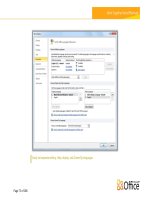
NAC Appliance Configuration Considerations
4-6
NAC Appliance Initial Configuration
4-7
NAC Appliance Switch Connectivity
4-7
NAC Appliance HA Server Configuration
4-8
Self-Signed Certificate for HA Deployment
4-10
Standalone WLAN Controller Deployment with NAC Appliance
4-11
WLC Port and Interface Configuration
4-13
AP Manager Interfaces
4-13
WLAN Client Interfaces
4-15
Contents
vi
Secure Wireless Design Guide 1.0
OL-13990-01
Mapping WLANs to Untrusted WLC Interfaces
4-16
WiSM Deployment with NAC Appliance
4-17
WiSM Backplane Switch Connectivity
4-18
WiSM Interface Configuration
4-20
WiSM WLAN Interface Assignment
4-20
Clean Access Manager/NAC Appliance Configuration Guidelines
4-20
Adding an HA NAC Pair to the CAM
4-20
Adding a Single NAC Appliance to the CAM
4-22
Connecting the Untrusted Interfaces (HA Configuration)
4-22
Adding Managed Networks
4-22
VLAN Mapping
4-24
DHCP Pass-through
4-24
Enabling Wireless Single Sign-On
4-25
NAC—Configuring VPN Authentication for Wireless SSO
4-26
Radius Proxy Accounting (Optional)
4-27
WLAN Controller—Configuring RADIUS Accounting for Wireless SSO
4-28
Creating a Wireless User Role
4-30
Defining an Authentication Server for Wireless Users Role
4-33
Defining User Pages
4-35
Configure Clean Access Method and Policies
4-38
End User Example—Wireless Single Sign-On
4-41
CHAPTER
5
Cisco Unified Wireless Firewall Integration
5-1
Role of the Firewall
5-1
Alternatives to an Access Edge Firewall
5-2
Protection against Viruses and Worms
5-3
Applying Guest Access Policies
5-3
Firewall Integration
5-4
FWSM
5-4
Routed versus Transparent
5-4
Single or Multiple Context
5-6
Basic Topology
5-6
Example Scenario
5-8
Department Partitioning
5-8
ACS RADIUS Configuration
5-9
WLC Configuration
5-11
FWSM Configuration
5-14
Security Contexts
5-27
High Availability
5-27
Contents
vii
Secure Wireless Design Guide 1.0
OL-13990-01
Spanning Tree and BPDUs
5-28
WLAN Client Roaming and Firewall State
5-29
Layer 2 and Layer 3 Roaming
5-30
Architectural Impact of Symmetric Layer 3
5-32
Configuration Changes for Symmetric Layer 3 Roaming
5-34
Layer 3 Roaming is not Mobile IP
5-34
Software Versions in Testing
5-35
CHAPTER
6
CSA for WLAN Security
6-1
CSA for WLAN Security Overview
6-1
CSA for General Client Protection
6-1
CSA for WLAN-Specific Scenarios
6-2
CSA and Complementary WLAN Security Features
6-4
CSA Integration with the Cisco Unified Wireless Network
6-4
Wireless Ad-Hoc Connections
6-5
Wireless Ad-hoc Networks—Security Concerns
6-6
CSA Wireless Ad-Hoc Connections Pre-Defined Rule Module
6-7
Pre-Defined Rule Module Operation
6-7
Pre-Defined Rule Module Operational Considerations
6-8
Pre-Defined Rule Module Configuration
6-9
Pre-Defined Rule Module Logging
6-11
Wireless Ad-Hoc Rule Customization
6-12
Simultaneous Wired and Wireless Connections
6-13
Simultaneous Wired and Wireless Connections—Security Concerns
6-13
CSA Simultaneous Wired and Wireless Connections Pre-Defined Rule Module
6-14
Pre-Defined Rule Module Operation
6-14
Pre-Defined Rule Module Operational Considerations
6-15
Pre-Defined Rule Module Configuration
6-16
Pre-Defined Rule Module Logging
6-19
Simultaneous Wired and Wireless Rule Customization
6-20
Location-Aware Policy Enforcement
6-21
Security Risks Addressed by Location-Aware Policy Enforcement
6-22
CSA Location-Aware Policy Enforcement
6-23
Location-Aware Policy Enforcement Operation
6-23
Location-Aware Policy Enforcement Configuration
6-26
General Location-Aware Policy Enforcement Configuration Notes
6-31
CSA Force VPN When Roaming Pre-Defined Rule Module
6-32
Pre-Defined Rule Module Operation
6-32
Pre-Defined Rule Module Operational Considerations
6-33
Contents
viii
Secure Wireless Design Guide 1.0
OL-13990-01
Pre-Defined Rule Module Configuration
6-34
Upstream QoS Marking Policy Enforcement
6-38
Benefits of Upstream QoS Marking
6-39
Benefits of Upstream QoS Marking on a WLAN
6-40
Challenges of Upstream QoS Marking on a WLAN
6-40
CSA Trusted QoS Marking
6-40
Benefits of CSA Trusted QoS Marking on a WLAN Client
6-42
Basic Guidelines for Deploying CSA Trusted QoS Marking
6-42
CSA Wireless Security Policy Reporting
6-42
CSA Management Center Reports
6-42
Third-Party Integration
6-45
Overall Deployment Guidelines for CSA Integrated WLAN Security
6-46
CSA Overview
6-46
CSA Solution Components
6-47
Sample Customized Wireless Ad-Hoc Rule Module
6-47
Sample Customized Rule Module Operation
6-47
Sample Customized Rule Module Definition
6-48
Sample Customized Rule Module Logging
6-55
Sample Customized Simultaneous Wired and Wireless Rule Module
6-56
Sample Customized Rule Module Operation
6-56
Sample Customized Rule Module Definition
6-58
Sample Customized Rule Module Logging
6-64
Test Bed Hardware and Software
6-65
References
6-65
CHAPTER
7
Cisco Unified Wireless Solution and IPS Integration
7-1
Roles of Wireless and Traditional IDS/IPS in WLAN Security
7-1
Complementary Role of Cisco Wireless and Traditional IDS/IPS
7-2
Collaborative Role of Cisco Wireless and Traditional IDS/IPS
7-3
Cisco WLC and IPS Integration Operation
7-5
Cisco WLC and IPS Synchronization
7-5
Activation of a WLAN Client Block from a Cisco IPS
7-6
Retraction of a WLAN Client Block
7-7
WLAN Client Block Operational Information
7-8
Cisco WLC and IPS Integration Implementation
7-9
WLC and IPS Integration Dependencies
7-9
Software
7-9
IPS Platform
7-9
Contents
ix
Secure Wireless Design Guide 1.0
OL-13990-01
IPS Deployment Model
7-9
Enabling Cisco WLC and IPS Integration
7-10
Verifying Cisco WLC and IPS Integration
7-15
Activating a WLAN Client Block from a Cisco IPS
7-16
WLAN Client Block Logging
7-20
SNMP Logging
7-20
Enabling SNMP Traps for WLAN Client Block Events
7-20
Viewing SNMP Traps for WLAN Client Block Events
7-23
WLC Local Logging
7-25
Enabling WLC Local Logging for WLAN Client Block Events
7-25
Viewing WLC Local Logs for WLAN Client Block Events
7-26
Cross-WLC WLAN Client Block Reporting Using WCS
7-28
Enabling Cross-WLC Reporting of WLAN Client Block Events Using WCS
7-28
Viewing Cross-WLC WLAN Client Block Events on WCS
7-28
General Guidelines for Cisco Wireless and Traditional IDS/IPS Deployment
7-32
Cisco IPS Overview
7-33
IPS Block versus Deny Actions
7-33
Test Bed Hardware and Software
7-34
References
7-34
CHAPTER
8
Deploying and Operating a Secure Wireless Network
8-1
Planning and Design Services
8-2
Cisco Wireless LAN Scoped Architectural and Security Design Service
8-2
Cisco Wireless LAN Scoped RF Assessment Service
8-2
Cisco Security Posture Assessment Services
8-2
Cisco Security Design Service
8-2
Implementation Services
8-2
Wireless LAN Implementation
8-3
Cisco Wireless LAN Scoped Configuration Service
8-3
Cisco Wireless LAN Scoped Post-deployment Validation Service
8-3
Security Implementation
8-3
Operate Services
8-3
Optimization Services
8-4
Benefits
8-4
Reference
8-4
G
LOSSARY
xi
Secure Wireless Design Guide 1.0
OL-13990-01
Preface
The purpose of this document is to discuss the Cisco Unified Wireless Solution security features and
their integration with the Cisco Self Defending Network.
Document Organization
The following table lists and briefly describes the chapters of this guide.
Section Description
Chapter 1, “802.11 Security
Summary.”
Describes the security features native to the 802.11 standards.
Chapter 2, “Cisco Unified
Wireless Network Architecture—
Base Security Features.”
Describes the security features native to the Cisco Unified
Wireless Solution.
Chapter 3, “Cisco Unified
Wireless/NAC Appliance
Integration Overview.”
Describes the Cisco NAC Appliance and its deployment in the
Cisco Unified Wireless Solution.
Chapter 4, “Cisco Unified
Wireless/NAC Appliance
Configuration.”
Describes the Cisco NAC Appliance configuration for integration
with the Cisco Unified Wireless Solution.
Chapter 5, “Cisco Unified
Wireless Firewall Integration.”
Describes the integration of the Cisco Unified Wireless Solution
with Cisco Firewall Solutions.
Chapter 6, “CSA for WLAN
Security.”
Describes the CSA v5.2 WLAN security features.
Chapter 7, “Cisco Unified
Wireless Solution and IPS
Integration.”
Describes the integration of the Cisco Unified Wireless Solution
with Cisco IPS solutions.
Chapter 8, “Deploying and
Operating a Secure Wireless
Network.”
Provides guidelines for deploying and operating a secure wireless
network.
CHAPTER
1-1
Secure Wireless Design Guide 1.0
OL-13990-01
1
802.11 Security Summary
This chapter discusses 802.11 security for customers currently investigating an enterprise wireless LAN
(WLAN) deployment. This chapter focuses on the most current enterprise security features that are
currently available for 802.11 wireless networks. For example, this guide focuses on methods such as
Wi-Fi Protected Access (WPA) and WPA2, and spends little time on Wired Equivalent Privacy (WEP).
Regulation, Standards, and Industry Certifications
As with most networking systems, various standards apply, which most often come from one of two
different standards bodies: the Institute of Electrical and Electronics Engineers (IEEE) and the Internet
Engineering Task Force (IETF). The 802.11 standards defined by the IEEE and the Extensible
Authentication Protocol (EAP) methods defined by the IETF are two of the core standards introduced in
support of secure WLAN deployments.
IEEE
The IEEE defines the 802.11 group of standards. The original 802.11 standard was published in 1999.
Subsequent amendments include adding physical layer implementations and providing greater bit rates
(802.11b, 802.11a, and 802.11g), adding QoS enhancements (802.11e), and adding security
enhancements (802.11i). This guide focuses on the security enhancements in 802.11i.
The IEEE also defines the 802.1X standard for port security, which is used in 802.11i for authentication
of WLAN clients.
IETF
The main IETF RFCs and drafts associated with 802.11 are based on EAP. The advantage of EAP is that
it decouples the authentication protocol from its transport. EAP can be carried in 802.1X frames, PPP
frames, UDP packets, or RADIUS sessions.
In 802.11 networks, EAP is transported across the WLAN in 802.1X frames, and from the Wireless LAN
Controller (WLC) to the Authentication, Authorization, and Accounting (AAA) server in the RADIUS
protocol, thus providing end-to-end EAP authentication between the WLAN client and the AAA server.
This is discussed in more detail later in this guide.
1-2
Secure Wireless Design Guide 1.0
OL-13990-01
Chapter 1 802.11 Security Summary
Regulation, Standards, and Industry Certifications
Wi-Fi Alliance
It is typical in core networks to find multiple single-vendor platforms whose integration together has
largely been achieved as part of product testing by the vendor. However, in cases where various vendor
platforms are being integrated, it is usually the responsibility of network engineers/administrators to
understand the capabilities of each device with regard to interoperability with other vendor devices.
When systems involve client devices, such as in WLANs, it is common for industry bodies to be formed
to certify interoperability because the standards often leave room for interpretation by vendors that might
also specify optional features. By certifying basic device behavior, customers are given a reasonable
level of assurance that two devices from different vendors will be interoperable.
The Wi-Fi Alliance () is an industry body that certifies WLAN device
interoperability through its Wi-Fi, Wi-Fi Protected Access (WPA), Wi-Fi Protected Access 2 (WPA2),
and Wi-Fi Multimedia (WMM) certification programs.
The WPA standard was developed to address the weakness in the WEP encryption process, which existed
before the ratification of the 802.11i workgroup standard. One of the key goals in the development of
WPA was to ensure backward compatibility with WEP-based hardware. To that end, the WPA standard
still uses the base RC4 encryption method used in WEP, but adds keying enhancements and message
integrity check improvements to address the weaknesses in WEP.
WPA2 is based on the ratified 802.11i standard, and uses Advanced Encryption Standard-Counter Mode
with Cipher Block Chaining Message Authentication Code Protocol (AES CCMP) encryption at its core.
WPA2 requires new client and AP hardware. Given current upgrade cycles for laptops and other client
devices, it can be expected that a mixture of WPA and WPA2 environments will co-exist for some time.
In a green field enterprise deployment, it is expected that customers will deploy WPA2 devices from the
start.
Cisco Compatible Extensions
The Cisco Compatible Extensions (CCX) program helps promote the widespread availability of client
devices that are interoperable with a Cisco WLAN infrastructure, and takes advantage of Cisco-specific
innovations for enhanced security, mobility, quality of service (QoS), and network management.
The CCX extensions build on the 802.11 and IETF standards, in addition to Wi-Fi Alliance certifications
to create a superset of WLAN features, as shown in
Figure 1-1. Even if a customer is not planning to
deploy a Cisco Unified Wireless Network, the use of CCX-compatible cards is a wise choice because it
offers a simple way of tracking the standards supported and certifications associated with WLAN client
devices.
Figure 1-1 CCX Structure
Table 1-1 shows a summary of the security features associated with each CCX certification level. The
CCX certification not only specifies which Wi-Fi certifications are applicable, but also which EAP
supplicants have been tested as part of the CCX certification.
CCX
Vendor Certification
Industry Certification
Standards Bodies
Spectrum Regulations
IETF
WiFi
FCC
IEEE
221272
1-3
Secure Wireless Design Guide 1.0
OL-13990-01
Chapter 1 802.11 Security Summary
Regulation, Standards, and Industry Certifications
The complete CCX version table can be found at the following URL:
/>s.html
Ta b l e 1-1 CCX Security Features Example
CCX v5 provides additional security features such as client-side management frame protection (MFP),
which is described in
Management Frame Protection, page 2-14.
Federal Wireless Security Policy and FIPS Certification
The mission-critical nature of the United States Department of Defense (DoD) requires it to have
exacting standards for wireless security. DoD security policy establishes the overall benchmark for
federal and civilian deployments as well as influences the security direction adopted by the commercial
enterprise market. These stringent DoD wireless security requirements are outlined in DoD Directive
8100.2: “Use of Commercial WLAN Devices, Systems, and Technologies in the Department of Defense
(DoD) Global Information Grid (GIG)”, June 2006. The following is an excerpt of that document:
(1) WLAN authentication and encryption. Starting in FY 2007 for all new acquisitions, DoD components must
implement WLAN solutions that are IEEE 802.11i compliant and are WPA2 Enterprise certified, that
implement 802.1X access control with EAP-TLS mutual authentication, and a configuration that ensures the
exclusive use of FIPS 140-2 minimum overall Level 1 validated Advanced Encryption Standard-Counter with
Cipher Block Chaining-Message Authentication Code Protocol (AES-CCMP) communications. Migration
Security
WEP
IEEE 802.1X
IEEE 802.11i–WPA2: 802.1X + AES
Network Admission Control (NAC)
Cisco TKIP (encryption)
WiFi Protected Access (WPA): 802.1X + WPA TKIP
LEAP
EAP-FAST
EAP-TLS ASD requires either LEAP, EAP-Fast, or EAP-TLS
With LEAP (ASD requires either LEAP, EAP-Fast, or EAP-TLS)
With EAP-FAST (ASD requires either LEAP, EAP-Fast, or EAP-TLS)
With EAP-TLS (ASD requires either LEAP, EAP-Fast, or EAP-TLS)
With PEAP-GTC
With LEAP
With PEAP-GTC
With PEAP-MSCHAP and EAP-TLS
With EAP-FAST
With PEAP-MSCHAP
PEAP with EAP-GTC (PEAP-GTC)
PEAP with EAP-MSCHAPv2 (PEAP-MSCHAP)
v1 v2 v3 v4 ASD
xxxx
xxxx x
x
x
xxx x
xxx
xxx
x
xx
xx
xx
xx
xx
x
x
x
x
xx
xx
x
x
xx
xxx
xxx
optional
221405
1-4
Secure Wireless Design Guide 1.0
OL-13990-01
Chapter 1 802.11 Security Summary
Regulation, Standards, and Industry Certifications
plans for legacy WLAN systems that do not support a Wi-Fi Alliance WPA2 certified 802.11i implementation
with a FIPS 140-2 validated cryptographic module must be reported to the DoD CIO within 180 days of this
policy memorandum, per paragraph 3.c.(2).
The 8100.2 directive references four key policy areas that are mandatory for all commercial WLAN
installations within DoD networks:
•
Standards-based IEEE 802.11i security (WPA2)
•
Interoperable Wi-Fi certified products
•
Wireless intrusion detection with location sensing
•
Federal Information Processing Standard (FIPS) 140-2 and Common Criteria certifications
FIPS 140-2 certification is required for all federal (civilian and DoD) WLAN product acquisitions. Cisco
Unified Wireless LAN Controllers and Access Points have received National Institute of Standards and
Technology (NIST) FIPS 140-2 level 2 certification for compliance with IEEE 802.11i WLAN security
standards. FIPS certification ensures that all cryptographic functions and operations within a given
crypto-module are implemented correctly. In the case of 802.11i (WPA2) security, this includes the
correct implementation and use of AES-CCMP for strong wireless encryption.
The Cisco Unified Wireless Network solution is also in the process of achieving Common Criteria
validation as mandated by the DoD wireless policy. Common Criteria validates the information
assurance (IA) aspect of an entire end-to-end WLAN system. This includes data protection for all
information that passes through and is stored in the system, strong authentication and access control,
intrusion detection, and system monitoring. The Cisco Common Criteria solution includes all critical
WLAN components, including the following:
•
WLAN Controllers
•
Aironet Access Points
•
Wireless Control System (WCS)
•
Access Control Server (ACS)
•
Wireless Location Appliance
The DoD policy document also discusses the requirements for strong authentication and wireless
intrusion detection with location sensing, which are discussed later in this guide, and subsequent
documents discussing threat containment and control.
In summary:
•
Cisco Unified Wireless is certified to meet the stringent wireless security requirements of the United
States government.
•
Cisco Unified Wireless ships with FIPS and Common Criteria integrated into the mainline software
and factory hardware.
•
Cisco Unified Wireless complies with the DoD end-to-end security requirements (trusted network
devices).
•
Cisco Unified Wireless meets DoD requirement for “continuous Wireless IDS monitoring with
location tracking” for wired and wireless networks.
•
Cisco ACS 4.1 is currently undergoing the FIPS certificate process.
1-5
Secure Wireless Design Guide 1.0
OL-13990-01
Chapter 1 802.11 Security Summary
Base 802.11 Security Features
Federal Communications Commission
The Federal Communications Commission (FCC) is the regulatory body controlling the radio frequency
(RF) spectrum used by WLANs in the United States. The FCC not only sets the rules for radio power
and antenna gain in the WLAN spectrum, but is also able to prosecute for breaches of its regulations.
For example, an extract of the relevant FCC regulations state the following:
•
Section 15.5—General conditions of operation.
(a) Persons operating intentional or unintentional radiators shall not be deemed to have any vested
or recognizable right to continued use of any given frequency by virtue of prior registration or
certification of equipment, or, for power line carrier systems, on the basis of prior notification of use
pursuant to Section 90.63(g) of this chapter. [Should reference Section 90.35(g).]
(b) Operation of an intentional, unintentional, or incidental radiator is subject to the conditions that
no harmful interference is caused and that interference must be accepted that may be caused by the
operation of an authorized radio station, by another intentional or unintentional radiator, by
industrial, scientific, and medical (ISM) equipment, or by an incidental radiator.
(c) The operator of a radio frequency device shall be required to cease operating the device upon
notification by a Commission representative that the device is causing harmful interference.
Operation shall not resume until the condition causing the harmful interference has been corrected.
•
Section 15.9—Prohibition against eavesdropping.
Except for the operations of law enforcement officers conducted under lawful authority, no person
shall use, either directly or indirectly, a device operated pursuant to the provisions of this Part for
the purpose of overhearing or recording the private conversations of others unless such use is
authorized by all of the parties engaging in the conversation.
Therefore, although the 802.11 radio spectrum is unlicensed, it is regulated, and legal recourse is
available in the case of abuse of the spectrum or the unlawful actions.
Base 802.11 Security Features
This chapter focuses on the enterprise security features that are currently available for 802.11 wireless
networks.
Although there were initially security flaws native to the 802.11 protocol, the introduction of 802.11i
has addressed all the known data privacy issues, which are to ensure that the requirements for
confidential communications are achieved through the use of strong authentication and encryption
methods.
Additional WLAN security issues are discussed later in this guide. Some of these issues are being
addressed by standards bodies, while others are being addressed in the Cisco Unified Wireless Network
Solution.
Terminology
A number of common terms are introduced throughout this guide, and are shown in Figure 1-2.
1-6
Secure Wireless Design Guide 1.0
OL-13990-01
Chapter 1 802.11 Security Summary
Base 802.11 Security Features
Figure 1-2 Secure Wireless Topology
The basic physical components of the solution are as follows:
•
WLAN client
•
Access point (AP)
•
Wireless LAN Controller (WLC)
•
AAA server
Figure 1-2 also shows the basic roles and relationships associated with the 802.1X authentication
process:
•
An 802.1X supplicant resides on the WLAN client.
•
The AP and WLC, using the split-MAC architecture, act together as the 802.1X authenticator.
•
The AAA server is the authentication server.
Figure 1-2 also illustrates the role of 802.1X and the RADIUS protocol in carrying EAP packets between
the client and the authentication server. Both 802.1X and EAP are discussed in more detail later in this
chapter.
802.11 Fundamentals
802.11 WLANs consist of multiple elements and behaviors, which make up the foundation of the 802.11
protocol. A key part of the protocol discovers the appropriate WLAN and establishes a connection with
that WLAN. The primary components of this process are as follows:
•
Beacons—Used by the WLAN network to advertise its presence
•
Probes—Used by WLAN clients to find their networks
•
Authentication—An artifact from the original 802.11 standard
•
Association—Establishes the data link between an AP and a WLAN client
Although beacons are regularly broadcast by an AP, the probe, authentication, and association frames
are generally used only during the association and re-association process.
LWAPP
RADIUS
RADIUS
EAP
Supplicant
Encryption
WLAN Client
Authenticator
Enterprise Network
Wireless LAN
Controller
Access Point
LWAPP
Authentication
Server
AAA Server
802.1x
221272
1-7
Secure Wireless Design Guide 1.0
OL-13990-01
Chapter 1 802.11 Security Summary
Base 802.11 Security Features
802.11 Beacons
The following example shows a portion of a WLAN beacon decode for the WLAN network called wpa1.
In this beacon, you can see the service set identifier (the network name), the supported bit rates, and the
security implementation for that WLAN.
The primary purpose of the beacon is to allow WLAN clients to learn which networks and APs are
available in a given area, thereby allowing them to choose which network and AP to use.
Note
Many WLAN security documents suggest that sending beacons without the service set identifier (SSID)
is a security best practice that prevents potential hackers from learning the SSID of a WLAN network.
All enterprise WLAN solutions offer this as an option. However, given that the SSID can be easily
discovered while sniffing a WLAN client during the association phase, this option has little security
value. For operational and client support issues, it is often better to allow the SSID to be broadcast. The
SSID chosen should be relatively obscure with regard to the identity of the company or the purpose of
the WLAN, while at the same time being as unique as possible; the SSID should not give away the
purpose or the owner of the WLAN. Creating long random strings as SSIDs is not recommended because
this simply adds to the operations and maintenance overhead without an appreciable security
improvement; a simple word is often the best choice. Common WLAN-related words should be avoided
because there is no process or standard to prevent accidental or intentional SSID duplication.
The following is an 802.11 beacon example:
Type/Subtype: Beacon frame (8)
…
Destination address: Broadcast (ff:ff:ff:ff:ff:ff)
…
Sequence number: 2577IEEE 802.11 wireless LAN management frame
…
SSID parameter set: "wpa1"
Tag Number: 0 (SSID parameter set)
Tag length: 4
Tag interpretation: wpa1
Supported Rates: 1.0 2.0 5.5 11.0(B) 6.0 9.0 12.0 18.0
Tag Number: 1 (Supported Rates)
Tag length: 8
Tag interpretation: Supported rates: 1.0 2.0 5.5 11.0(B) 6.0 9.0 12.0 18.0
[Mbit/sec]
…
Vendor Specific: WPA
Tag Number: 221 (Vendor Specific)
Tag length: 28
Tag interpretation: WPA IE, type 1, version 1
Tag interpretation: Multicast cipher suite: TKIP
Tag interpretation: # of unicast cipher suites: 2
Tag interpretation: Unicast cipher suite 1: TKIP
Tag interpretation: # of auth key management suites: 1
Tag interpretation: auth key management suite 1: WPA
Tag interpretation: Not interpreted
…
1-8
Secure Wireless Design Guide 1.0
OL-13990-01
Chapter 1 802.11 Security Summary
Base 802.11 Security Features
802.11 Join Process (Association)
Before an 802.11 client can send data over a WLAN network (Fast Roaming is an exception to this
process, but is not discussed in this guide), it goes through the following three-stage process:
•
802.11 probing—802.11 networks make use of a number of options, but for an enterprise
deployment, the search for a specific network involves sending a probe request out on multiple
channels that specifies the network name (SSID) and bit rates.
•
802.11 authentication—802.11 was originally developed with two authentication mechanisms. The
first one, called “open authentication”, is fundamentally a NULL authentication where the client
says “authenticate me”, and the AP responds with “yes”. This is the mechanism used in almost all
802.11 deployments.
A second authentication mechanism is based on a shared WEP key, but the original implementation
of this authentication method is flawed. Although it needs to be included for overall standards
compliance, it is not used or recommended.
Open authentication is the only method used in enterprise WLAN deployments, and as previously
mentioned, it is fundamentally a NULL authentication, Therefore, “real authentication” is achieved
by using 802.1X/EAP authentication mechanisms.
•
802.11 association—This stage finalizes the security and bit rate options, and establishes the data
link between the WLAN client and the AP.
A typical secure enterprise WLAN AP blocks WLAN client traffic at the AP until a successful 802.1X
authentication.
If a client has joined a network and roams from one AP to another within the network, the association is
called a re-association. The primary difference between an association and a re-association event is that
a re-association frame sends the MAC address (BSSID) of the previous AP in its re-association request
to provide roaming information to the extended WLAN network.
Probe Request and Probe Response
A typical WLAN client supplicant is configured with a desired WLAN network, which means that probe
requests from the WLAN client contain the SSID of the desired WLAN network. This is sent “in the
clear”, as are all the association messages, thereby making it relativity easy for a WLAN sniffer to
identify which SSIDs are active in an area.
If the WLAN client is simply trying to discover the available WLAN networks, it can send out a probe
request with no SSID, and all APs that are configured to respond to this type of query will respond.
Note
WLANs without Broadcast SSID enabled do not respond.
The following shows a segment of a sample probe request, where the WLAN client sends out a request
for a particular SSID (wpa1).
IEEE 802.11 wireless LAN management frame
Tagged parameters (31 bytes)
SSID parameter set: "wpa1"
...
Supported Rates: 1.0(B) 2.0(B) 5.5 11.0 6.0 9.0 12.0 18.0
...
Extended Supported Rates: 24.0 36.0 48.0 54.0
...
1-9
Secure Wireless Design Guide 1.0
OL-13990-01
Chapter 1 802.11 Security Summary
Base 802.11 Security Features
The following shows a portion of a sample probe response, where an AP using the specified SSID
responds with supported rate and security properties for that WLAN SSID.
…
IEEE 802.11 wireless LAN management frame
…
Tag Number: 1 (Supported Rates)
Tag length: 8
Tag interpretation: Supported rates: 1.0 2.0 5.5 11.0(B) 6.0 9.0 12.0 18.0
[Mbit/sec]
…
Tag interpretation: WPA IE, type 1, version 1
Tag interpretation: Multicast cipher suite: TKIP
Tag interpretation: # of unicast cipher suites: 1
Tag interpretation: Unicast cipher suite 1: TKIP
Tag interpretation: # of auth key management suites: 1
Tag interpretation: auth key management suite 1: WPA
Tag interpretation: Not interpreted
…
Authentication
The following samples show an “open” authentication request and response frame, respectively. As can
be seen from the decodes, no authentication data is transferred.
•
WLAN client authentication request
…
Type/Subtype: Authentication (11)
…
IEEE 802.11 wireless LAN management frame
Fixed parameters (6 bytes)
Authentication Algorithm: Open System (0)
Authentication SEQ: 0x0001
Status code: Successful (0x0000)
•
AP authentication response
…
Type/Subtype: Authentication (11)
…
IEEE 802.11 wireless LAN management frame
Fixed parameters (6 bytes)
Authentication Algorithm: Open System (0)
Authentication SEQ: 0x0002
Status code: Successful (0x0000)
Another frame type related to authentication frames is the de-authentication frame, which when sent to
a WLAN client causes the client to disconnect from the AP to which the client is currently connected.
This may cause a WLAN client to go through the entire probe request process again, or at least make it
restart the authentication/association process. De-authentication frames can be sent to the broadcast
MAC address and cause the disconnection of every client associated with the AP sending that frame, but
many current WLAN clients ignore multicast de-authentication frames, diminishing the potential scale
of this type of attack.
Given that a de-authentication frame can be spoofed, it can be used by attackers to create a
denial-of-service (DoS) attack on an AP, or to force clients to reassociate, thereby allowing an attack to
occur on a client in a known state. This is one of the reasons why Cisco developed management frame
protection (MFP), as part of the CCX feature set. MFP is discussed in more detail in
Management Frame
Protection, page 2-14.
1-10
Secure Wireless Design Guide 1.0
OL-13990-01
Chapter 1 802.11 Security Summary
Base 802.11 Security Features
Association
In the following traces, the final bit rates and security parameters are agreed upon at the association
request and response frames. After this is successfully completed, 802.11 data frames can be sent
between the WLAN client and the WLAN AP. In an enterprise WLAN deployment, these data frames
are limited to 802.1X frames between the WLAN client and the AP until 802.1X/EAP authentication is
completed and successful.
•
WLAN client association request
…
Type/Subtype: Association Request (0)
Frame Control: 0x0000 (Normal)
Duration: 314
Destination address: Airespac_52:42:d9 (00:0b:85:52:42:d9)
Source address: IntelCor_7c:a3:47 (00:12:f0:7c:a3:47)
BSS Id: Airespac_52:42:d9 (00:0b:85:52:42:d9)
Fragment number: 0
Sequence number: 90
Frame check sequence: 0x1f17420d [correct]
IEEE 802.11 wireless LAN management frame
Fixed parameters (4 bytes)
Capability Information: 0x0431
Listen Interval: 0x000a
Tagged parameters (48 bytes)
SSID parameter set: "wpa1"
Tag Number: 0 (SSID parameter set)
Tag length: 4
Tag interpretation: wpa1
Supported Rates: 1.0 2.0 5.5 11.0(B) 6.0 9.0 12.0 18.0
Tag Number: 1 (Supported Rates)
Tag length: 8
Tag interpretation: Supported rates: 1.0 2.0 5.5 11.0(B) 6.0 9.0 12.0 18.0
[Mbit/sec]
Vendor Specific: WPA
Tag Number: 221 (Vendor Specific)
Tag length: 24
Tag interpretation: WPA IE, type 1, version 1
Tag interpretation: Multicast cipher suite: TKIP
Tag interpretation: # of unicast cipher suites: 1
Tag interpretation: Unicast cipher suite 1: TKIP
Tag interpretation: # of auth key management suites: 1
Tag interpretation: auth key management suite 1: WPA
Tag interpretation: Not interpreted
Extended Supported Rates: 24.0 36.0 48.0 54.0
Tag Number: 50 (Extended Supported Rates)
Tag length: 4
Tag interpretation: Supported rates: 24.0 36.0 48.0 54.0 [Mbit/sec]
•
AP association response
…
Type/Subtype: Association Response (1)
Frame Control: 0x0010 (Normal)
Duration: 213
Destination address: IntelCor_7c:a3:47 (00:12:f0:7c:a3:47)
Source address: Airespac_52:42:d9 (00:0b:85:52:42:d9)
BSS Id: Airespac_52:42:d9 (00:0b:85:52:42:d9)
Fragment number: 0
Sequence number: 1001
Frame check sequence: 0x759406b6 [correct]
IEEE 802.11 wireless LAN management frame
1-11
Secure Wireless Design Guide 1.0
OL-13990-01
Chapter 1 802.11 Security Summary
Base 802.11 Security Features
Fixed parameters (6 bytes)
Capability Information: 0x0431
Status code: Successful (0x0000)
Association ID: 0x0001
Tagged parameters (47 bytes)
Supported Rates: 1.0 2.0 5.5 11.0(B) 6.0 9.0 12.0 18.0
Tag Number: 1 (Supported Rates)
Tag length: 8
Tag interpretation: Supported rates: 1.0 2.0 5.5 11.0(B) 6.0 9.0 12.0 18.0
[Mbit/sec]
Extended Supported Rates: 24.0 36.0 48.0 54.0
Tag Number: 50 (Extended Supported Rates)
Tag length: 4
Tag interpretation: Supported rates: 24.0 36.0 48.0 54.0 [Mbit/sec]
Vendor Specific: Aironet Unknown
Tag Number: 221 (Vendor Specific)
Tag length: 29
Aironet IE type: Unknown (12)
Aironet IE data: 02C1257CF1AA1E0D010000A80200000000494C9788132233...
The association process also has a related disassociation frame that can be used to disconnect WLAN
clients from their AP. The disassociation frame can be only a unicast frame, and is therefore less likely
to be used in a DoS attack, but could still be used to cause clients to re-associate, thereby allowing a DoS
attack or an attack on the client to begin in a known state.
802.1X
802.1X is an IEEE framework for port-based access control that has been adopted by the 802.11i security
workgroup as a means of providing authenticated access to WLAN networks.
•
The 802.11 association process creates a “virtual” port for each WLAN client at the AP.
•
The AP blocks all data frames apart from 802.1X-based traffic.
•
The 802.1X frames carry the EAP authentication packets, which are passed through to the AAA
server by the AP.
•
If the EAP authentication is successful, the AAA server sends an EAP success message to the AP,
where the AP then allows data traffic from the WLAN client to pass through the virtual port.
•
Before opening the virtual port, data link encryption between the WLAN client and the AP is
established to ensure that no other WLAN client can access the port that has been established for a
given authenticated client.
Extensible Authentication Protocol
Extensible Authentication Protocol (EAP) is an IETF RFC that stipulates that an authentication protocol
must be decoupled from the transport protocol used to carry it. This allows the EAP protocol to be
carried by transport protocols such as 802.1X, UDP, or RADIUS without having to make changes to the
authentication protocol itself.
The basic EAP protocol is relatively simple, consisting of the following four packet types:
•
EAP request—The request packet is sent by the authenticator to the supplicant. Each request has a
type field that indicates what is being requested; for example, supplicant identity and EAP type to
be used. A sequence number allows the authenticator and the peer to match an EAP response to each
EAP request.
1-12
Secure Wireless Design Guide 1.0
OL-13990-01
Chapter 1 802.11 Security Summary
Base 802.11 Security Features
•
EAP response—The response packet is sent by the supplicant to the authenticator, and uses a
sequence number to match the initiating EAP request. The type of the EAP response generally
matches the EAP request, except if the response is a negative-acknowledgment (NAK).
•
EAP success—The success packet is sent when successful authentication has occurred, and is sent
from the authenticator to the supplicant.
•
EAP failure—The failure packet is sent when unsuccessful authentication has occurred, and is sent
from the authenticator to the supplicant.
When using EAP in an 802.11i compliant system, the AP operates in EAP pass-through mode. In this
mode, it checks the code, identifier, and length fields, and then forwards EAP packets received from the
client supplicant to the AAA. EAP packets received by the authenticator from the AAA server are
forwarded to the supplicant.
Figure 1-3 shows an example of EAP protocol flow.
Figure 1-3 EAP Protocol Flow
Authentication
Depending on the customer requirements, various authentication protocols such as PEAP, EAP-TLS,
and EAP-FAST can be used in secure wireless deployments. Regardless of the protocol, they all
currently use 802.1X, EAP, and RADIUS as their underlying transport. These protocols allow network
access to be controlled based on the successful authentication of the WLAN client, and just as
importantly, allow the WLAN network to be authenticated by the user.
This solution also provides authorization through policies communicated through the RADIUS protocol,
as well as RADIUS accounting.
EAP types used for performing authentication are described in more detail below. The primary factor
affecting the choice of EAP protocol is the authentication system (AAA) currently in use. Ideally, a
secure WLAN deployment should not require the introduction of a new authentication system, but rather
should leverage the authentication systems that are already in place.
221274
LWAPP
Authentication conversation is between client and Authentication Server
RADIUS
Enterprise
Network
EAP Identity Request
EAP Identity Response
EAP Request – EAP Type
Forward Identify to ACS Server
EAP Response – EAP Type
EAP Response – EAP Type
EAP Request – EAP Type
EAP Success
EAP Success
802.1x
LWAPP
1-13
Secure Wireless Design Guide 1.0
OL-13990-01
Chapter 1 802.11 Security Summary
Base 802.11 Security Features
Supplicants
The client software used for WLAN authentication is called a supplicant, based on 802.1X terminology.
The Cisco Secure Services Client (CSSC) 4.1 is a supplicant that supports wired and wireless networks,
and all the common EAP types. Supplicants may also be provided by the WLAN NIC manufacturer, or
can come integrated within an operating system; for example, Windows XP supports PEAP MSCHAPV2
and EAP-TLS.
For more information on CSSC, see the following URL:
/>Figure 1-4 shows the logical location of the supplicant relative to the overall authentication architecture.
The role of the supplicant is to facilitate end-user authentication using EAP and 802.1X to an upstream
authenticator; in this case, the WLC. The authenticator forwards EAP messages received by the
supplicant and forwards them to an upstream AAA server using RADIUS.
Figure 1-4 WLAN Client Supplicant
The various EAP supplicants that are available in the marketplace reflect the diversity of authentication
solutions and customer priorities.
Table 1-2 shows a summary of common EAP supplicants:
•
PEAP MSCHAPv2—Protected EAP MSCHAPv2. Uses a Transport Layer Security (TLS) tunnel,
(the IETF standard of an SSL) to protect an encapsulated MSCHAPv2 exchange between the WLAN
client and the authentication server.
•
PEAP GTC—Protected EAP Generic Token Card (GTC). Uses a TLS tunnel to protect a generic
token card exchange; for example, a one-time password or LDAP authentication.
•
EAP-FAST—EAP-Flexible Authentication via Secured Tunnel. Uses a tunnel similar to that used in
PEAP, but does not require the use of Public Key Infrastructure (PKI).
•
EAP-TLS—EAP Transport Layer Security uses PKI to authenticate both the WLAN network and
the WLAN client, requiring both a client certificate and an authentication server certificate.
LWAPP
RADIUS
RADIUS
EAP
Supplicant
Encryption
WLAN Client
Authenticator
Enterprise Network
Wireless LAN
Controller
Access Point
LWAPP
Authentication
Server
AAA Server
802.1x
221275
LWAPP
RADIUS
RADIUS
EAP
yption
Authenticator
Enterprise Network
Wireless LAN
Controller
Access Point
LWAPP
n Autheentication
Server
AAAA Server
802.1x
y
1-14
Secure Wireless Design Guide 1.0
OL-13990-01
Chapter 1 802.11 Security Summary
Base 802.11 Security Features
Authenticator
The authenticator in the case of the Cisco Secure Wireless Solution is the Wireless LAN Controller
(WLC), which acts as a relay for EAP messages being exchanged between the 802.1X-based supplicant
and the RADIUS authentication server.
After the completion of a successful authentication, the WLC receives the following:
•
A RADIUS packet containing an EAP success message
•
An encryption key generated at the authentication server during the EAP authentication
•
RADIUS vendor-specific attributes
(
VSAs) for communicating policy
Figure 1-5 shows the logical location of the “authenticator” within the overall authentication
architecture. The authenticator controls network access using the 802.1X protocol, and relays EAP
messages between the supplicant and the authentication server.
Ta b l e 1-2 Comparison of Common Supplicants
Cisco
EAP-FAST
PEAP
MS-CHAPv2
PEAP EAP-GTC EAP-TLS
Single sign-on (MSFT AD only) Yes Yes Yes
1
1. Supplicant dependent
Yes
Login scripts (MSFT AD only) Yes Yes Some Yes
2
2. Machine account and machine authentication is required to support the scripts.
Password change (MSFT AD) Yes Yes Yes N/A
Microsoft AD database support Yes Yes Yes Yes
ACS local database support Yes Yes Yes Yes
LDAP database support Yes
3
3. Automatic provisioning is not supported on with LDAP databases.
No Yes Yes
OTP authentication support Yes
4
4. Supplicant dependent
No Yes No
RADIUS server certificate
required?
No Yes Yes Yes
Client certificate required? No No No Yes
Anonymity Yes Yes
5
5. Supplicant dependent
Yes
6
6. Supplicant dependent
No
1-15
Secure Wireless Design Guide 1.0
OL-13990-01
Chapter 1 802.11 Security Summary
Base 802.11 Security Features
Figure 1-5 Authenticator Location
Table 1-3 shows an example decode of an EAP-TLS authentication where the four left-most columns are
wireless 802.1X decodes, and the three right-most columns are decodes of the respective RADIUS
transactions for the same EAP-TLS authentication.
The EAP exchange sequence is as follows:
•
Packet #1 is sent by the AP to the client, requesting the client identity. This begins the EAP
exchange.
•
Packet #2 is the client identity that is forwarded to the RADIUS server. Based on this identity, the
RADIUS server can decide whether to continue with the EAP authentication.
•
In packet #3, the RADIUS server sends a request to use PEAP as the EAP method for authentication.
The actual request depends on the EAP types configured on the RADIUS server. If the client rejects
the PEAP request, the RADIUS server may offer other EAP types.
•
Packets #4–8 are the TLS tunnel setup for PEAP.
•
Packets #9–16 are the authentication exchange within PEAP.
•
Packet #17 is the EAP message saying that the authentication was successful.
In addition to informing the supplicant and authenticator that the authentication was successful,
packet #17 also carries encryption keys and authorization information to the authenticator.
LWAPP
RADIUS
RADIUS
EAP
Supplicant
Encryption
WLAN Client
Authenticator
Enterprise Network
Wireless LAN
Controller
Access Point
LWAPP
Authentication
Server
AAA Server
802.1x
221276
nAutheentication
Server
AAAA Server
Supplicant
Encry
WLAN Client
y
Ta b l e 1-3 EAP Transaction
# Source Dest Protocol Info Source Dest RADIUS Info
1 AP Client EAP “Request,” Identity
2 Client AP EAP “Response,” Identity WLC AAA “Access-Request(1)
(id=114, l=174)”
3 AP Client EAP “Request,” PEAP AAA WLC “Access-challenge(11)
(id=115, l=76)”
4 Client AP TLS
1
Client Hello WLC AAA “Access-Request(1)
(id=116, l=296)”
5 AP Client TLS Server “Hello,”
“Certificate,”
AAA WLC “Access-challenge(11)
(id=116, l=968)”