Tài liệu Clutches and brakes design and selection P5 docx
Bạn đang xem bản rút gọn của tài liệu. Xem và tải ngay bản đầy đủ của tài liệu tại đây (888.78 KB, 23 trang )
5
DryandWetDiskBrakesandClutches
Thischapterondiskbrakesandclutcheswillconsiderannularcontactdisk
clutchesandbothcaliperandannularcontactdiskbrakes,asillustratedin
Figures1,2,and3.
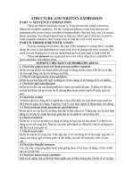
Caliper disk brakes, as shown in Figure 1, are used on aircraft, auto-
motive, industrial, and mining equipment. Their two main advantages com-
pared to drum brakes are greater heat dissipation, and hence less fading,
because of their open construction, and a more uniform braking action, due
to self-cleaning by brake pad abrasion. Their main disadvantage is that they
require a larger activation force than is required for drum brakes because they
have neither a friction moment nor servo action to aid in brake application.
Annular contact disk brakes and clutches are available as either dry
or wet brakes, as shown in Figure 2 and 3. These units may be used as either a
brake or as a clutch because the only differences between the two are whether
one side of the unit is fastened to a stationary frame or to a rotating shaft and
whether the unit has the necessary fittings for it to be controlled while in
rotation. For example, both of these functions are combined in Minster
combination dry clutch and brake units, illustrated in Figure 2, which are
pneumatically controlled using air passages in the shaft to the combination
unit.
Wet multiple-disk brakes and clutches, illustrated in Figure 3, have
similar multiple-disk construction, but operate in an oil bath. Thus these
brakes are isolated from dirt and water, and the circulation of the oil through
a heat exchanger usually provides greater heat dissipation than can be had
from direct air cooling. Because of these advantages, wet brakes have been
Copyright © 2004 Marcel Dekker, Inc.
used on large earth-moving equipment, on mine shuttle cars, and similar
equipment which may require large braking torque and which may be de-
signed to operate in a dirty environment.
I. CALIPER DISK BRAKES
From the moment of contact until the disk is stopped, the velocity of the disk
relative to the brake pads will vary linearly with the disk radius. If the thick-
ness of the lining material removed is denoted by y and if y is dependent on the
relative velocity and the pressure, as is commonly assumed, then according to
the uniform wear assumption,
y ¼ kpr ð1-1Þ
where k is a constant of proportionality. Since the caliper brake pads are
usually small enough for their supports to be considered rigid, we shall assume
F
IGURE
1 Floating, or sliding, caliper disk brake. (Courtesy of Misco, Inc., North
Mankato, MN.)
Chapter 584
Copyright © 2004 Marcel Dekker, Inc.
that y is constant over the brake pad (i.e., the wear is uniform). Whenever
these conditions hold, equation (1-1) implies that the pressure increases as the
radius decreases, so the maximum pressure is found at the inner radius, r
i
.
Thus
y ¼ kp
max
r
i
ð1-2Þ
Elimination of k and y from equations (1-1) and (1-2) yields
p ¼ p
max
r
j
r
ð1-3Þ
With the lining pressure known, we may now calculate the required axial force
from
F ¼
Z
A
pda ð1-4Þ
and the resulting braking torque from
T ¼ A
Z
A
pr da ð1-5Þ
F
IGURE
1 Continued.
Dry and Wet Disk Brakes and Clutches 85
Copyright © 2004 Marcel Dekker, Inc.
Evaluationoftheseintegralsiseasiestforbrakepadswithradialand
circularboundaries,asinFigure4,forwhichequation(1-4)and(1-5)maybe
writtenusingadummyvariablefas
F¼p
max
r
i
Z
A
1
r
da¼p
max
r
i
Z
r
0
r
i
Z
u
0
dfdrð1-6Þ
¼p
max
r
i
uðr
0
Àr
i
Þ
and
T¼Ap
max
r
i
Z
A
da¼Ap
max
r
i
Z
r
o
r
i
rdr
Z
u
0
df
ð1-7Þ
¼Ap
max
r
i
u
2
r
2
o
Àr
2
i
ÀÁ
Fromequation(1-7)wefindthatforthepressuredistributiongivenbyrela-
tion(1-3)thetorquemaybeeasilycalculatedforanybrakepadwhoseareais
F
IGURE
2Combinationdiskbrakeanddiskclutch,bothdry.(CourtesyofMinster
Machine Co., Minster, OH.)
Chapter 586
Copyright © 2004 Marcel Dekker, Inc.
F
IGURE
3 Wet multiple-disk brake. (Courtesy D. A. B. Industries, Inc., Troy, MI.)
Dry and Wet Disk Brakes and Clutches 87
Copyright © 2004 Marcel Dekker, Inc.
knownorsimplycalculated.Foracircularpadofdiameterd,forexample,the
torqueisgivenby
T¼Ap
max
r
i
k
4
d
2
ð1-8Þ
Accordingtoequation(1-7),thetorqueprovidedbyacaliperbrakehaving
padssimilartothoseinFigure4usuallywillbegreaterthanthatprovidedby
circularpadsofequalarea,asshowninFigure5,whenactingondisksofequal
outsidediameterbecausetheproportionsofthepadsinthebrakeshownin
Figure4generallyplacethecenterofpressureatalargerradiusfromthe
centerofthedisk.(SeealsoFigure6.)
Circularpadsareoftenused,nevertheless,inhydraulicallyactivated
caliperbrakeswheneverthehydraulicpressuremaybeincreasedrelatively
cheaplybecausethepadsthemselvesaresupportedentirelybythepiston
faceandarethereforecheapertoproducebecausenoadditionalsupporting
F
IGURE
4Annularsectorcaliperdiskbrake.(CourtesyofHortonManufacturing
Co., Inc., Minneapolis, MN.)
Chapter 588
Copyright © 2004 Marcel Dekker, Inc.
structure is required. Noncircular pads are used where increasing the pressure
may be relatively expensive and where the maximum performance is required
for the pressure that is available, as in aircraft brakes.
If we replace d
2
/4 in equation (1-8) with r
p
2
, where r
p
is the pad radius
(r
p
= d/2), and also replace r
i
in equation (1-8) according to the relation
r
i
= r
o
À 2r
p
,wehave
T ¼ Akp
max
ðr
o
À 2r
p
Þr
2
p
ð1-9Þ
Upon differentiating equation (1-9) with respect to r
p
we obtain
dT
dr
p
¼ Akp
max
2r
p
ðr
o
À 3r
p
Þð1-10Þ
which is equal to zero when r
p
= r
o
/3, indicating an extreme value of T for that
pad radius. Since dT
2
/dr
p
2
is negative at this value of r
p
, it follows that T has its
maximum value at r
p
= r
o
/3.
Calculating the activation force for a circular pad is more involved than
it is for an annular sector pad because radius r remains in the denominator of
F
IGURE
4 Continued.
Dry and Wet Disk Brakes and Clutches 89
Copyright © 2004 Marcel Dekker, Inc.
theintegrand.Anelementofthepadareamaybewrittenasda=UdUdu,
whereradiusUismeasuredfromthecenterofthepad,asshowninupcoming
Figure13,associatedwithlaterExample4.1.Complexityarisesfromthe
requirementthattheexpressionfortheradiusrfromthecenterofthediskto
theelementofareaofthecircularpadmustnowbewrittenintermsofUandu.
Fromthelawofcosineswehave
r¼ðr
2
c
þU
2
À2r
c
UcosuÞ
1=2
ð1-11Þ
wherer
c
istheradiusfromthecenterofthebrakepadtoelementalareada,as
showninFigure13(seelaterExample4.1).
Substitutionofequation(1-11)intothefirstintegralinequation(1-6)
andwritingtheelementofareaasUdUduallowstheactivationforcetobe
writtenas
F¼p
max
r
i
Z
2k
0
Z
r
p
0
U
ðU
2
þr
2
c
À2U
i
r
c
cosuÞ
1=2
dUduð1-12Þ
F
IGURE
5Caliperdiskbrakewithcircularpads,twopistons.(CourtesyofMisco,
Inc., North Mankato, MN.)
Chapter 590
Copyright © 2004 Marcel Dekker, Inc.
Since analytical evaluation of the integrals in equation (1-12) is somewhat
tedious, it is easier to turn to numerical methods. Evaluation using a numeri-
cal program, such as Mathcad, may provide graphical data that displays the
dependence of force F on the pad radius r
p
, as will be demonstrated later in
Example 4.1.
The Mathcad manual specifies the integration method used in its pro-
gram and the references used in writing the program. They may be consulted
for the details of mathematical analysis.
II. VENTILATED DISK BRAKES
Although disk brakes are less susceptible to fade than drum brakes, they will
be heated by friction, which may lead to brake fade in situations requiring
heavy and frequent braking. This heating may be reduced by using ventilated
F
IGURE
6 Typical caliper brake pad of sintered material for heavy aircraft brakes.
(Note contour of the pad to place lining material toward the outer periphery of the
disk.) (Courtesy Friction Products, Medina, OH.)
Dry and Wet Disk Brakes and Clutches 91
Copyright © 2004 Marcel Dekker, Inc.