Tài liệu Cutting Tools P3 pdf
Bạn đang xem bản rút gọn của tài liệu. Xem và tải ngay bản đầy đủ của tài liệu tại đây (497.06 KB, 10 trang )
Cutting
Tool
Applications
Cutting Tool Applications
By George Schneider, Jr. CMfgE
2
Tooling & Production/Chapter 3
www.toolingandproduction.com
3.1 Introduction
The condition and physical properties of the work material have a direct influence on the
machinability of a work material. The various conditions and characteristics described as
‘condition of work material’, individually and in combinations, directly influence and
determine the machinability. Operating conditions, tool material and geometry, and work-
piece requirements exercise indirect effects on machinability and can often be used to
overcome difficult conditions presented by the work material. On the other hand, they
can create situations that increase machining difficulty if they are ignored. A thorough
understanding of all of the factors affecting machinability and machining will help in
selecting material and workpiece designs to achieve the optimum machining combina-
tions critical to maximum productivity.
3.2 Condition of Work Material
The following eight factors determine the condition of the work material: microstructure,
grain size, heat treatment, chemical composition, fabrication, hardness, yield strength,
and tensile strength.
Microstructure: The microstructure of a metal refers to its crystal or grain structure
as shown through examination of etched and polished surfaces under a microscope.
Metals whose microstructures are similar have like machining properties. But there can
be variations in the microstructure of the same workpiece, that will affect machinability.
Grain Size: Grain size and structure of a metal serve as general indicators of its
machinability. A metal with small undistorted grains tends to cut easily and finish easi-
ly. Such a metal is ductile, but it is also ‘gummy’. Metals of an intermediate grain size
represent a compromise that permits both cutting and finishing machinability. Hardness
of a metal must be correlated with grain size and it is generally used as an indicator of
machinability.
Heat Treatment: To provide desired properties in metals, they are sometimes put
through a series of heating and cooling operations when in the solid state. A material may
be treated to reduce brittleness, remove stress, to obtain ductility or toughness, to increase
strength, to obtain a definite microstructure, to change hardness, or to make other changes
that affect machinability.
Chemical Composition: Chemical composition of a metal is a major factor in deter-
mining its machinability. The effects of composition though, are not always clear,
because the elements that make up an alloy metal, work both singly and collectively.
Certain generalizations about chemical composition of steels in relation to machinability
can be made, but non-ferrous alloys are too numerous and varied to permit such general-
izations.
Fabrication: Whether a metal has been hot rolled, cold rolled, cold drawn, cast, or
forged will affect its grain size, ductility, strength, hardness, structure - and therefore - its
machinability.
The term ‘wrought’ refers to the hammering or forming of materials into premanfac-
Chapter 3
Machinability of
Metals
Upcoming Chapters
Metal Removal
Cutting-Tool Materials
Metal Removal Methods
Machinability of Metals
Single Point Machining
Turning Tools and Operations
Turning Methods and Machines
Grooving and Threading
Shaping and Planing
Hole Making Processes
Drills and Drilling Operations
Drilling Methods and Machines
Boring Operations and Machines
Reaming and Tapping
Multi Point Machining
Milling Cutters and Operations
Milling Methods and Machines
Broaches and Broaching
Saws and Sawing
Abrasive Processes
Grinding Wheels and Operations
Grinding Methods and Machines
Lapping and Honing
George Schneider, Jr. CMfgE
Professor Emeritus
Engineering Technology
Lawrence Technological University
Former Chairman
Detroit Chapter ONE
Society of Manufacturing Engineers
Former President
International Excutive Board
Society of Carbide & Tool Engineers
Lawrence Tech. Univ.:
Prentice Hall:
tured shapes which are readily altered
into components or products using tra-
ditional manufacturing techniques.
Wrought metals are defined as that
group of materials which are mechani-
cally shaped into bars, billets, rolls,
sheets, plates or tubing.
Casting involves pouring molten
metal into a mold to arrive at a near
component shape which requires mini-
mal, or in some cases no machining.
Molds for these operations are made
from sand, plaster, metals and a variety
of other materials.
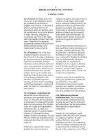
Hardness: The textbook definition
of hardness is the tendency for a mater-
ial to resist deformation. Hardness is
often measured using either the Brinell
or Rockwell scale. The method used to
measure hardness involves embedding a
specific size and shaped indentor into
the surface of the test material, using a
predetermined load or weight. The dis-
tance the indentor penetrates the mater-
ial surface will correspond to a specific
Brinell or Rockwell hardness reading.
The greater the indentor surface pene-
tration, the lower the ultimate Brinell or
Rockwell number, and thus the lower
the corresponding hardness level.
Therefore, high Brinell or Rockwell
numbers or readings represent a mini-
mal amount of indentor penetration into
the workpiece and thus, by definition,
are an indication of an extremely hard
part. Figure 3.1 shows how hardness is
measured.
The Brinell hardness test involves
embedding a steel ball of a specific
diameter, using a kilogram load, in the
surface of a test piece. The Brinell
Hardness Number (BHN) is determined
by dividing the kilogram load by the
area (in square millimeters) of the circle
created at the rim of the dimple or
impression left in the workpiece sur-
face. This standardized approach pro-
vides a consistent method to make com-
www.toolingandproduction.com
Chapter 3/Tooling & Production
3
parative tests between a variety of
workpiece materials or a single material
which has undergone various hardening
processes.
The Rockwell test can be performed
with various indentor sizes and loads.
Several different scales exist for the
Rockwell method or hardness testing.
The three most popular are outlined
below in terms of the actual application
the test is designed to address:
Rockwell T
esting
Scale Application
A For tungsten carbide and
other extremely hard
materials & thin, hard
sheets.
B For medium hardness
low and medium carbon
steels in the annealed
condition.
C For materials > than
Rockwell ‘B’ 100.
In terms of general machining prac-
tice, low material hardness enhances
productivity, since cutting speed is often
selected based on material hardness
(the lower the hardness, the higher the
speed). Tool life is adversely affected by
an increase in workpiece hardness,
since the cutting loads and tempera-
tures rise for a specific cutting speed
with part hardness, thereby reducing
tool life. In drilling and turning, the
added cutting temperature is detrimen-
tal to tool life, since it produces excess
heat causing accelerated edge wear. In
milling, increased material hardness
produces higher impact loads as inserts
enter the cut, which often leads to a pre-
mature breakdown of the cutting edge.
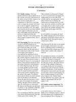
Yield Strength: Tensile test work is
used as a means of comparison of metal
material conditions. These tests can
establish the yield strength, tensile
strength and many other conditions of a
material based on its heat treatment. In
addition, these tests are used to compare
different workpiece materials. The ten-
sile test involves taking a cylindrical rod
or shaft and pulling it from opposite
ends with a progressively larger force in
a hydraulic machine. Prior to the start
of the test, two marks either two or eight
inches apart are made on the rod or
shaft. As the rod is systematically sub-
jected to increased loads, the marks
begin to move farther apart. A material
is in the so-called ‘elastic zone’ when
the load can be removed from the rod
and the marks return to their initial dis-
tance apart of either two or eight inches.
If the test is allowed to progress, a point
is reached where, when the load is
removed the marks will not return to
their initial distance apart. At this point,
permanent set or deformation of the test
specimen has taken place. Figure 3.2
shows how yield strength is measured.
Yield strength is measured just prior
to the point before permanent deforma-
tion takes place. Yield strength is stated
in pounds per square inch (PSI) and is
determined by dividing the load just
prior to permanent deformation by the
cross sectional area of the test speci-
men. This material property has been
referred to as a condition, since it can be
altered during heat treatment. Increased
part hardness produces an increase in
yield strength and therefore, as a part
becomes harder, it takes a larger force to
produce permanent deformation of the
part. Yield strength should not be con-
fused with fracture strength, cracking or
the actual breaking of the material into
pieces, since these properties are quite
different and unrelated to the current
subject.
By definition, a material with high
yield strength (force required per unit of
area to create permanent deformation)
requires a high level of force to initiate
chip formation in a machining opera-
tion. This implies that as a material’s
yield strength increases, stronger insert
shapes as well as less positive cutting
geometries are necessary to combat the
additional load encountered in the cut-
ting zone. Material hardness and yield
strength increase simultaneously during
heat treatment. Therefore, materials
with relatively high yield strengths will
be more difficult to machine and will
reduce tool life when compared to mate-
Chap. 3: Machinability of Metals
Load
500 kg
Large indentation
Small indentation
Soft part
Load
500 kg
Hard partt
Figure 3.1 Hardness is measured by depth of indentations made.
Chap. 3: Machinability of Metals
4
Tooling & Production/Chapter 3
www.toolingandproduction.com
rials with more moderate strengths.
Tensile Strength: The tensile
strength of a material increases along
with yield strength as it is heat treated to
greater hardness levels. This material
condition is also established using a ten-
sile test. Tensile strength (or ultimate
strength) is defined as the maximum
load that results during the tensile test,
divided by the cross-sectional area of
the test specimen. Therefore, tensile
strength, like yield strength, is
expressed in PSI. This value is referred
to as a material condition rather than a
property, since its level just like yield
strength and hardness, can be altered by
heat treatment. Therefore, based on the
material selected, distinct tensile and
yield strength levels exist for each hard-
ness reading.
Just as increased yield strength
implied higher cutting forces during
machining operations, the same could
be said for increased tensile strength.
Again, as the workpiece tensile strength
is elevated, stronger cutting edge
geometries are required for productive
machining and acceptable tool life.
3.3 Physical Properties of
Work Materials
Physical properties will include those
characteristics included in the individ-
ual material groups, such as the modu-
lus of elasticity, thermal conductivity,
thermal expansion and work hardening.
Modulus of Elasticity: The modulus
of elasticity can be determined during a
tensile test in the same manner as the
previously mentioned conditions.
However, unlike hardness, yield or ten-
sile strength, the modulus of elasticity is
a fixed material property and , therefore,
is unaffected by heat treatment. This
particular property is an indicator of the
rate at which a material will deflect
when subjected to an external force.
This property is stated in PSI and typi-
cal values are several million PSI for
metals. A 2” x 4” x 8 ft. wood beam
supported on either end, with a 200
pound weight hanging in the middle,
will sag 17 times more than a beam of
the same dimensions made out of steel
and subjected to the same load. The dif-
ference is not because steel is harder or
stronger, but because steel has a modu-
lus of elasticity which is 17 times
greater than wood.
General manufacturing practice dic-
tates that productive machining of a
workpiece material with a relatively
moderate modulus of elasticity normal-
ly requires positive or highly positive
raked cutting geometries. Positive cut-
ting geometries produce lower cutting
forces and, therefore chip formation is
enhanced on elastic material using
these types of tools. Sharp positive cut-
ting edges tend to bite and promote
shearing of a material, while blunt neg-
ative geometries have a tendency to cre-
ate large cutting forces which impede
chip formation by severely pushing or
deflecting the part as the tool enters the
cut.
Thermal Conductivity: Materials
are frequently labeled as being either
heat conductors or insulators.
Conductors tend to transfer heat from a
hot or cold object at a high rate, while
insulators impede the flow of heat.
Thermal conductivity is a measure of
how efficiently a material transfers heat.
Therefore, a material which has a rela-
tively high thermal conductivity would
be considered a conductor, while one
with a relatively low level would be
regarded as an insulator.
Metals which exhibit low thermal
conductivities will not dissipate heat
freely and therefore, during the machin-
ing of these materials, the cutting tool
and workpiece become extremely hot.
This excess heat accelerates wear at the
cutting edge and reduces tool life. The
proper application of sufficient amounts
of coolant directly in the cutting zone
(between the cutting edge and work-
piece) is essential to improving tool life
in metals with low thermal conductivi-
ties.
Thermal Expansion: Many materi-
als, especially metals, tend to increase
in dimensional size as their temperature
rises. This physical property is referred
to as thermal expansion. The rate at
which metals expand varies, depending
on the type or alloy of material under
consideration. The rate at which metal
expands can be determined using the
material’s expansion coefficient. The
greater the value of this coefficient, the
more a material will expand when sub-
jected to a temperature rise or contract
when subjected to a temperature reduc-
tion. For example, a 100 inch bar of
steel which encounters a 100 degree
Fahrenheit rise in temperature would
measure 100.065 inches. A bar of alu-
minum exposed to the same set of test
conditions would measure 100.125
inches. In this case, the change in the
aluminum bar length was nearly twice
that of the steel bar. This is a clear indi-
cation of the significant difference in
thermal expansion coefficients between
these materials.
In terms of general machining prac-
tice, those materials with large thermal
expansion coefficients will make hold-
ing close finish tolerances extremely
difficult, since a small rise in workpiece
temperature will result in dimensional
change. The machining of these types
of materials requires adequate coolant
supplies for thermal and dimensional
stability. In addition, the use of positive
cutting geometries on these materials
will also reduce machining tempera-
tures.
Work Hardening: Many metals
exhibit a physical characteristic which
produces dramatic increases in hard-
ness due to cold work. Cold work
involves changing the shape of a metal
object by bending, shaping, rolling or
forming. As the metal is shaped, inter-
nal stresses develop which act to harden
the part. The rate and magnitude of this
internal hardening varies widely from
one material to another. Heat also plays
an important role in the work hardening
of a material. When materials which
exhibit work hardening tendencies are
subjected to increased temperature, it
acts like a catalyst to produce higher
hardness levels in the workpiece.
The machining of workpiece materi-
Test Specimen
2.000”
Force = 0 lb
s
Force = 0 lbs
Figure 3.2 Yield strength is measured by pulling a test specimen as shown.
Chap. 3: Machinability of Metals
www.toolingandproduction.com
Chapter 3/Tooling & Production
5
als with work hardening properties
should be undertaken with a generous
amount of coolant. In addition, cutting
speeds should correlate specifically to
the material machined and should not
be recklessly altered to meet a produc-
tion rate. The excess heat created by
unusually high cutting speeds could be
extremely detrimental to the machining
process by promoting work hardening
of the workpiece. Low chip thicknesses
should be avoided on these materials,
since this type of inefficient machining
practice creates heat due to friction,
which produces the same type of effect
mentioned earlier. Positive low force
cutting geometries at moderate speeds
and feeds are normally very effective on
these materials.
3.4 Metal Machining
The term ‘machinability’ is a relative
measure of how easily a material can be
machined when compared to 160
Brinell AISI B1112 free machining low
carbon steel. The American Iron and
Steel Institute (AISI) ran turning tests of
this material at 180 surface feet and
compared their results for B1112
against several other materials. If
B1112 represents a 100% rating, then
materials with a rating less than this
level would be decidedly more difficult
to machine, while those that exceed
100% would be easier to machine.
The machinability rating of a metal
takes the normal cutting speed, surface
finish and tool life attained into consid-
eration. These factors are weighted and
combined to arrive at a final machin-
ability rating. The following chart
shows a variety of materials and their
specific machinability ratings:
3.4.1 Cast Iron
All metals which contain iron (Fe) are
known as ferrous materials. The word
‘ferrous’ is by definition, ‘relating to or
containing iron’. Ferrous materials
include cast iron, pig iron, wrought iron,
and low carbon and alloy steels. The
extensive use of cast iron and steel
workpiece materials, can be attributed
to the fact that iron is one of the most
frequently occurring elements in nature.
When iron ore and carbon are metal-
lurgically mixed, a wide variety of
workpiece materials result with a fairly
unique set of physical properties.
Carbon contents are altered in cast irons
and steels to provide changes in hard-
ness, yield and tensile strengths. The
physical properties of cast irons and
steels can be modified by changing the
amount of the iron-carbon mixtures in
these materials as well as their manu-
facturing process.
Pig iron is created after iron ore is
mixed with carbon in a series of fur-
naces. This material can be changed
further into cast iron, steel or wrought
iron depending on the selected manu-
facturing process.
Cast iron is an iron carbon mixture
which is generally used to pour sand
castings, as opposed to making billets or
bar stock. It has excellent flow proper-
ties and therefore, when it is heated to
extreme temperatures, is an ideal mate-
rial for complex cast shapes and intri-
cate molds. This material is often used
for automotive engine blocks, cylinder
heads, valve bodies, manifolds, heavy
equipment oil pans and machine bases.
Gray Cast Iron: Gray cast iron is an
extremely versatile, very machinable
relatively low strength cast iron used for
pipe, automotive engine blocks, farm
implements and fittings. This material
receives its dark gray color from the
excess carbon in the form of graphite
flakes which give it its name.
Gray cast iron workpieces have rela-
tively low hardness and strength levels.
However, double negative or negative
(axial) positive (radial) rake angle
geometries are used to machine these
materials because of their tendency to
produce short discontinuous chips.
When this type of chip is produced dur-
ing the machining of these workpieces,
the entire cutting force is concentrated
on a very narrow area of the cutting
edge and therefore, double positive rake
tools normally chip prematurely on
these types of materials due to their
lower edge strength.
White Cast Iron: White cast iron
occurs when all of the carbon in the
casting is combined with iron to form
cementite. This is an extremely hard
substance which results from the rapid
cooling of the casting after it is poured.
Since the carbon in this material is
transformed into cementite, the result-
ing color of the material when chipped
or fractured is a silvery white. Thus the
name white cast iron. However, white
cast iron has almost no ductility, and
therefore when it is subjected to any
type of bending or twisting loads, it
fractures. The hard brittle white cast
iron surface is desirable in those
instances where a material with extreme
abrasion resistance is required.
Applications of this material would
include plate rolls in a mill or rock
crushers.
Due to the extreme hardness of white
cast iron, it is very difficult to machine.
Double negative insert geometries are
almost exclusively required for these
materials, since their normal hardness
is 450 - 600 Brinell. As stated earlier
with gray iron, this class of cast materi-
al subjects the cutting edge to extremely
concentrated loads, thus requiring
added edge strength.
Malleable Cast Iron: When white
cast iron castings are annealed (softened
by heating to a controlled temperature
for a specific length of time), malleable
iron castings are formed. Malleable
iron castings result when hard, brittle
cementite in white iron castings is trans-
formed into tempered carbon or
graphite in the form of rounded nodules
or aggregate. The resulting material is a
strong, ductile, tough and very machin-
able product which is used on a broad
scope of applications.
Malleable cast irons are relatively
easy to machine when compared to
white iron castings. However, double
negative or negative (axial)
positive(radial) rake angle geometries
are also used to machine these materi-
als as with gray iron, because of their
tendency to produce short discontinu-
ous chips.
Nodular Cast Iron: Nodular or
‘ductile’ iron is used to manufacture a
MaterialHardness
Machinability
Rating
6061-T
Aluminum —
190%
7075-T
Aluminum —
120%
B1112
Steel 160 BHN
100%
416 Stainless
Steel 200 BHN
90%
1120 Steel160 BHN
80%
1020 Steel148 BHN