Tài liệu Cutting Tools P5 pdf
Bạn đang xem bản rút gọn của tài liệu. Xem và tải ngay bản đầy đủ của tài liệu tại đây (838.73 KB, 8 trang )
2
Tooling & Production/Chapter 5
www.toolingandproduction.com
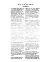
5.1 Introduction
The basic engine lathe, which is one of the most widely used machine tools, is very ver-
satile when used by a skilled machinist. However, it is not particularly efficient when
many identical parts must be machined as rapidly as possible. As far back as 1850 there
were efforts to develop variations of an engine lathe that could be operated by a relatively
unskilled person for mass producing machined parts. The cutting tools were preset, or
“set up” by a skilled machinist, and usually several cutting tools were in operation at the
same time, reducing the time spent in machining each part. This is still the basic concept
on which mass- production type lathes are based.
The turret lathe and automatic screw machine in their various forms have been devel-
oped and improved with the objectives of producing machined parts more rapidly and
accurately at lower cost. On most machines of this type, the power available at the spin-
dle has been greatly increased to take advantage of better cutting tool material.
Mechanical power, in electrical, hydraulic, or pneumatic form, has replaced human mus-
cle power for such functions as feeding tools, operating chucks or collets, and feeding bar
stock in the machine.
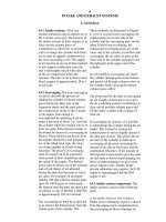
5.2 Lathes and Lathe Components
Of the many standard and special types of turning machines that have been built, the most
important, most versatile, and most widely recognized is the engine lathe. The standard
engine lathe is not a high production machine, but it can be readily tooled up for many
one-piece or short-run jobs. It is also possible to modify the basic machine for many high-
er production applications. The modern engine lathe provides a wide range of speeds and
feeds which allow optimum settings for almost any operation. There have been advances
in headstock design to provide greater strength and rigidity. This allows the use of high-
horsepower motors so that heavy cuts with carbide tools are practical. To utilize this high
power without losing accuracy, new lathes incorporate heavier beds, wider hardened
ways, and deeper-sectioned carriages.
A schematic illustration of the components of an engine lathe is shown and described
in Figure 5.1.
Headstock: The headstock is the powered end and is always at the operator’s left.
This contains the speed changing gears and the revolving, driving spindle, to which any
one of several types of work holders is attached. The center of the spindle is hollow so
that long bars may be put through it for machining.
Tailstock: The tailstock is non-rotating but on hardened ways, it can be moved, to the
left or right, to adjust to the length of the work. It can also be offset for cutting small-
angle tapers.
Carriage: The carriage can be moved left or right either by handwheel or power feed.
This provides the motion along the Z-axis. During this travel turning cuts are made.
Apron: The apron attached to the front of the carriage, holds most of the control
levers. These include the levers which engage and reverse the feed lengthwise (Z-axis)
Chapter 5
Turning Methods
& Machines
Upcoming Chapters
Metal Removal
Cutting-Tool Materials
Metal Removal Methods
Machinability of Metals
Single Point Machining
Turning Tools and Operations
Turning Methods and Machines
Grooving and Threading
Shaping and Planing
Hole Making Processes
Drills and Drilling Operations
Drilling Methods and Machines
Boring Operations and Machines
Reaming and Tapping
Multi Point Machining
Milling Cutters and Operations
Milling Methods and Machines
Broaches and Broaching
Saws and Sawing
Finishing Processes
Grinding Wheels and Operations
Grinding Methods and Machines
Lapping and Honing
George Schneider, Jr. CMfgE
Professor Emeritus
Engineering Technology
Lawrence Technological University
Former Chairman
Detroit Chapter ONE
Society of Manufacturing Engineers
Former President
International Excutive Board
Society of Carbide & Tool Engineers
Lawrence Tech.Univ.:
Prentice Hall:
or crosswise (X-axis) and the lever
which engages the threading gears.
Cross Slide: The cross slide is
mounted on the carriage and can be
moved in and out (X-axis) perpendicu-
lar to the carriage motion. This is the
part that moves when facing cuts are
made with power feed, or at any time a
cut must be made ‘square’ with the Z-
axis. This, or the compound, is also
used to set the depth of cut when turn-
www.toolingandproduction.com
Chapter 5/Tooling & Production
3
ing. The cross slide can be moved by its
handwheel or by power feed.
Compound Rest: The compound
rest, or compound for short, is mounted
on the carriage. It can be moved in and
out by its handwheel for facing or for
setting the depth of cut. It can also be
rotated 360 degrees and fed by its hand-
wheel at any angle. The compound
does not have any power feed but it
always moves longitudinally with the
cross slide and the car-
riage.
Tool Post: The tool
post is mounted on the
compound rest. This can
be any of several varieties
but in its simplest form is
merely a slotted cylinder which can be
moved left or right in the T-slot in the
compound and clamped in place. It can
also be rotated so as to present the cut-
ter to the work at whatever angle is best
for the job.
Bed: The bed of the lathe is its
‘backbone’. It must be rigid enough to
resist deflection in any direction under
load. The bed is made of cast iron or a
steel weldment, in a box or I-beam
shape, and is supported on legs, a cabi-
net, or a bench.
Ways: The ways of the lathe are the
flat or V-shaped surfaces on which the
carriage and the tailstock are moved left
and right. Each has its separate pair of
ways, often one flat surface, for stabili-
ty, and one V-way for guidance in a per-
fectly straight line. These ways are
hardened and scraped or ground to close
tolerances. The basic accuracy of
movement of the carriage depends on
the ways. A typical Toolroom Engine
Lathe is shown in Figure 5.2.
Size: The size of a lathe is specified
by two or three dimensions:
• The largest diameter workpiece which
will clear the bed of the lathe. The cen-
ter is the headstock spindle center.
• The largest diameter workpiece which
will clear the cross slide is sometimes
also specified.
• The longest workpiece which can be
held on centers between the headstock
and the tailstock.
A larger, more sophisticated lathe is
shown in Figure 5.3.
A large 40” lathe with a steady rest is
shown in Figure 5.4.
5.3 Turret Lathe
The standard engine lathe is versatile,
Spindle
speed
selector
Headstock
Feed change
gear box
Compound rest
Spindle
Ways
Tool post
Cross slide
Carriage
Center
Tailstock quill
Tailstock
Apron
Bed
Lead screw
Feed rod
FIGURE 5.1: Schematic illustration of the components of a standard engine lathe.
FIGURE 5.2: A typical toolroom engine lathe with face
plate, square turrent, follower, and steady rest. (Courtesy
Summit Machine Tool Manufacturing Corp.)
FIGURE 5.3: A more sophisticated 18-inch variable speed engine lathe
permits optimal cutting speed selection. (Courtesy Clausing Industries,
Inc.)
Chap. 5: Turning Methods & Machines
Chap. 5: Turning Methods & Machines
4
Tooling & Production/Chapter 5
www.toolingandproduction.com
but it is not a high production machine.
When production requirements are
high, more automated turning machines
must be used.
The turret lathe represents the first
step from the engine lathe toward the
high production turning machines. The
turret lathe is similar to the engine lathe
except that tool-holding turrets replace
the tailstock and the tool post compound
assembly. These machines possess spe-
cial features that adapt them to produc-
tion. The ‘skill of the worker’ is built
into these machines, making it possible
for inexperienced operators to repro-
duce identical parts. In contrast, the
engine lathe requires a skilled operator
and requires more time to produce parts
that are dimensionally the same.
The principal characteristic of turret
lathes is that the tools for consecutive
operations are set up for use in the prop-
er sequence. Although skill is required
to set and adjust the tools prop-
erly, once they are correct, less
skill is required to operate the
turret lathe. Many parts can be
produced before adjustments are
necessary. These machines are
normally used for small to medi-
um sized production runs where
the engine lathe is too slow but
the additional production rate
desired does not warrant a spe-
cial machine.
A schematic illustration of the
components of a turret lathe is
shown in Figure 5.5.
Square and Hex Turrets: A
square turret is mounted on the
top of the cross slide and is capa-
ble of holding four tools. If sev-
eral different tools are required,
they are set up in sequence and
can be quickly indexed and
locked in correct working posi-
tion. So that cuts can be dupli-
cated, the slide is provided with
positive stops or feed trips. Likewise,
the longitudinal position of the entire
assembly may be controlled by positive
stops on the left side of the apron. Cuts
may be taken with square turret tools
and with tools mounted on the hexagon
turret simultaneously.
An outstanding feature is the turret in
place of the tailstock. This turret
mounted on either the sliding ram or the
saddle, or on the back of the structure,
carries anywhere from 4 to 18 tool sta-
tions. The tools are preset for the vari-
ous operations. The tools are mounted
in proper sequence on the various faces
of the turret so that as the turret indexes
between machining operations, the
proper tools are engaged into position.
For each tool there is a stop screw or
electric/electronic transducer, which
controls the distance the tool will feed
and cut. When this distance is reached,
an automatic trip lever stops further
movement of the tool by disengag-
ing the drive clutch.
Like the engine lathe, the mod-
ern turret lathe provides fast spin-
dle speeds, wide speed and feed
ranges, high power, and great rigid-
ity. The machine is operated in the
high end of its speed range more
than the engine lathe is, partly
because the tools placed in the tur-
ret often work on small diameters
on the workpiece, but also because
the operator is more production
conscious.
5.3.1 Horizontal Turret Lathes:
Horizontal turret lathes are made in two
general designs and are known as the
ram and saddle types. The ram-type tur-
ret lathe shown in Figure 5.6a has the
turret mounted on a slide or ram which
moves back and forth on a saddle
clamped to the lathe bed. The saddle-
type turret lathe shown in Figure 5.6b
has the turret mounted directly on a sad-
dle which moves back and forth with
the turret.
5.3.2 Vertical Turret Lathes: A ver-
tical turret lathe resembles a vertical
boring mill, but it has the characteristic
turret arrangement for holding the tools.
It consists of a rotating chuck or table in
the horizontal position with the turret
mounted above on a cross rail. In addi-
tion, there is at least one side head pro-
vided with a square turret for holding
tools. All tools mounted on the turret or
Spindle
speed selector
Forward and
reverse
Stop rod
Feed
shaft
Longitudinal
feed lever
Carriage
handwheel
Cross-slide
handwheel
Cross-
feed
lever
Feed selectors
Turnstile
Square
turret
Hexagon
turret
Ram
Turret
stops
FIGURE 5.4: 40 inch lathe with steady rest is used to machine large cylindrical parts.(Courtesy
Summit Machine Tool Manufacturing Corporation)
FIGURE 5.5: Schematic illustration of the components of a turret lathe.
Chap. 5: Turning Methods & Machines
www.toolingandproduction.com
Chapter 5/Tooling & Production
5
side head have their respective
stops set so that the length of cuts
can be the same in successive
machining cycles. It is, in effect,
the same as a turret lathe standing
on the headstock end, and it has all
the features necessary for the pro-
duction of duplicate parts. This
machine was developed to facilitate
mounting, holding, and machining
of large diameter heavy parts. Only
chucking work is done on this kind
of machine.
A vertical turret lathe, shown in
Figure 5.7, is provided with two cutter
heads: the swiveling main turret head
and the side head. The turret and side
heads function in the same manner as
the hexagonal and square turrets on a
horizontal lathe. To provide for angle
cuts both the ram and turret heads may
be swiveled 30 degrees right or left of
center.
The machine can be provided with a
control that permits automatic operation
of each head including rate and direc-
tion of feed, change in spindle feed,
indexing of turret, starting, and stop-
ping. Once a cycle of operations is pre-
set and tools are properly adjusted, the
operator need only load, unload, and
start the machine. Production rate is
increased over those manually operated
machines, because they operate almost
continuously and make changes from
one operation to another without hesita-
tion or fatigue. By reducing the han-
dling time, and making the cycle auto-
matic, an operator can attend more than
one machine.
The turret lathe normally has a jawed
chuck to hold the workpiece; however, a
collet may be more suitable when pro-
ducing parts from bar stock. A turning
machine equipped with a collet and a
turret is called a screw machine, but it is
actually a special turret lathe. The spe-
cial features of screw machines are
aimed primarily at reducing idle time on
the parts being machined, thereby
increasing productivity.
In Figure 5.8 a vertical turning center
is shown machining a heavy part.
5.3.3 Advantages of Turret Lathes:
The difference between the engine and
turret lathes is that the turret lathe is
adapted to quantity production work,
whereas the engine lathe is used primar-
ily for miscellaneous jobbing, toolroom,
or single-operation work. The features
of a turret lathe that make it a quantity
production machine are:
• Tools may be set up in the turret in the
proper sequence for the operation.
• Each station is provided with a feed
stop or feed trip so that each cut of a
tool is the same as its previous cut.
• Multiple cuts can be taken from the
same station at the same time, such as
two or more turning and/or boring cuts.
• Combined cuts can be made; tools on
the cross slide can be used at the same
time that tools on the turret are cutting.
• Rigidity in holding work and tools is
FIGURE 5.6a: Ram-type horizontal turret lathe has the turret mounted on a slide or
ram. (Courtesy: National Acme Co., Div. DeVlieg-Bullard Inc.)
FIGURE 5.6b: Saddle-type turret lathe has the turret mounted directly on the saddle.
(Courtesy National Acme Co., Div. DeVlieg-Bullard Inc.)
FIGURE 5.7: Vertical turning lathes
are used for machining large-diame-
ter and heavy parts.
Ram
Turret
Workpiece
Cross rail
Column
Base
Cross slide
Chap. 5: Turning Methods & Machines
6
Tooling & Production/Chapter 5
www.toolingandproduction.com
built into the machine to permit multiple
and combined cuts.
• Turret lathes can also have attach-
ments for taper turning, thread chasing
and duplicating, and can be tape con-
trolled.
5.4 Automated Equipment
There are turning machines which allow
automatic chucking, indexing, feeding,
spindle speed changes, and other work
that has to be done by the operator on
the engine lathe. These automatic lath-
es represent a refinement of the turret
lathe, and they are particularly suitable
for long run, mass production applica-
tions.
Automatic lathes may be made up as
single-spindle or multiple-spindle
machines. Generally, single-spindle
machines provide for turning the work-
piece, which is held in a collet or
chucked on the headstock. Multiple-
spindle automatic lathes usually provide
means for indexing the workpiece to
tools mounted on the various spindles.
These tools might include drills, coun-
tersinks, boring bars, and other rotating
cutters. Both single- and multiple-spin-
dle automatics may be made up with
vertical as well as horizontal spindle
alignment.
As far as the machining processes on
an automatic lathe are concerned, the
fundamental considerations are the high
speeds desired for good productivity,
the economics of the cutting process,
and the balancing of speeds on various
phases of the operation to obtain the
desired rate of wear on each cutting
tool.
5.4.1 Single-Spindle Automatic
Lathes
The majority of single-spindle automat-
ic lathes are designed to machine work-
pieces that are located between two cen-
ters. Some, however, hold the work-
piece in a chuck, collet, or specially
designed fixture. Most have horizontal
spindles. A conventional single-spindle
automatic lathe has six major compo-
nents: base, bed, and ways; headstock;
work spindle; front tool slide; rear tool
slide.
The feed rates of the tool slides are
controlled by cams, hydraulics, or lead
screws. Spindle speeds are changed to
suit workpiece diameter/material
requirements by means of change gears
in the headstock.
A single-spindle
automatic lathe is
shown in Figure 5.9.
Tooling: Any of the
several available work-
piece holders that are
suitable for the particu-
lar application may be
used, including chucks,
faceplate drives, collets,
and specially designed
fixtures. Chucks,
where used, should be
power operated to avoid
the time lost to manual-
ly actuate chucks.
Toolholders are nor-
mally designed with
slots to locate, and
clamps to hold individ-
ual cutting tools in their
required locations. The
assembled toolholders are, in turn,
keyed and clamped in a specific loca-
tion on the front and rear tool slides.
It is good practice to provide spare
toolholders wherein a set of sharpened
tools can be preset and clamped, ready
to exchange for a set of dull tools.
Setup time can also be saved by having
spare toolholders preset with the tools
required for the next part to be run.
DeVlieg tooling for a single- or mul-
tiple-spindle automatic lathe is shown
in Figure 5.10.
Applications: Axle and transmission
shafts, gear blanks, pump drives, and pin-
ions are all particularly well suited for
machining on single-spindle automatic
lathes. In fact, almost any machinable
metal part falling within its size capacity
that can be chucked, fixtured, or run
between centers is a potential candidate
for this machine. Single-spindle auto-
matic lathes perform turning, facing,
chamfering, grooving, and forming oper-
ations, and are usually used for parts with
moderate production rates.
FIGURE 5.9: Single-spindle automatic lathe (Courtesy: National Acme Co., Div.
DeVlieg-Bullard Inc.)
FIGURE 5.8: A vertical turning center
machining a heavy part. (Courtesy Giddings & Lewis, LLC)