Tài liệu Micromaster pdf
Bạn đang xem bản rút gọn của tài liệu. Xem và tải ngay bản đầy đủ của tài liệu tại đây (4.22 MB, 125 trang )
U1_U4_Ruecken_DA_51_2_en_05-06.FH10 Tue Oct 04 11:42:52 2005 Seite 3
Probedruck
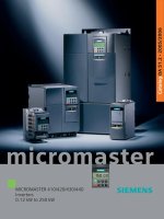
MICROMASTER 410/420/430/440
Inverters
0.12 kW to 250 kW
Catalog DA 51.2
•
2005/2006
micromaster
Related catalogs
SINAMICS G110 D 11.1
Converter Chassis Units
0.12 kW (0.16 HP) to
3 kW (4 HP)
Order No.:
German: E86060-K5511-A111-A2
English: E86060-K5511-A111-A2-7600
SINAMICS G130 D 11
Converter Chassis Units
SINAMICS G150
Converter Cabinet Units
Order No.:
German: E86060-K5511-A101-A3
English: E86060-K5511-A101-A3-7600
MICROMASTER/COMBIMASTER DA 51.3
MICROMASTER 411 Inverters
Distributed Drive Solutions
COMBIMASTER 411
Order No.:
German: E86060-K5251-A131-A2
English: E86060-K5251-A131-A2-7600
Industrial Communication IK PI
for Automation and Drives
Part 6: Distributed I/Os ET 200
Frequency Converter ET 200S FC
Order No.:
E86060-K6710-A101-B4-7600
Low-Voltage Motors M 11
Order No.:
German: E86060-K1711-A101-A3
English: E86060-K1711-A101-A3-7600
Geared Motors M 15
Helical, Flat, Bevel-helical,
Helical-worm
and Worm Geared Motors
Order No.:
E86060-K1715-A101-A5
(available in German only)
Catalog CA 01 CA 01
The Offline Mall of Automation and Drives
Order No.:
CD-ROM: E86060-D4001-A100-C4 (Germ.)
CD-ROM: E86060-D4001-A110-C4-7600 (Engl.)
DVD: E86060-D4001-A500-C4 (Germ.)
A&D Mall
Internet:
/>Catalog CA 01 – SD configurator selection aid
The SD configurator selection aid will be available in combination
with the CA 01 electronic catalog.
On CD 2 of the selection and configuration aids you will find the SD
configurator for low-voltage motors, MICROMASTER 4 inverters,
inverter chassis units SINAMICS G110 and frequency converters for
distributed I/Os SIMATIC ET 200S FC including:
• Dimension drawing generator for motors
• Data sheet generator for motors
• Starting calculation
• 3D models in .stp format
• Extensive documentation
Hardware and software requirements
• PC with Pentium II or comparable processor
• Operating systems
– Windows 98/ME
– Windows 2000
– Windows XP
– Windows NT
(Service Pack 5 upwards)
• Minimum of 128 RAM
• 1024 x 768 graphics with more than 256 colors / small fonts
•CD-ROM drive
• Windows-compatible sound card
• Windows-compatible mouse
Installation
You can install this catalog directly from the CD-ROM as a complete
or partial version on your hard disk or in the network.
Hotline:
For technical advice and hotline support concerning our CA 01
catalog:
Tel.: +49 (0) 180 50 50 22 2
E-Mail:
Trademarks
All product designations may be trademarks or product
names of Siemens AG or supplier companies whose
use by third parties for their own purposes could
violate the rights of the owners.
s
Supersedes:
Catalog DA 51.2 · 2003/2004
The products in this catalog are also included
in the CD-ROM catalog CA 01.
Order No.:
E86060-D4001-A110-C4-7600 (CD-ROM)
Contact your local Siemens representative
for further information
© Siemens AG 2005
MICROMASTER
410/420/430/440
Inverters
0.12 kW to 250 kW
Catalog DA 51.2
2005/2006
The products and sys-
tems described in this
catalog are manufac-
tured/distributed under
application of a certified
quality management
system in accordance
with DIN EN ISO 9001
(Certified Registration
No. 000357 QM) and
DIN EN ISO 14001
(Certified Registration
No. 081342 UM and
EMS 57390). The cer-
tificate is recognized by
all IQNet countries.
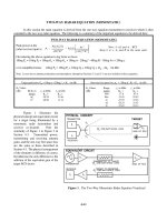
Overview
Welcome to
Automation and Drives
Selection guide
MICROMASTER inverters
Overview of options
0
MICROMASTER 410
“The low-priced”
0.12 kW to 0.75 kW
1
MICROMASTER 420
“The universal”
0.12 kW to 11 kW
2
MICROMASTER 430
“The specialist for
pumps and fans”
7.5 kW to 250 kW
3
MICROMASTER 440
“The all-purpose”
0.12 kW to 250 kW
4
Appendix
Certificates/Standards
Demonstration case/
Training
Overview of motors and
inverters
Siemens contacts
Online services
Service & Support
Conditions of sale and
delivery
Export regulations
A
Siemens DA 51.2 · 2005/2006 Siemens DA 51.2 · 2005/2006
Welcome to
Automation and Drives
We would like to welcome you to Automation and Drives
and our comprehensive range of products, systems,
solutions and services for production and
process automation and building technology
worldwide.
With Totally Integrated Automation and Totally
Integrated Power, we deliver solution platforms based
on standards that offer you a considerable savings
potential.
Discover the world of our technology now. If you need
more detailed information, please contact one of your
regional Siemens partners.
They will be glad to assist you.
0/2 0/3
Sprachumschaltung über
Spezial - Bedingter Text -
Ein-/Ausblenden
Siemens DA 51.2 · 2005/2006 Siemens DA 51.2 · 2005/2006
I
ndustrial
E
thernet
PROCESS FIELD
GAMMA instabus
ERP
Enterprise
Resource
Planning
MES
Manufacturing
Execution
Systems
Ethernet
Ethernet
Plant
Information
Management
Detailed
Production
Scheduling
SIMATIC IT Framework
Production Modeler
Material
Management
Equipment
Management
Production
Order
Management
Production
Operations
Recording
Product Specification
Management System
Laboratory Information
Management System
SIMATIC PCS 7
Process Control
System
SIMATIC
Controller/
Automation
System
SIMATIC NET
Industrial
Communication
SIMATIC HMI
Human Machine
Interface
Drive Systems/
SINAMICS
Industrial Wireless
Communication/
MOBIC
ECOFAST IP65
Distributed
Automation System
Micro-Automation
and
Actuator-Sensor
Interface Level
AS-Interface
PROFIBUS
Industrial
Ethernet
Safety Integrated
SENTRON
Circuit-
Breakers
Control
SINAUT Telecontrol
System
SIMATIC
Software
SIMATIC
Machine Vision
PC-based Automation
Sensor
Technology
IQ-Sense
SIMATIC
Distributed
I/O
SIMOTION
Motion Control
System
SINUMERIK
Numeric
Control
SIMOCODE pro
Motor Manage-
ment System
SINAMICSSIMODRIVE
Building
Technology
PROFIBUS PA
HART
SIWAREX
Weighing
Technology
Process
Instrumen-
tation and
Analytics
Totally Integrated Automation –
innovations for more productivity
With the launch of Totally Integrated Automation, we were the
first ones on the market to consistently implement the trend
from equipment to an integrated automation solution, and
have continuously improved the system ever since.
Whether your industry is process- and production-oriented or
a hybrid, Totally Integrated Automation is a unique “common
solution” platform that covers all the sectors.
Totally Integrated Automation is an integrated platform for the
entire production line - from receiving to technical processing
and production areas to shipping. Thanks to the system-
oriented engineering environment, integrated, open commu-
nications as well as intelligent diagnostics options, your plant
now benefits in every phase of the life cycle.
In fact, to this day we are the only company worldwide that can
offer a control system based on an integrated platform for both
the production and process industry.
0/4 0/5
Siemens DA 51.2 · 2005/2006 Siemens DA 51.2 · 2005/2006
Siemens DA 51.2 · 2005/2006 Siemens DA 51.2 · 2005/2006
I
ndustrial
E
thernet
PROCESS FIELD
GAMMA instabus
ERP
Enterprise
Resource
Planning
MES
Manufacturing
Execution
Systems
Ethernet
Ethernet
Plant
Information
Management
Detailed
Production
Scheduling
SIMATIC IT Framework
Production Modeler
Material
Management
Equipment
Management
Production
Order
Management
Production
Operations
Recording
Product Specification
Management System
Laboratory Information
Management System
SIMATIC PCS 7
Process Control
System
SIMATIC
Controller/
Automation
System
SIMATIC NET
Industrial
Communication
SIMATIC HMI
Human Machine
Interface
Drive Systems/
SINAMICS
Industrial Wireless
Communication/
MOBIC
ECOFAST IP65
Distributed
Automation System
Micro-Automation
and
Actuator-Sensor
Interface Level
AS-Interface
PROFIBUS
Industrial
Ethernet
Safety Integrated
SENTRON
Circuit-
Breakers
Control
SINAUT Telecontrol
System
SIMATIC
Software
SIMATIC
Machine Vision
PC-based Automation
Sensor
Technology
IQ-Sense
SIMATIC
Distributed
I/O
SIMOTION
Motion Control
System
SINUMERIK
Numeric
Control
SIMOCODE pro
Motor Manage-
ment System
SINAMICSSIMODRIVE
Building
Technology
PROFIBUS PA
HART
SIWAREX
Weighing
Technology
Process
Instrumen-
tation and
Analytics
Totally Integrated Automation –
innovations for more productivity
With the launch of Totally Integrated Automation, we were the
first ones on the market to consistently implement the trend
from equipment to an integrated automation solution, and
have continuously improved the system ever since.
Whether your industry is process- and production-oriented or
a hybrid, Totally Integrated Automation is a unique “common
solution” platform that covers all the sectors.
Totally Integrated Automation is an integrated platform for the
entire production line - from receiving to technical processing
and production areas to shipping. Thanks to the system-
oriented engineering environment, integrated, open commu-
nications as well as intelligent diagnostics options, your plant
now benefits in every phase of the life cycle.
In fact, to this day we are the only company worldwide that can
offer a control system based on an integrated platform for both
the production and process industry.
0/4 0/5
Siemens DA 51.2 · 2005/2006 Siemens DA 51.2 · 2005/2006
Siemens DA 51.2 · 2005/2006
0/6
MICROMASTER 410/420/430/440
0
Overview
MICROMASTER
®
410/420/430/440
■
Selection guide
Main characteristics
“The low-priced”
for variable speeds with three-phase motors
on single-phase networks, e.g. with pumps,
fans, billboards, barriers, gate drives and
automatic machines
“The universal”
for three-phase networks and optional
fieldbus interfacing, e.g. for conveyor belts,
material transport, pumps, fans and machine tools
Power ranges 0.12 kW to 0.75 kW 0.12 kW to 11 kW
Voltage ranges 1 AC 100 V to 120 V
1 AC 200 V to 240 V
1 AC 200 V to 240 V
3 AC 200 V to 240 V
3 AC 380 V to 480 V
Control methods • V/f characteristic
• Multipoint characteristic
(programmable V/f characteristic)
• FCC (flux current control)
• V/f characteristic
• Multipoint characteristic
(programmable V/f characteristic)
• FCC (flux current control)
Process control – Internal PI controller
Inputs 3 digital inputs
1 analog input
3 digital inputs
1 analog input
Outputs 1 relay output 1 analog output
1 relay output
Interfacing to automation
system
The PLC partner for LOGO! and
SIMATIC S7-200
The ideal partner for your automation tasks,
whether with SIMATIC S7-200,
SIMATIC S7-300/400 (TIA) or SIMOTION
Additional features • Natural ventilation (no fan unit)
• Position of connections as with convention-
al switching elements (e.g. contactors)
• Variant with flat plate heatsink
• BICO technology
• Compound braking for controlled rapid braking
MICROMASTER 410
MICROMASTER 410
MICROMASTER 420
MICROMASTER 420
Section 1
Section 1
Section 2
Section 2
Siemens DA 51.2 · 2005/2006
0/7
MICROMASTER 410/420/430/440
0
Overview
“The specialist for pumps and fans”
with optimized OP (manual/automatic switchover), matched
software functionality and optimized power yield
“The all-purpose”
with advanced vector control (with and without encoder feedback)
for versatile applications in sectors such as conveying systems,
textiles, elevators, hoisting equipment and machine construction
7.5 kW to 250 kW 0.12 kW to 250 kW
3 AC 380 V to 480 V 1 AC 200 V to 240 V
3 AC 200 V to 240 V
3 AC 380 V to 480 V
3 AC 500 V to 600 V
• V/f characteristic
• Multipoint characteristic
(programmable V/f characteristic)
• FCC (flux current control)
• V/f characteristic
• Multipoint characteristic
(programmable V/f characteristic)
• FCC (flux current control)
• Vector control
Internal PID controller Internal PID controller
(autotuning)
6 digital inputs
2 analog inputs
1 PTC/KTY input
6 digital inputs
2 analog inputs
1 PTC/KTY input
2 analog outputs
3 relay outputs
2 analog outputs
3 relay outputs
The ideal partner for your automation tasks, whether with
SIMATIC S7-200, SIMATIC S7-300/400 (TIA) or SIMOTION
The ideal partner for your automation tasks, whether with
SIMATIC S7-200, SIMATIC S7-300/400 (TIA) or SIMOTION
• Low-energy mode
• Load torque monitoring
(detects dry run of pumps)
• Motor staging
• Bypass mode
• BICO technology
• 3 selectable drive data kits
• Integrated brake chopper (up to 75 kW)
• Torque control
• BICO technology
MICROMASTER 430
MICROMASTER 430
MICROMASTER 440
MICROMASTER 440
Section 3
Section 3
Section 4
Section 4
0/8
Siemens DA 51.2 · 2005/2006
MICROMASTER 410/420/430/440
0
■
Options
Operator panels
Modules
Various options are available
for the MICROMASTER
inverters:
■
Filters
■
Chokes
■
Operator panels
■
PROFIBUS module
■
DeviceNet module
■
CANopen module
■
Pulse encoder evaluation
module
■
Gland plates
■
Mounting kits, etc.
Assignment of operator panels and modules to the inverter ranges
Options Order No. MICROMASTER
410 420 430 440
Operator panels
OP 6SE6400-0SP00-0AA0 %
BOP 6SE6400-0BP00-0AA0 % %
BOP-2 6SE6400-0BE00-0AA0 %
AOP 6SE6400-0AP00-0AA1 % %
AAOP 6SE6400-0AP00-0AB0 % %
Modules
PROFIBUS 6SE6400-1PB00-0AA0 % % %
DeviceNet 6SE6400-1DN00-0AA0 % % %
CANopen 6SE6400-1CB00-0AA0 % % %
Pulse encoder evaluation 6SE6400-0EN00-0AA0 % %
% Possible combination
OP/BOP
AOP
BOP-2
AAOP
PROFIBUS
DeviceNet Pulse encoder evaluation
CANopen
Overview
Siemens DA 51.2 · 2005/2006
1/1
1
Inverter
MICROMASTER 410
1/2
Description
1/4
Circuit diagrams
1/6
Technical data
1/7
Selection and ordering data
1/8
Options
1/10
Dimension drawings
1/2
Siemens DA 51.2 · 2005/2006
MICROMASTER 410
1
■
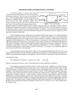
Application
The MICROMASTER 410 in-
verter is suitable for a variety
of variable-speed drive appli-
cations.
It is especially suitable for use
with pumps and fans, as a
drive in various sectors, e.g.
food, textile and packaging in-
dustries as well as for convey-
or systems, factory gate and
garage door drives and as a
universal drive for moving bill-
boards.
It is the ideal low-cost frequen-
cy inverter solution for the low-
end performance range of the
MICROMASTER product fam-
ily.
The inverter is especially char-
acterized by its customer-ori-
ented performance and ease-
of-use.
Versions for connecting to
230 V and 115 V single-phase
networks enable it to be used
all over the world.
■
Design
The MICROMASTER 410 in-
verter has a compact design.
Heatsinks provide natural
cooling for the inverter. A fan
unit is not used.
The position of the connec-
tions has been selected as for
conventional contactors.
The operator panel available
as an option can be easily fit-
ted without requiring any tools.
The design with flat plate heat-
sink offers space-saving and
favorable heat dissipation
since an additional heatsink
can be installed outside the
control cabinet.
■
Main characteristics
■
Simple selection from mini-
mum range of types (only a
few options)
■
Compact design
■
Natural cooling with heat
sinks (no fan unit)
■
Simple connection similar
to conventional switching
elements (e.g. contactors)
■
Versions with internal EMC
filter Class B
■
Fast, simple commission-
ing with input of only a few
parameters (fast commis-
sioning mode)
■
Integrated RS-485 commu-
nications interface
■
Three programmable digi-
tal inputs, non-floating (the
analog input can be used
as a fourth binary input)
■
One analog input
(0 V to 10 V)
■
One programmable relay
output
(30 V DC/5 A resistive load;
250 V AC/2A inductive
load)
■
Low-noise motor operation
resulting from high pulse
frequency
■
Integrated protection for
motor and inverter.
■
Options (overview)
■
Line commutating chokes
■
Adapter for standardized
mounting on DIN rails
■
OP (Operator Panel) for
user-friendly parameteriza-
tion of an inverter
■
Connection kit for PC to in-
verter
■
PC startup program.
■
International standards
■
The MICROMASTER 410
inverter complies with the
requirements of the EU low-
voltage guideline
■
The MICROMASTER 410
inverter has the > mark-
ing
■
u and cu listed (not for ver-
sions with flat heat sinks)
■
c-tick
●
✔
Note:
See Appendix for standards.
Inverter
Frame size AA
Inverter
Frame size AB
Inverter
with flat heat sink
Description
Siemens DA 51.2 · 2005/2006
1/3
MICROMASTER 410
1
■
Mechanical features
■
Performance features
■
Protection features
■
Compact design
■
Heat dissipation through
self-ventilation (convection)
■
Operating temperature
–10 °C to +50 °C
(+14 °F to +122 °F)
■
Easy cable connection,
mains and motor connec-
tions are separated for opti-
mal electromagnetic com-
patibility and clear
connection
■
Detachable, optional oper-
ator panels
■
Screwless control terminals
■
Side mounting possible,
thus also usable with low
cabinet depth.
■
Latest IGBT technology
■
Digital microprocessor
control
■
Linear V/f characteristic,
with programmable voltage
boosting
■
Quadratic V/f characteristic
■
Multipoint characteristic
(programmable V/f charac-
teristic)
■
Flying restart
■
Automatic restart after
mains failure or fault
■
Programmable ramp gener-
ator (0 s to 650 s) with pos-
sible rounding
■
Fast current limit (FCL) for
trip-free operation
■
Fast, repeatable digital in-
put response time
■
Exact setpoint specification
using a high-resolution
10-bit analog input
■
One skip frequency range
■
Removable Y cap for use in
IT systems
■
Serial RS-485 interface with
USS protocol
■
LED for status information
■
Versions with internal EMC
filter Class B
■
Overload current 1.5 x rat-
ed output current (i.e.150 %
overload capability) for
60 s, then 0.85 x rated out-
put current for 240 s, cycle
time 300 s
■
Overvoltage/undervoltage
protection
■
Inverter overtemperature
protection
■
Earth fault protection
■
Short-circuit protection
■
I
2
t motor thermal protection
■
Stall prevention.
Description
1/4
Siemens DA 51.2 · 2005/2006
MICROMASTER 410
1
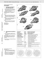
■
General circuit diagram
7
4
5
2 4 V
+
-
D I N 4
V o l t a g e s u p p l y
( e x t e r n a l
o r
i n t e r n a l
s o u r c e )
F o r a n a d d i t i o n a l d i g i t a l i n p u t ( D I N 4 ) e x t e r n a l
c o n n e c t i o n s s h o u l d b e m a d e :
G _ D A 5 1 _ E N _ 0 5 0 3 4 b
1
2
3
4
5
6
7
8
2 4 V
+
-
D I N 1
D I N 2
D I N 3
A I N +
R L 1 - B
R L 1 - C
P +
N -
1 1
1 2
9
R L 1
+ 1 0 V
M
3 ~
A
D
C P U
P E
P E
F S 1
P E
U , V , W
1 0
-
+
-
0 V
S e r i a l
i n t e r -
f a c e
R S - 4 8 5
V o l t a g e s u p p l y
( e x t e r n a l
o r
i n t e r n a l s o u r c e )
O u t p u t r e l a y c o n t a c t s
2 5 0 V A C , m a x . 2 A
( i n d u c t i v e l o a d )
3 0 V D C , m a x . 5 A
( r e s i s t i v e l o a d )
0 V
L , N
4 . 7 k
-
>
1 0 0 V t o 1 2 0 V 1 A C
2 0 0 V t o 2 4 0 V 1 A C
m a x . 3 3 V
m a x . 5 m A
+ 2 4 V ( m a x . 5 0 m A )
A C
D C
D C
A C
V o l t a g e s u p p l y a n d a n a l o g i n p u t
I n p u t v o l t a g e : 0 V t o + 1 0 V ,
s c a l a b l e
O p e r a t o r p a n e l ( O p t i o n )
D C +
D C
G _ D A 5 1 _ E N _ 0 5 0 3 3 c
Circuit diagrams
Siemens DA 51.2 · 2005/2006
1/5
MICROMASTER 410
1
■
Terminal connection diagram
13425
6897
11 12
RL1-B RL1-C
0V
10
DA51-5035a
+10V AIN+
RS-485
DIN2 DIN3 +24V 0V P+ DIN1 N-
RL1
(USS protocol)
Output relay
Voltage
supply 10 V
Analog input
Output relay contacts
Digital inputs
Voltage
supply 24 V
A
View A
View A
Motor connections
Mains connections
Circuit diagrams
1/6
Siemens DA 51.2 · 2005/2006
MICROMASTER 410
1
■
MICROMASTER 410 inverter
■
Derating data
Pulse frequency
The current data apply to an ambient temperature of 50 °C/122 °F unless specified otherwise.
Input voltages and power ranges 1 AC 200 V to 240 V ± 10 %
1 AC 100 V to 120 V ± 10 %
0.12 to 0.75 kW
0.12 to 0.55 kW
Power frequency 47 to 63 Hz
Output frequency 0 Hz to 650 Hz
Power factor 0.95
Inverter efficiency 90 % to 95 %
Overload capability Overload current 1.5 x rated output current (i.e. 150
% overload capability) for 60 s;
then 0.85 x rated output current for 240 s, cycle time 300 s
Precharge current Not higher than rated input current
Control method Linear V/f characteristic; quadratic V/f characteristic; multipoint characteristic
(programmable V/f characteristic)
Pulse frequency 8 kHz (standard)/2 kHz to 16 kHz (in 2 kHz steps)
Fixed frequencies 3, programmable
Skip frequency ranges 1, programmable
Setpoint resolution 10 bit analog/0.01 Hz serial
Digital inputs 3 programmable digital inputs, non-floating, PNP, SIMATIC-compatible
Analog input 1, for setpoint (0 V to 10 V, scaleable or for use as 4th digital input)
Relay outputs 1, programmable, 30 V DC/5 A (resistive load); 250 V AC/2A (inductive load)
Serial interface RS-485, for operation with USS protocol
Motor cable lengths Max. 30 m (shielded)/max. 50 m (unshielded)
Electromagnetic compatibility Inverter available with internal EMC filter to EN 61 800-3 (defined limits to EN 55 011, Class B)
Braking DC braking, compound braking
Degree of protection IP20
Operating temperature –10 °C to +50 °C (+14 °F to +122 °F)
Storage temperature –40 °C to +70 °C (–40 °F to +158 °F)
Relative humidity 95 % (non-condensing)
Site altitude Up to 1000 m above sea level without derating
Protection features for Undervoltage, overvoltage, overload, earth faults, short circuits, stall prevention,
I
2
t motor thermal protection, inverter overtemperature
Typical power losses (heatsink) at
full load and maximum operating
temperature as specified
20 W (with 0.37 kW inverter with flat plate heatsink)
37 W (with 0.75 kW inverter with flat plate heatsink)
Line-side and control electronics
losses (at 230 V, 50 Hz, 8 kHz)
18 W (with 0.37 kW inverter with flat plate heatsink)
34 W (with 0.75 kW inverter with flat plate heatsink)
Recommended thermal resistance
of heatsink
1.8 K/W (with 0.37 kW inverter with flat plate heatsink)
1.2 K/W (with 0.75 kW inverter with flat plate heatsink)
Compliance with standards u, cu (not for versions with flat plate heatsink)
>, c-tick
●
✔
> marking Conformity with low-voltage directive 73/23/EC
Dimensions and weights (without
options)
Frame size (FS)
AA
AB
0.37 kW inverter with flat plate heatsink
0.75 kW inverter with flat plate heatsink
H x W x D (mm)
150 x 69 x 118
150 x 69 x 138
175 x 69 x 102
175 x 69 x 102
Weight, approx. (kg)
0.8
1.0
0.78
0.8
Output Rated output current in A
for a pulse frequency of
kW 4 kHz 6 kHz 8 kHz 10 kHz 12 kHz 14 kHz 16 kHz
0.12 0.9 0.9 0.9 0.8 0.7 0.6 0.5
0.25 1.7 1.7 1.7 1.5 1.3 1.1 0.9
0.37 2.3 2.3 2.3 2.0 1.7 1.5 1.3
0.55 3.2 3.2 3.2 2.9 2.6 2.3 2.0
0.55, 115 V (at 50 °C/122 °F) 3.0 3.0 2.7 2.5 2.2 2.0 1.7
0.55, 115 V (at 40 °C/104 °F) 3.2 3.2 3.2 2.9 2.6 2.3 2.0
0.75 (at 50 °C/122 °F) 3.9 3.9 3.6 3.2 2.9 2.6 2.3
0.75 (at 40 °C/104 °F) 4.2 4.2 4.2 3.8 3.4 3.0 2.7
Technical data
Siemens DA 51.2 · 2005/2006
1/7
MICROMASTER 410
1
■
Derating data (continued)
Installation height above sea level
■
MICROMASTER 410 inverter
Output Rated input
current
1
)
Rated output current Frame
size
Order No.
kW hp A A (FS)
MICROMASTER 410
without filter
2
)
MICROMASTER 410
with internal filter Class B
Mains voltage 1 AC 100 V to 120 V, output voltage 200 V to 240 V 3-phase
0.12 0.16 4.6 0.9 AA 6SE6410-2UA11-2AA0 –
0.25 0.33 7.5 1.7 AA 6SE6410-2UA12-5AA0 –
0.37 0.50 10.1 2.3 AA 6SE6410-2UA13-7AA0 –
0.55 0.75 13.4 2.7 (3.2 at 40 °C/104 °F) AB 6SE6410-2UA15-5BA0 –
Mains voltage 1 AC 200 V to 240 V, output voltage 200 V to 240 V 3-phase
0.12 0.16 1.5 0.9 AA 6SE6410-2UB11-2AA0 6SE6410-2BB11-2AA0
0.25 0.33 3.0 1.7 AA 6SE6410-2UB12-5AA0 6SE6410-2BB12-5AA0
0.37 0.50 4.4 2.3 AA 6SE6410-2UB13-7AA0 6SE6410-2BB13-7AA0
0.55 0.75 5.8 3.2 AB 6SE6410-2UB15-5BA0 6SE6410-2BB15-5BA0
0.75 1.0 7.8 3.6 (4.2 at 40 °C/104 °F) AB 6SE6410-2UB17-5BA0 6SE6410-2BB17-5BA0
Inverter with flat plate heatsink
0.37 0.5 4.4 2.3 AA 6SE6410-2UB13-7AB0 6SE6410-2BB13-7AB0
0.75 1 7.8 4.2 (at 40 °C/104 °F) AB 6SE6410-2UB17-5BB0 6SE6410-2BB17-5BB0
See Appendix for note on or-
dering.
All MICROMASTER 410 invert-
ers are supplied without an
Operator Panel (OP). An OP or
other options must be ordered
separately (see Page 1/9).
■
Motors for
MICROMASTER 410
Catalog M 11 contains selec-
tion and ordering data for mo-
tors which are particularly suit-
able for operation with the
MICROMASTER 410 inverters
(see Appendix for overview).
This catalog is suitable for IEC
motors. For motors according
to US standards (NEMA)
please refer to:
/>motors
2000
60
04000
0
20
40
80
DA51-5038a
100
1000
%
3000 m
75
Mains voltage
Operational altitude
A
2000
60
04000
0
20
40
80
DA51-5039a
100
1000
%
3000 m
90
A
Rated output current
Operational altitude
Permissible output current
in % of the rated output current
Permissible mains voltage
in % of the max. possible mains voltage
Selection and ordering data
The current data apply to an ambient temperature of 50 °C/122 °F
unless specified otherwise.
1)The values apply to rated mains voltages of 115 V or 230 V.
2) Generally suited to heavy industrial applications.
For details please refer to Appendix on page A/4.
Technical data
1/8
Siemens DA 51.2 · 2005/2006
MICROMASTER 410
1
■
Overview
EMC filter, Class B
Variants with internal EMC fil-
ter Class B are available for in-
verters with a mains operating
voltage of 1 230 V AC.
• The requirements are satis-
fied using: shielded cables
with a max. length of 5 m, or
10 m with a low-capacitance
motor cable (core/core
< 75 pF/m, core/shield
< 150 pF/m). The limits com-
ply with EN 55 011 Class B.
An inverter with internal filter
can be used with a 30 mA re-
sidual current operated cir-
cuit-breaker, and is only suit-
able for hardwired installation.
A non-filtered inverter together
with the optional filter “Filter
Class B with low leakage cur-
rents” has a leakage current
3.5 mA (shielded motor
cable up to 5 m).
Line commutating choke
Line commutating chokes are
used to smooth voltage peaks
or to bridge commutating
dips.
In addition, line commutating
chokes reduce the effects of
harmonics on the inverter and
the power supply.
If the ratio of inverter rated
power to mains short-circuit
power is less than 1 %, a line
commutating choke must be
used in order to reduce the
current peaks.
The line commutating chokes
are designed as footprint
chokes and are fitted between
the inverter and the mounting
plate.
In line with EN 61 000-3-2 reg-
ulations “Limits for harmonic
currents with device input cur-
rent 16 A per phase”, there
are special aspects for drives
with 250 W to 550 W and 230 V
single-phase supplies which
can be used in non-industrial
applications (1st environ-
ment).
For devices with 250 W and
370 W, it is necessary either to
fit the recommended input
chokes or to apply to the pow-
er utility company for authori-
zation to connect the devices
to the public power supply.
No limits are currently defined
in the EN 61 000-3-2 standard
for professionally used devic-
es with a connected load
> 1 kW, which means that the
inverters with an output power
0.75 kW comply with the
EN 61 000-3-2 standard.
■
Selection and ordering data
The options listed here (filters,
chokes, fuses and circuit-
breakers) must be selected to
match the inverter.
The inverter and the associat-
ed options have the same volt-
age ratings.
All variant dependent op-
tions and the operator panel
are certified to u except fus-
es. Fuses of Type 3NA3 are
recommended for Europe.
Use in America requires u-
listed fuses such as
the
Class NON range from
Bussmann.
Mains
voltage
Output
kW hp
Inverter
without filter
Order No. of the options
Filter Class B with low
leakage currents
Line commutating
choke
Fuse
(see Catalog
LV 10 )
Circuit-breaker
(see Catalog
LV 10)
1 AC 100 V
to 120 V
0.12 0.16 6SE6410-2UA11-2AA0 – 6SE6400-3CC01-0AB3 3NA3803 3RV1021-1GA10
0.25 0.33 6SE6410-2UA12-5AA0 – 3RV1021-1JA10
0.37 0.50 6SE6410-2UA13-7AA0 *) – 6SE6400-3CC02-6BB3 3NA3805 3RV1021-1KA10
0.55 0.75 6SE6410-2UA15-5BA0 *) – 3NA3807 3RV1021-4AA10
1 AC 200 V
to 240 V
0.12 0.16 6SE6410-2UB11-2AA0 6SE6400-2FL01-0AB0 6SE6400-3CC00-4AB3 3NA3803 3RV1021-1BA10
0.25 0.33 6SE6410-2UB12-5AA0 3RV1021-1EA10
0.37 0.50 6SE6410-2UB13-7AA0 6SE6400-3CC01-0AB3 3RV1021-1FA10
0.55 0.75 6SE6410-2UB15-5BA0 3RV1021-1HA10
0.75 1.0 6SE6410-2UB17-5BA0 3NA3805 3RV1021-1JA10
Inverter with flat plate heatsink
0.37 0.50 6SE6410-2UB13-7AB0 *)
6SE6400-2FL01-0AB0 6SE6400-3CC01-0AB3
3NA3803 3RV1021-1FA10
0.75 1.0 6SE6410-2UB17-5BB0 *) 3NA3805 3RV1021-1JA10
Inverter with internal filter Class B
1 AC 200 V
to 240 V
0.12 0.16 6SE6410-2BB11-2AA0 – 6SE6400-3CC00-4AB3 3NA3803 3RV1021-1BA10
0.25 0.33 6SE6410-2BB12-5AA0 – 3RV1021-1EA10
0.37 0.50 6SE6410-2BB13-7AA0 – 6SE6400-3CC01-0AB3 3RV1021-1FA10
0.55 0.75 6SE6410-2BB15-5BA0 – 3RV1021-1HA10
0.75 1.0 6SE6410-2BB17-5BA0 – 3NA3805 3RV1021-1JA10
Inverter with flat plate heatsink
0.37 0.50 6SE6410-2BB13-7AB0 *) –
6SE6400-3CC01-0AB3
3NA3803 3RV1021-1FA10
0.75 1.0 6SE6410-2BB17-5BB0 *) – 3NA3805 3RV1021-1JA10
*) With these inverters, the filter or choke cannot be mounted in the substructure. This option must be mounted upright.
Options
Inverter dependent options
Siemens DA 51.2 · 2005/2006
1/9
MICROMASTER 410
1
■
Selection and ordering data
■
Overview
Operator Panel (OP)
With the OP, individual param-
eter settings can be made.
Values and units are shown on
a 5-digit display.
An OP can be used for several
inverters. It is directly plugged
into the inverter.
Connection kit for
PC to inverter
For controlling and commis-
sioning an inverter directly
from a PC if the appropriate
software has been installed
(e.g. STARTER).
The connection kit includes
an RS-485/RS-232 interface
converter with a 9-pin Sub-D
connector.
Start-up tools
•STARTER
is a graphic start-up soft-
ware for guided start-up for
MICROMASTER 410/420/
430/440 frequency inverters
under Windows NT/2000/
XP Professional. Parameter
lists can be read out, al-
tered, stored, entered and
printed.
• DriveMonitor
is a start-up software for list-
oriented programming of
frequency inverters. This
program executes under
Windows 98/NT/2000/ME/
XP Professional.
■
Selection and ordering data
The options listed here are
suitable for all
MICROMASTER 410 inverters.
Options Order No.
Operator Panel (OP) 6SE6400-0SP00-0AA0
Connection kit for PC to inverter 6SE6400-0PL00-0AA0
Adapter for mounting on DIN rails 6SE6400-0DR00-0AA0
Start-up tools STARTER and DriveMonitor
2
),
as well as multilanguage documentation on CD-ROM
6SE6400-5EA00-1AG0
Start-up tool STARTER on CD-ROM
2
) 6SL3072-0AA00-0AG0
Type of documentation Language Order No.
Operating instructions
1
)
(paper version)
German 6SE6400-5EA00-0AP0
English 6SE6400-5EA00-0BP0
French 6SE6400-5EA00-0DP0
Italian 6SE6400-5EA00-0CP0
Spanish 6SE6400-5EA00-0EP0
Parameter list
1
)
(paper version)
German 6SE6400-5EB00-0AP0
English 6SE6400-5EB00-0BP0
French 6SE6400-5EB00-0DP0
Italian 6SE6400-5EB00-0CP0
Spanish 6SE6400-5EB00-0EP0
Getting Started Guide
1
)
(paper version), included with every inverter
Multilanguage –
Inverter with Operator Panel (OP)
Documentation
1) Available on the Internet at
micromaster
2) Available on the Internet:
DriveMonitor at
/>WW/view/com/10804984/
133100
STARTER at
/>WW/view/com/10804985/
133100
Options
Variant independent options
1/10
Siemens DA 51.2 · 2005/2006
MICROMASTER 410
1
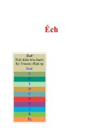
■
MICROMASTER 410 inverter
■
Filters and chokes
69
(2.72)
102
(4.02)
163 (6.44)
175 (6.89)
Ø 4.5
(0.18)
34.5
(1.36)
G_DA51_EN_05073
Inverter frame size AA
6SE6410-2 . . 11-2AA0
6SE6410-2 . . 12-5AA0
6SE6410-2 . . 13-7AA0
Inverter frame size AB
6SE6410-2 . . 15-5BA0
6SE6410-2 . . 17-5BA0
69
(2.72)
118
(4.65)
150 (5.9)
12
(0.47)
160 (6.30)
DA51-5036aA
Ø 4.5
(0.18)
DA51-5037a
69
(2.72)
138
(5.43)
Ø 4.5
(0.18)
12
(0.47)
160 (6.30)
150 (5.9)
A
All dimensions in mm (values in brackets are in inches)
Inverter with flat plate heatsink
6SE6410-2 . B13-7AB0
6SE6410-2 . B17-5BB0
Footprint chokes
6SE6400-3CC00-4AB3
6SE6400-3CC01-0AB3
Choke for upright mounting
6SE6400-3CC02-6BB3
75.5
(1.97)
200
50
(7.87)
G_DA51_EN_05104a
(2.97)
G_DA51_EN_05105a
(5.91)
50
(1.97)
(8.39)213
150
All dimensions in mm (values in brackets are in inches)
ADA51-5010e
2 x M4
160 (6.3)
56
73
200 (7.87)
174 (6.85)
187 (7.36)
(2.2)
(2.87)
42.5 (1.67)
23.5
(0.93)
Filter
6SE6400-2FL01-0AB0
Dimension drawings
Siemens DA 51.2 · 2005/2006
2/1
2
Inverter
MICROMASTER 420
2/2
Description
2/4
Circuit diagrams
2/6
Technical data
2/8
Selection and ordering data
2/9
Options
2/18
Dimension drawings
2/2
Siemens DA 51.2 · 2005/2006
MICROMASTER 420
2
■
Applications
■
Main characteristics
■
Options (overview)
■
International standards
The MICROMASTER 420 in-
verter is suitable for a variety
of variable-speed drive appli-
cations. It is especially suit-
able for applications with
pumps, fans and in conveyor
systems.
It is the ideal cost-optimized
frequency inverter solution.
The inverter is especially char-
acterized by its customer-ori-
ented performance and ease-
of-use. Its large mains voltage
range enables it to be used all
over the world.
■
Design
The MICROMASTER 420 in-
verter has a modular design.
The operator panels and com-
munication modules can be
easily exchanged without re-
quiring any tools.
■
Easy, guided start-up
■
Modular construction al-
lows maximum configura-
tion flexibility
■
Three fully programmable
isolated digital inputs
■
One analog input (0 V to
10 V, scaleable) or for use
as 4th digital input
■
One programmable analog
output (0 mA to 20 mA)
■
One programmable relay
output (30 V DC/5 A resis-
tive load; 250 V AC/2A in-
ductive load)
■
Low-noise motor operation
through high pulse frequen-
cy, adjustable (observe de-
rating if necessary)
■
Complete protection for
motor and inverter.
■
EMC filter, Class A/B
■
LC filter
■
Line commutating chokes
■
Output chokes
■
Gland plates
■
Basic Operator Panel
(BOP) for parameterizing
the inverter
■
Advanced Operator Panel
(AOP) with multi-language
plain text display
■
Asian Advanced Operator
Panel (AAOP) with Chinese
and English plain text dis-
play
■
Communication modules
– PROFIBUS
– DeviceNet
–CANopen
■
PC connection kits
■
Mounting kits for installing
the operator panels in the
control cabinet doors
■
PC start-up programs exe-
cutable under Windows 98
and NT/2000/ME/
XP Professional
■
TIA integration with
Drive ES
■
The MICROMASTER 420
inverter complies with the
requirements of the EU low-
voltage guideline
■
The MICROMASTER 420
inverter has the > mark-
ing
■
acc. to u and cu certified
■
c-tick
●
✔
Note:
See Appendix for standards.
Description
Siemens DA 51.2 · 2005/2006
2/3
MICROMASTER 420
2
■
Mechanical features
■
Performance features
■
Protection features
■
Modular design
■
Operating temperature
–10 °C to +50 °C
(+14 °F to +122 °F)
■
Compact housing as a re-
sult of high power density
■
Easy cable connection,
mains and motor connec-
tions are separated for opti-
mum electromagnetic com-
patibility
■
Detachable operator
panels
■
Screwless control terminals
■
Latest IGBT technology
■
Digital microprocessor
control
■
Flux Current Control (FCC)
for improved dynamic re-
sponse and optimized mo-
tor control
■
Linear V/f characteristic
■
Quadratic V/f characteristic
■
Multipoint characteristic
(programmable V/f charac-
teristic)
■
Flying restart
■
Slip compensation
■
Automatic restart following
mains failure or fault
■
Internal PI controller for sim-
ple process control
■
Programmable accelera-
tion/deceleration times
from 0 s to 650 s
■
Ramp smoothing
■
Fast Current Limit (FCL) for
trip-free operation
■
Fast, repeatable digital in-
put response time
■
Fine adjustment using a
high-resolution 10-bit ana-
log input
■
Compound braking for con-
trolled rapid braking
■
Four skip frequencies
■
Removable “Y” capacitor
for use on IT systems (with
non-grounded mains sup-
plies, the “Y” capacitor
must be removed and an
output choke installed).
■
Overload current 1.5 x rat-
ed output current (i.e.
150 % overload capability)
for 60 s, cycle time 300 s
■
Overvoltage/undervoltage
protection
■
Inverter overtemperature
protection
■
Motor protection using PTC
via digital input (possible
with supplementary circuit)
■
Earth fault protection
■
Short-circuit protection
■
I
2
t motor thermal protection
■
Locked motor protection
■
Stall prevention
■
Parameter interlock
Description
2/4
Siemens DA 51.2 · 2005/2006
MICROMASTER 420
2
■
General circuit diagram
PE
SI
PE
L/L1, N/L2
L/L1, N/L2, L3
L1, L2, L3
=
3
~
PE
U,V,W
M
A
D
+10 V
0 V
0 - 20 mA
max. 500 Ω
CPU
RS485
D
A
~
=
ADC+
ADC-
DIN1
DIN2
DIN3
DAC+
DAC-
P+
N-
RL1-B
RL1-C
1
2
3
4
5
6
7
8
9
12
13
14
15
10
11
≥ 4,7 k Ω
DC+
DC
−
DIN4
2
3
4
9
24 V
–
+
12
60 Hz
50 Hz
150.00
DIN1
DIN2
DIN3
5
6
7
9
NPN
PNP
24 V
+
_
BOP/AOP
RS232
1/3 AC 200 - 240 V
3 AC 380 - 480 V
G_DA51_EN_00011
Not
used
Output
0 V
max. 100 mA
(
isolated
)
30 V DC/5 A (
resistive load
)
250 V AC/2 A (
inductive load
)
Output
+24 V
max. 100 mA
(
isolated
)
or
or
automatic
DC link
The analog input can be used
as an additional digital input
(DIN4)
DIP switch
or
24 V external
BOP link
COM link
Relay
CB
option
Circuit diagrams
Siemens DA 51.2 · 2005/2006
2/5
MICROMASTER 420
2
■
Terminal connection diagram
57869
1342
10 11
RL1-B RL1-C
+10 V 0 V ADC+ ADC-
12 14 1513
DAC+ DAC- P+ N-
DIN1 DIN2 DIN3 +24 V 0 V
NPN
PNP
Output relay
RL1
Analog output
RS-485
(USS protocol)
Voltage
supply 10 V
Analog input
Output relay contacts
Digital inputs PNP or NPN
possible
(isolated)
G_DA51_EN_05106
View A
View A
Mains
connections
Motor
connections
DC link
terminals
Example frame size A
Circuit diagrams