Tài liệu Next Generation Enterprise MPLS VPN-Based WAN Design and Implementation Guide doc
Bạn đang xem bản rút gọn của tài liệu. Xem và tải ngay bản đầy đủ của tài liệu tại đây (1.98 MB, 80 trang )
Americas Headquarters
Cisco Systems, Inc.
170 West Tasman Drive
San Jose, CA 95134-1706
USA
Tel: 408 526-4000
800 553-NETS (6387)
Fax: 408 527-0883
Next Generation Enterprise MPLS
VPN-Based WAN Design and
Implementation Guide
Cisco Validated Design I
October 1, 2007
Cisco Validated Design
The Cisco Validated Design Program consists of systems and solutions designed, tested, and
documented to facilitate faster, more reliable, and more predictable customer deployments. For more
information visit www.cisco.com/go/validateddesigns
.
ALL DESIGNS, SPECIFICATIONS, STATEMENTS, INFORMATION, AND RECOMMENDATIONS (COLLECTIVELY,
"DESIGNS") IN THIS MANUAL ARE PRESENTED "AS IS," WITH ALL FAULTS. CISCO AND ITS SUPPLIERS DISCLAIM
ALL WARRANTIES, INCLUDING, WITHOUT LIMITATION, THE WARRANTY OF MERCHANTABILITY, FITNESS FOR A
PARTICULAR PURPOSE AND NONINFRINGEMENT OR ARISING FROM A COURSE OF DEALING, USAGE, OR TRADE
PRACTICE. IN NO EVENT SHALL CISCO OR ITS SUPPLIERS BE LIABLE FOR ANY INDIRECT, SPECIAL,
CONSEQUENTIAL, OR INCIDENTAL DAMAGES, INCLUDING, WITHOUT LIMITATION, LOST PROFITS OR LOSS OR
DAMAGE TO DATA ARISING OUT OF THE USE OR INABILITY TO USE THE DESIGNS, EVEN IF CISCO OR ITS SUPPLIERS
HAVE BEEN ADVISED OF THE POSSIBILITY OF SUCH DAMAGES.
THE DESIGNS ARE SUBJECT TO CHANGE WITHOUT NOTICE. USERS ARE SOLELY RESPONSIBLE FOR THEIR
APPLICATION OF THE DESIGNS. THE DESIGNS DO NOT CONSTITUTE THE TECHNICAL OR OTHER PROFESSIONAL
ADVICE OF CISCO, ITS SUPPLIERS OR PARTNERS. USERS SHOULD CONSULT THEIR OWN TECHNICAL ADVISORS
BEFORE IMPLEMENTING THE DESIGNS. RESULTS MAY VARY DEPENDING ON FACTORS NOT TESTED BY CISCO.
Any Internet Protocol (IP) addresses used in this document are not intended to be actual addresses. Any examples, command display output, and figures included in the
document are shown for illustrative purposes only. Any use of actual IP addresses in illustrative content is unintentional and coincidental.
Next Generation Enterprise MPLS VPN-Based WAN Design and Implementation Guide
© 2007 Cisco Systems, Inc. All rights reserved.
CCVP, the Cisco Logo, and the Cisco Square Bridge logo are trademarks of Cisco Systems, Inc.; Changing the Way We Work, Live, Play, and Learn is a service mark of Cisco Systems,
Inc.; and Access Registrar, Aironet, BPX, Catalyst, CCDA, CCDP, CCIE, CCIP, CCNA, CCNP, CCSP, Cisco, the Cisco Certified Internetwork Expert logo, Cisco IOS, Cisco
Press, Cisco Systems, Cisco Systems Capital, the Cisco Systems logo, Cisco Unity, Enterprise/Solver, EtherChannel, EtherFast, EtherSwitch, Fast Step, Follow Me Browsing,
FormShare, GigaDrive, GigaStack, HomeLink, Internet Quotient, IOS, iPhone, IP/TV, iQ Expertise, the iQ logo, iQ Net Readiness Scorecard, iQuick Study, LightStream,
Linksys, MeetingPlace, MGX, Networking Academy, Network Registrar, Pac ke t, PIX, ProConnect, RateMUX, ScriptShare, SlideCast, SMARTnet, StackWise, The Fastest Way
to Increase Your Internet Quotient, and TransPath are registered trademarks of Cisco Systems, Inc. and/or its affiliates in the United States and certain other countries.
All other trademarks mentioned in this document or Website are the property of their respective owners. The use of the word partner does not imply a partnership relationship
between Cisco and any other company. (0612R)
iii
Next Generation Enterprise MPLS VPN-Based WAN Design and Implementation Guide
CONTENTS
CHAPTER
1
Solution Description
1-1
CHAPTER
2
Deployment Architectures
2-1
WAN Core
2-1
MPLSoL2 Service
2-1
MPLSoGRE
2-2
Carrier Supporting Carrier (CSC)
2-4
WAN Edge
2-5
WAN Edge Integration
2-6
Multi-VPN Service from Provider
2-7
Carrier Supporting Carrier
2-7
MPLSoL2 Service
2-8
DMVPN per VRF
2-9
MPLS VPN over DMVPN—2547oDMVPN (Hub & Spoke Only)
2-11
Hub as a P Router
2-12
Hub as a PE Router
2-13
MPLS VPN Over IP Using L2TPv3—2547oL2TPv3
2-13
CHAPTER
3
WAN Core—MPLSoL2 Service
3-1
Platforms
3-1
CHAPTER
4
WAN Edge—MPLSoL2 Service
4-1
Platforms
4-2
Multicast
4-4
QoS
4-5
Voice and VRFs
4-7
Voice in a VRF at the Branch
4-7
Voice Global at the Branch
4-8
System Scale and Performance Considerations
4-8
CHAPTER
5
WAN Edge—DMVPN Per VRF
5-1
Platforms
5-1
Contents
iv
Next Generation Enterprise MPLS VPN-Based WAN Design and Implementation Guide
Building Redundancy
5-4
Implementing Multicast
5-8
Implementing QoS
5-9
Scale Considerations
5-10
Voice and VRFs
5-11
Voice in a VRF at the Branch
5-11
Voice Global at the Branch
5-11
CHAPTER
6
WAN Edge—MPLS VPN over DMVPN—2547oDMVPN (Hub and Spoke Only)
6-1
Platforms
6-2
Hub and Spoke Communication
6-2
Spoke-to-Spoke Communication (via Hub)
6-6
Connecting to the Core MPLS Network
6-11
Building Redundancy
6-11
Understanding Convergence
6-14
Single-Tier Branches—Backup Tunnel on the Same Router
6-14
Dual-Tier Branches—Backup Tunnel on Different Routers
6-15
Convergence Time When BGP Default Timer is Used
6-15
Implementing Multicast
6-16
Implementing QoS
6-20
MTU Issues
6-24
Voice and VRFs
6-25
Voice in a VRF at the Branch
6-25
Voice Global at the Branch
6-26
Scale Considerations
6-28
Solution Caveats Summary
6-28
CHAPTER
7
Migration Strategy and Integrating Non-VRF Sites
7-1
CHAPTER
1-1
Next Generation Enterprise MPLS VPN-Based WAN Design and Implementation Guide
1
Solution Description
Enterprise customers have in the past relied heavily upon traditional WAN/MAN services for their
connectivity requirements. Layer 2 circuits based on TDM, Frame Relay, ATM, and SONET have
formed the mainstay of most low-speed WAN services. More recently, high-speed MAN solutions have
been delivered directly over Layer 1 optical circuits, SONET, or through the implementation of
point-to-point or point-to-multipoint Ethernet services delivered over one of these two technologies.
Today, many enterprise customers are turning to Multiprotocol Label Switching (MPLS)-based VPN
solutions because they offer numerous secure alternatives to the traditional WAN/MAN connectivity
offerings. The significant advantages of MPLS-based VPNs over traditional WAN/MAN services
include the following:
•
Provisioning flexibility
•
Wide geographical availability
•
Little or no distance sensitivity in pricing
•
The ability to mix and match access speeds and technologies
•
Perhaps most importantly, the ability to securely segment multiple organizations, services, and
applications while operating a single MPLS-based network
Although service providers have been offering managed MPLS-based VPN solutions for years, the larger
enterprises, universities, and federal and state governments are now beginning to investigate and deploy
MPLS in their own networks to implement self-managed MPLS-based VPN services. The concept of
self-managed enterprise networks is not new; many enterprise customers purchase Layer 2 TDM, Frame
Relay, or ATM circuits and deploy their own routed network for these circuits. The largest of enterprise
customers even manage their own core networks by implementing Frame Relay or ATM-based switching
infrastructures and “selling” connectivity services to other organizations within their companies.
Both of these solutions have had disadvantages; deploying an IP-based infrastructure over leased lines
offers little flexibility and segmentation capabilities that are cumbersome at best. Deploying a switched
Frame Relay or ATM infrastructure to allow for resiliency and segmentation is a solution within reach
of only the largest and most technically savvy enterprises.
As noted, the self-managed MPLS-based network is typically reserved for larger enterprises willing to
make an investment in network equipment and training, with an IT staff that is comfortable with a high
degree of technical complexity. A self-managed MPLS VPN can be an attractive option if a business
meets these requirements and wants to fully control its own WAN or MAN and to increase virtualization
across multiple sites to guarantee delivery of specific applications. There are alternate approaches to
full-fledged MPLS implementations such as Multi-VRF or a combination of both MPLS and Multi-VRF
that allow existing networks to be easily transitioned to virtualized ones. The level of security between
separated networks is comparable to private connectivity without needing service provider intervention,
allowing for consistent network segmentation of departments, business functions, and user groups.
1-2
Next Generation Enterprise MPLS VPN-Based WAN Design and Implementation Guide
Chapter 1 Solution Description
Corporations with a propensity for mergers and acquisitions benefit from the inherent any-to-any
functions of MPLS that, when the initial configuration is completed, allow even new sites with existing
networks to be merged with the greater enterprise network with minimal overhead. Secure partner
networks can also be established to share data and applications as needed, on a limited basis.
Theself-managed MPLS is also earning greater adoption as an important and viable method for meeting
and maintaining compliance with regulatory privacy standards such as HIPAA and the Sarbanes-Oxley
Act.
While the technology enables you to create the logical separation across networks, it is important to
understand the reasons for creating these logical networks. Enterprise customers increasingly require
segmentation for a number of different reasons:
•
Closed User Groups (CUG)—The CUGs could be created based on a number of different business
criteria, with guest Internet access for onsite personnel being the simplest example. Providing
NAC/isolation services also creates a need to separate the non-conforming clients. While this can
be done using VLANs within a Layer 2 campus network, it requires Layer 3 VPN functionality to
extend it across Layer 3 boundaries. CUGs could be created with partners, either individually or as
a sub-group, where the segmentation criteria are resources that are to be shared/accessed. This
simplifies the information sharing with partners while still providing security and traffic separation.
•
Virtualization—Segmentation to the desktop is driving virtualization in the application server space.
This means that even existing employees can be segmented into different CUGs where they are
provided access to internal services based on their group membership.
•
Enterprise as a Service Provider—With some of the enterprise networks expanding as their
organization expands, IT departments at some of the large enterprises have become internal Service
Providers. They leverage a shared network infrastructure to provide network services to individual
Business Units within the enterprise. This not only requires creating VPNs, but also requires the
ability of each of the BUs to access shared corporate applications. Such a model can be expanded to
include scenarios in which a company acquires another company (possibly with an overlapping IP
addressing scheme) and needs to eventually consolidate the networks, the applications, and the
backoffice operations.
•
Protecting critical applications—Another segmentation criteria could be based off the applications
themselves rather than the users. An organization that feels that its critical applications need to be
separated from everyday network users can create VPNs for each or a group of applications. This
not only allows it to protect them from any malicious traffic, but also more easily control user access
to the applications. An example of this is creating separate VPNs for voice and data.
Beyond the segmentation criteria, the overarching consideration should be based on the need to share.
The VPNs create a closed user group that can easily share information, but there will always be the
scenario that requires sharing across the VPNs. For example, a company-wide multicast stream would
need to be accessible by all the employees irrespective of their group association. Thus the VPNs should
be created based on practical considerations that conform to the business needs of the organization.
The first phase of the solution provided design guidelines for creating a self deployed MPLS MAN for
the enterprise. It focused on Layer 3 VPNs and Layer 2 VPNs deployments, multicast and voice services
supported by a end-to-end QoS model. It provided models for shared services deployments such as
Internet access.
The next logical step for expanding virtualization across enterprise networks is to extend it into two other
areas (
Figure 1-1):
•
Connecting large MAN/campus MPLS networks
•
Remote branches
1-3
Next Generation Enterprise MPLS VPN-Based WAN Design and Implementation Guide
Chapter 1 Solution Description
Figure 1-1 NGMAN/WAN 2.0—Solution Scope
While the MAN deployment in phase 1.0 was characterized by higher bandwidth requirements, WAN
deployment (especially branch aggregation) is characterized by higher scale requirements to support
100s to 1000s of sites. A WAN may be a Layer 2 or Layer 3 service and may be spread across providers.
A Layer 3 WAN may require some form of overlay network to support enterprise virtualization. The
virtualization deployment in the WAN also has a important bearing on how the sites are integrated with
the core MPLS network.
The remaining chapters explore the different deployment models for inter-MAN MPLS connectivity and
virtualized branch aggregation. It focuses on data, voice, and multicast services along with QoS. Each
of the models is discussed with lab tested and deployable examples.
For a technology refresher and MPLS MAN deployment, refer to the phase 1.0 DIG:
MAN1
Data
Center
Multiple MPLS MAN/
Large Campus
Virtualized Branches
Single or Multi-
SP Network
L2/L3 Service
Campus
MAN2
Data
Center
Branch1
SP1
SP2
SP3
Branch4
Branch2
Branch3
221591
1-4
Next Generation Enterprise MPLS VPN-Based WAN Design and Implementation Guide
Chapter 1 Solution Description
CHAPTER
2-1
Next Generation Enterprise MPLS VPN-Based WAN Design and Implementation Guide
2
Deployment Architectures
As mentioned earlier, network virtualization extension across the WAN can be broadly classified into
two categories:
•
Inter-MAN/ large campus connectivity or WAN core
•
Virtualized branch aggregations or WAN edge
WAN Core
After creating MPLS MAN islands, this is the next logical step when migrating to MPLS-based
enterprise networks. The different options for interconnecting MPLS MANs are:
•
MPLSoL2 service—If it is a legacy Layer 2 or Layer 2 VPN service from SP
•
MPLSoGRE—If it is a Layer 3 VPN service from SP
•
Carrier Supporting Carrier (CSC)
Typically, in a large enterprise, the WAN core consists of dedicated point-to-point, high-bandwidth links.
We do not expect these to move to Layer 3-based (such as Layer 3 VPNs) connections because these are
deemed critical links that require the fastest possible round-trip times and higher bandwidths —hence
Layer 2circuits are preferred. Additionally, these are few in numbers and hence cost advantages of Layer
3 services are not necessarily applicable.
While all three options are discussed in this chapter, only MPLSoL2 Service is discussed in depth in
WAN Core—MPLSoL2 Service since it is expected to be the most-widely deployed.
MPLSoL2 Service
This is the simplest deployment model for connecting MANs if the enterprise already has Layer 2
connectivity between them either via legacy WAN (FR/ATM/POS) or via Layer 2 VPN service (AToM)
from a provider. The migration involves converting the edge devices into a P/PE and making it part of
the MPLS MAN network.
The MANs are assumed to be already MPLS enabled and configured for enterprise-deployed VPNs. As
shown in
Figure 2-1, the WAN edge router used for interconnecting MANs plays the role of a P device.
It is expected to label switch packets between the MANs across the SP network.
2-2
Next Generation Enterprise MPLS VPN-Based WAN Design and Implementation Guide
Chapter 2 Deployment Architectures
WAN Core
Figure 2-1 MPLS Over Legacy Layer 2 Service
Figure 2-2 MPLS Over Layer 2 VPN Service
From a control plane perspective, the following are expected to be run over the Layer 2 link:
•
IGP such as EIGRP or OSPF for MPLS device reachability (P/PE/RR)
•
LDP for label distribution
•
MP-iBGP for VPN route/label distribution
If these MAN islands/campuses are under different administrative control, then Inter-AS can be
implemented. Typical Inter-AS models are:
•
Back-to-back VRFs
•
ASBR-to-ASBR with MP-eBGP
•
ASBR-to-ASBR with multihop EBGP using Route Reflectors
Apart from being a simple solution to deploy, it also offers wider platform options. All the platforms that
support P roles should be deployable. All the features that would be deployed within a MPLS network
(such as TE) can also be deployed across the WAN core.
MPLSoGRE
The implementation assumes that the enterprise has a Layer 3-based service such a Layer 3 VPNs from
a provider interconnecting the MPLS MANs. The MANs may have multiple connections between them
to provide load balancing and/or redundancy. It might be desirable to obtain the redundant connectivity
services from multiple providers.
MAN1
SP
Network
E-P
RR
E-P
E-PE
E-PE
MAN2
E-P
RR
E-P
E-PE
E-PE
FR/ATM Switch FR/ATM Switch
221592
MAN1
SP
Network
E-P
RR
E-PE-PE
E-PE
MAN2
E-P
RR
E-P
E-PE
E-PE
P-PE
AToM
AToM
P-PE
P-PE P-PE
221593
2-3
Next Generation Enterprise MPLS VPN-Based WAN Design and Implementation Guide
Chapter 2 Deployment Architectures
WAN Core
As shown in Figure 2-3, the WAN edge router used for interconnecting MANs plays the role of a P
device even though it is a CE for the SP VPN service. It is expected to label switch packets between the
MANs across the SP network.
Figure 2-3 MPLS over GRE
A point-to-point GRE tunnel is set up between each edge router pair (if full mesh is desired). From a
control plane perspective, the following are expected to be run within the GRE tunnels:
•
IGP such as EIGRP or OSPF for MPLS device reachability (P/PE/RR)
•
LDP for label distribution
•
MP-iBGP for VPN route/label distribution
Once the route/label distribution is done in the control plane, the enterprise edge device acts like a label
switching router (LSR/P) where it treats the GRE interfaces as normal access interfaces.
Figure 2-4
shows end-to-end packet flow between campuses across different MANs.
Figure 2-4 MPLS over GRE—Forwarding Plane
As can be seen from the headers, this adds a large amount of overhead to the MTU and hence is not the
most desired option. In addition, platform support is also limited to the 7200 and ISRs. Thus none of the
high-end platforms (7600, 12000) support it. 7600 supports MPLSoGRE in PE-PE mode only, but
ideally we would prefer P-P setup for inter-MAN connectivity. Thus MPLSoGRE is not a preferred
option for Inter-MAN connectivity.
MAN1
SP
Network
E-P
RR
E-PE-PE
E-PE
MAN2
E-P
RR
E-P
E-PE
E-PE
P-PE
GRE
GRE
P-PE
P-PE P-PE
221594
IP1
LDP1
VPN
IP1
LDP1
VPN
IP1
LDP3
VPN
IP1
LDP3
VPN
IP1IP1 IP1IP1 IP1
LDP2
IP2
GRE
VPN
IP1
LDP2
IP2
GRE
VPN
IP1
LDP2
IP2
GRE
VPN
IP1
LDP2
IP2
GRE
VPN
IP1
LDP2
IP2
GRE
VPN
SP VPN
SP LDP
IP1
LDP2
IP2
GRE
VPN
SP VPN
SP LDP
E-PE E-P P-PE P-PE E-P E-PE
SP VPN MAN2MAN1
221595
2-4
Next Generation Enterprise MPLS VPN-Based WAN Design and Implementation Guide
Chapter 2 Deployment Architectures
WAN Core
Carrier Supporting Carrier (CSC)
The Carrier Supporting Carrier was developed for MPLS enabled SPs to support other MPLS/VPN SPs.
With the growth in enterprise network growth, CSC is a service that SPs can provide to large enterprises
as well. For an enterprise, this involves getting a label transport service from a provider. The enterprise
edge devices perform the P role in the enterprise MPLS network.
The advantages of a label transport service include the fact that there is no overlay such as GRE required.
The SP provides any-to-any connectivity as well, so multiple dedicated links are not required between
the MANs. Based on the incoming label, the SP network ensures that the packet is forwarded to the
correct MAN location.
From a control plane perspective there are two major elements (Figure 2-5):
1.
A IPv4 route and label exchange between the enterprise edge P and the Provider PE—the only routes
that needed to be exchanged are for the PE and RR reachability (loopbacks). This can be achieved
in two ways:
a.
Running a IGP with the Provider PE to advertise the loopback addresses and running LDP to
advertise the labels associated with those loopback addresses.
b.
Alternatively, the SP may prefer to run EBGP+label option to advertise the loopback addresses
along with their associated labels.
2.
Enterprise running MP-iBGP between its RRs to exchange VPNv4+lable information for its own
VPNs.
Figure 2-5 Carrier Supporting Carrier (CSC)
In the forwarding plane, as shown in Figure 2-6, the following occurs:
•
The P router at the enterprise edge (E-P1) receives a labeled packet from the MAN and label
switches it based on the label learned via the provider for E-P2.
•
The provider PE (P-PE1) label switches the incoming top label with the label advertised via P-PE2.
This is treated as the “VPN” label within the provider network.
•
P-PE1 prepends the top label (SP LDP) for P-PE1 to P-PE2 reachability.
•
P-PE2 receives the packet with SP LDP label popped (if PHP is enabled). It label switches the
exposed label corresponding to the one advertised by E-P2.
MAN1
SP MPLS
Network
RR
E-PE-PE
E-PE
MAN2
RR
E-P
E-PE
E-PE
P-PE
P-PE
221596
IGP + LDP
IGP + LDP
1. IPv4 routes (E-PE loopback)
with label distribution
2. MP-iBGP for
Enterprise VPNv4
2-5
Next Generation Enterprise MPLS VPN-Based WAN Design and Implementation Guide
Chapter 2 Deployment Architectures
WAN Edge
•
E-P2 label switches the top label and sends it across the MAN2 network to the appropriate PE.
Figure 2-6 Carrier Supporting Carrier—Forwarding Plane
Depending on the size of the deployments, the platforms can range from 12000, 7600, 7304, 7200, or
3800.
CSC does have two major draw backs:
•
There is a very limited offering from the SPs to the enterprises—their CSC service is designed
primarily for other SPs. Additionally, since the VPNs are now maintained by the enterprises, the SP
essentially sells a single VPN service.
•
Since it is essentially a Layer 3 service from a provider, the enterprise may wish to encrypt the
traffic, which is not feasible as currently there are no mechanisms that allow for encryption of
labelled packets.
WAN Edge
If enterprises have requirements for virtualization of the branches, then the following deployment
models are technically available:
•
Multi-VPN service from SP
•
Carrier Supporting Carrier
•
MPLSoL2 infrastructure
•
Self-Deployed Multi-VRF with mGRE/DMVPN (DMVPN per VRF)
•
MPLS VPN over DMVPN— 2547oDMVPN (Hub and Spoke only)
•
MPLS VPN over IP using L2TPv3 (2547oL2TPv3)
There are scenarios where virtualization may be required at the large branches only. The rest of the
branches may not have any VRFs, but may have to be placed in there own VRF, default common VRF,
or global table at the headend depending on enterprise requirements.
The deployment models should support integration of branches ranging from 10s to 1000s. The interface
types on the headend are expected to range from the DS3 to GE. The speeds on the branches would
typically be T1 or below.
IP1
LDP1
VPN
IP1
LDP1
VPN
IP1
LDP3
VPN
IP1
LDP4
VPN
IP1IP1 IP1IP1 IP1
LDP2
VPN
IP1
LDP3
VPN
IP1
LDP2
VPN
IP1
LDP2
VPN
IP1
VPN
SP VPN
SP LDP
IP1
VPN
SP VPN
SP LDP
E-PE E-P P-PE P-PE E-P E-PE
SP VPN MAN2MAN1
221597
2-6
Next Generation Enterprise MPLS VPN-Based WAN Design and Implementation Guide
Chapter 2 Deployment Architectures
WAN Edge
WAN Edge Integration
The deployment models listed above allow connectivity between the segmented branches and the
headend. The headend itself (as shown in
Figure 2-7) may be connected to the rest of the core network
in at least three different ways (discussed below). Not every model may support these integration
options.
Figure 2-7 Integrating WAN Edge with MPLS MAN
1.
Direct connectivity with campus—In this scenario the WAN edge router is running in VRF-lite
mode towards the campus where the VRFs from the branches are extended into the campus by using
VLANs. The assumption here is that campus is virtualized using a combination of VLANs and
VRF-lite as well. A separate routing instance is running per VRF within the campus that is extended
to the branches via the WAN edge device. This can be deployed with any of the deployment models
above.
SP
Network
L2/L3
Service
Remote
Branches
Enterprise
B-PE3B-PE1
B-PE2
221598
WAN-
PE/P
MPLS
MAN
MAN-PE1
MAN-PE2
RR
P
MPLS
MAN
Campus
MAN-PE2
MAN-PE1
RR
P
1
2
3
2-7
Next Generation Enterprise MPLS VPN-Based WAN Design and Implementation Guide
Chapter 2 Deployment Architectures
WAN Edge
2.
Back-to-back PEs with MPLS MAN—The WAN edge router is running VRF-lite mode towards the
core network in this scenario as well, but instead of connecting into a VRF-lite campus, it connects
back-to-back with a MPLS MAN PE. This option is ideal for scenarios where the WAN Edge router
may have P capabilities to extend the core MPLS to the branches or if it cannot be directly made
into a core PE. This option can be deployed with any of the models above.
3.
Direct Connectivity with MPLS MAN—This is the easiest integration option since the WAN edge
router performs the P functionality and the branch PEs are integrated directly with the core MPLS
network. This is ideal for MPLSoL2 and 2547oDMVPN deployments although its currently not
supported fully in the later scenario.
Multi-VPN Service from Provider
A simple solution for enterprises to extend virtualization to the branches is to obtain multiple Layer 3
VPN services from a provider. As shown in
Figure 2-8, the branch routers become Multi-VRF CEs and
the headend may be a Multi-VRF CE or a PE (if it is directly connected to the MPLS MAN). This may
be a desirable solution from a cost perspective if there are a small number of branches that have a
requirement for virtualization and the number of VRFs is low.
Figure 2-8 Multi-VPN service from SP
In the control plane each of the CEs run a routing protocol such as OSPF, EIGRP or BGP with the SP
PE on per VRF basis. Thus any design recommendations implemented while getting a single VPN
service (in terms of routing, QoS, Multicast, etc.) would have to be followed for each of these VPN
instances as well.
Carrier Supporting Carrier
This is same labeled transport service that was discussed in Carrier Supporting Carrier (CSC). The
requirement here is limited to branch routers such as ISRs.
SP L3VPN
Service
MPLS
MAN
RR
E-PE
Remote
Branches
Multi-
VRF CE
Multi-
VRF CE
Multi-
VRF CE
Subinterface/VPN
221599
2-8
Next Generation Enterprise MPLS VPN-Based WAN Design and Implementation Guide
Chapter 2 Deployment Architectures
WAN Edge
MPLSoL2 Service
This model assumes that the enterprise has existing Layer 2 services for connecting branches and wants
to enable MPLS over them. Since such Layer 2 connectivity is typically hub and spoke or partial mesh,
the MPLS overlay also inherits the same connectivity characteristics. If spoke-to-spoke communication
is required, it has to be handled via the hub.
The branch aggregation router is converted into a P role for the MPLS network and is expected to label
switch packets as shown in
Figure 2-9. The branch routers become PE routers with VRF interfaces facing
the branch and MPLS-enabled interface facing the headend.
Figure 2-9 MPLSoL2 Service
In the control plane, each of the remote branch PEs would have a LDP session and a IGP session with
the headend aggregator. They would also have MP-iBGP sessions with the route reflectors that would
typically reside behind the headend aggregating device.
In cases where virtualization is not required at certain branches, then those branch routers do not need
to have their WAN connection MPLS enabled. On the headend, depending on the connectivity model
(point-to-point vs. multipoint) and interface flexibility, the enterprise has a few options:
•
If using multipoint interface(s) at headend, then separate the MPLS-enabled and the non-MPLS
connections into separate multipoint groups. Within the non-MPLS group, they may need to be
further separated based on the VRF(s) into which they need to be placed.
•
If using point-to-point interfaces, then each individual connection can be MPLS enabled or placed
in a VRF.
•
A combination of point-to-point and multipoint interfaces can be supported as well.
MPLS
MAN
RRRR
SP L2
Service
E-P
Remote
Branches
E-PEE-PE
E-PE
E-PE
MPLS
Enabled
Links
221600
2-9
Next Generation Enterprise MPLS VPN-Based WAN Design and Implementation Guide
Chapter 2 Deployment Architectures
WAN Edge
Note
In each of the cases, the aggregation device have to perform both the roles—P as well as PE.
DMVPN per VRF
This model can be used over a Layer 2 or Layer 3 service from a provider. If it is a Layer 3 VPN service,
then the enterprise purchases only a single VPN from the provider but overlays its own VPNs by using
a combination of Multi-VRF and GRE. The headend has a mGRE tunnel per VRF, the branches have
either GRE (if no spoke-to-spoke communication is required) or mGRE (if spoke-to-spoke
communication is required) tunnels per VRF. DMVPN provides for spoke-to-spoke communication as
well as encryption (although encryption is optional for our deployment model). By configuring mGRE
on certain spokes, it provides them with the ability to create dynamic tunnels to other spokes (which
should be configured with mGRE as well) on a per-VRF basis.
Most enterprises only have a partial mesh requirement—large sites need to be meshed together but the
smaller sites are typically only hub and spoke. Thus the deployment is expected to be a combination of
GRE and mGRE at the spokes (
Figure 2-10).
Figure 2-10 DMVPN per VRF
The hub device, while aggregating the branches, is also a PE for the MPLS MAN network. It has a IGP
instance running within each VPN with each of the spokes. The IPv4 addresses learned from the spokes
are converted to VPNv4 addresses before being advertised to the RRs using MP-iBGP. IGP might limit
the scale of the deployment requiring the use of multiple hub routers. Scaling options include:
•
Use of BGP as the hub and spoke protocol with dedicated RRs for this purpose
MPLS
MAN
RR
SP
Network
E-PE
Remote
Branches
Multi-
VRF CE
Multi-
VRF CE
Multi-
VRF CE
Multi-
VRF CE
mGRE
per VRF
MP-iBGP for
VPNv4 routes
IGP per VRF
221601
2-10
Next Generation Enterprise MPLS VPN-Based WAN Design and Implementation Guide
Chapter 2 Deployment Architectures
WAN Edge
•
Having multiple termination devices at the headend based—for example, one for each VRF if there
are a low number of VRFs
DMVPN uses NHRP to keep track of the next-hop to physical address mapping. The hub is the NHRP
server that maintains the mapping table on per VRF basis. In the example shown in
Figure 2-11, once
the GRE tunnel is established with the hub, both Branch1 (CE1) and Branch2 (CE2) register with the
hub (E-PE1) using NHRP on per VRF basis. The hub learns about each of the branch VPN routes and
advertises them back out to the other branches.
Figure 2-11 DMVPN per VRF—Spoke-to-Spoke Communication
As shown in Figure 2-11, in the forwarding plane, the following sequence occurs on a per-VRF basis:
1.
A sends packets to CE1 destined for B.
2.
CE1 looks up its VRF table and finds B with next hop of CE2’s GRE tunnel address.
3.
CE1 sends a NHRP query to E-PE1 to resolve the next-hop address.
4.
E-PE1 looks up the per-VRF NHRP database and associates CE2’s tunnel address with its physical
interface address.
5.
E-PE1 sends the NHRP response back to CE1 with CE2’s physical interface address.
6.
CE1 sets up the dynamic GRE tunnel with CE2.
Figure 2-12 shows the end-to-end packet encapsulation when using this model. The packets from the
remote branches are encapsulated in GRE on a per-VRF basis and forwarded across the SP network. The
enterprise PE at the hub site decapsulates the GRE headers and performs label pushing based on the VRF
in which the GRE interface is configured. The packets are then forwarded as normal MPLS VPN packets
across the MAN (with the VPN and the LDP label).
MPLS
MAN
SP
Network
E-PE1
Branches
221602
CE2CE1
BA
1
2
3
5
4
6
2-11
Next Generation Enterprise MPLS VPN-Based WAN Design and Implementation Guide
Chapter 2 Deployment Architectures
WAN Edge
Figure 2-12 DMVPN per VRF—Forwarding Plane
The hub site PE can be a 7600 or a 7200 depending on the scale or encryption requirements. The spokes
can be aa ISR such as 2800 and 3800 depending on the branch requirements in terms of number of VRFs,
throughput, and other non-transport related features.
MPLS VPN over DMVPN—2547oDMVPN (Hub & Spoke Only)
This model does not have some of the scale limitations of the Multi-VRF based solutions because the
GRE tunnels are created outside the VRFs and hence a single tunnel can be shared for transporting many
VRFs. The hub is configured with a single mGRE tunnel while spokes have a single GRE tunnel.
Note
This is designed to be used for hub and spoke communication only and currently the dynamically created
spoke-to-spoke tunnels are not supported.
IP1IP1 IP1
LDP3
VPN
IP1
LDP1
VPN
IP1IP1IP1
IP2
GRE
IP1
IP2
GRE
IP1
IP2
GRE
IP1
IP2
GRE
IP1
IP2
GRE
IP1
IP2
GRE
Multi-VRF CE
L2
Service
from SP
L3 VPN
Service
from SP
E-PE E-PE
SP
Network
MAN1
Branch1
IP1IP1 IP1
LDP3
VPN
IP1
LDP1
VPN
IP1IP1IP1
IP2
GRE
IP1
IP2
GRE
IP1
IP2
GRE
IP1
IP2
GRE
IP1
IP2
GRE
SP VPN
SP LDP
IP1
IP2
GRE
SP VPN
SP LDP
221603
2-12
Next Generation Enterprise MPLS VPN-Based WAN Design and Implementation Guide
Chapter 2 Deployment Architectures
WAN Edge
Figure 2-13 2547oDMVPN (Hub & Spoke Only)
As shown in Figure 2-13, in the control plane the following protocols exist:
•
Routing protocol of the provider to learn the Branch and headend’s physical interface addresses
(tunnel source address). Statics could be used as well if these are easily summarizable.
•
GRE tunnel between the branch PE and the headend P.
•
IGP running in the enterprise global space over the GRE tunnel to learn remote PE’s and RR’s
loopback address.
•
LDP session over the GRE tunnel with label allocation/advertisement for the GRE tunnel address
by the branch router.
•
MP-iBGP session with RR, where the branch router’s BGP source address is the tunnel interface
address—this forces the BGP next-hop lookup for the VPN route to be associated with the tunnel
interface.
Additionally, IPsec can be used to encrypt the GRE tunnels; encryption happens after the GRE
encapsulation.
Hub as a P Router
As shown in Figure 2-14, the branch router attaches the appropriate VPN label for the destination along
with the LDP label advertised by the hub P for the destination next-hop address. It then encapsulates the
labeled packet in a GRE tunnel with the hub P as the destination before sending it to the provider. Since
in this example SP is providing Layer 3 VPN service, it further prepends its own VPN and LDP labels
for transport within its network. The hub P receives a GRE encapsulated labeled packet. It decapsulated
the tunnel headers before label switching it out to the appropriate outgoing interface in the MPLS MAN
for the packet to reach the eventual PE destination.
MPLS
MAN
RR
SP
Network
E-PE
Remote
Branches
E-PEE-PE
E-PEE-PE
mGRE
GRE/mGRE
IGP
and
LDP
IGP
and
LDP
over
GRE
221604
MP-iBGP for
VPNv4 routes
2-13
Next Generation Enterprise MPLS VPN-Based WAN Design and Implementation Guide
Chapter 2 Deployment Architectures
WAN Edge
Figure 2-14 2547oDMVPN—Forwarding Plane with Hub as a P
Hub as a PE Router
As shown in Figure 2-15, the branch router attaches the appropriate VPN label for the destination
advertised by the hub PE router. It then encapsulates the labeled packet in a GRE tunnel with the hub PE
as the destination before sending it to the provider. Since in this example SP is providing Layer 3 VPN
service, it further prepends its own VPN and LDP labels for transport within its network. The hub PE
receives a GRE encapsulated labeled packet. It decapsulated the tunnel headers before forwarding it out
to the appropriate outgoing interface based on the VPN label information and the VRF routing table.
Figure 2-15 2547oDMVPN—Forwarding Plane with Hub as a PE
MPLS VPN Over IP Using L2TPv3—2547oL2TPv3
This is currently not supported on the relevant platforms (7600, ISRs) and hence is not discussed, but is
listed for the sake of completeness.
The rest of the guide focuses on providing design and implementation guidelines for the following
deployment model for WAN Core:
•
MPLSoL2 Service
The rest of the guide also focuses on providing design and implementation guidelines for the following
deployment model for WAN Edge:
E-PE
L3 VPN
Service
from SP
E-P E-PE
SP
Network
MAN1
Branch1
IP1IP1 IP1
LDP3
VPN
IP1
LDP2
VPN
IP1IP1IP1
IP2
GRE
IP1
IP2
GRE
IP1
IP2
GRE
IP1
IP2
GRE
IP1
IP2
GRE
SP VPN
SP LDP
IP1
IP2
GRE
SP VPN
SP LDP
221605
LDP1
VPN
LDP1
VPN
LDP1
VPN
LDP1
VPN
LDP1
VPN
LDP1
VPN
E-PE
L3 VPN
Service
from SP
E-PE
SP
Network
MAN1
Branch1
IP1IP1 IP1IP1IP1
IP2
GRE
IP1
IP2
GRE
IP1
IP2
GRE
IP1
IP2
GRE
IP1
IP2
GRE
SP VPN
SP LDP
IP1
IP2
GRE
SP VPN
SP LDP
221606
VPNVPN VPNVPN VPNVPN
2-14
Next Generation Enterprise MPLS VPN-Based WAN Design and Implementation Guide
Chapter 2 Deployment Architectures
WAN Edge
•
MPLSoL2 Infrastructure
•
DMVPN per VRF
•
2547oDMVPN
CHAPTER
3-1
Next Generation Enterprise MPLS VPN-Based WAN Design and Implementation Guide
3
WAN Core—MPLSoL2 Service
As stated earlier WAN Core typically consists of connecting large corporate islands such as MANs or
large campuses. These are typically dedicated high bandwidth point-to-point connections. If these large
islands are already MPLS enabled. then it is recommended to convert the edge devices into Provider (P)
routers. This creates an integrated but flat MPLS network.
Platforms
The edge platforms should be capable of performing a P role, beyond which the selection is based on the
interface/throughput requirements. Thus any Cisco platform above the 7200VXR series can be used as
the edge router.
In Figure 3-1, we have a combination of GSR, 7600, and 7200 connecting to two large MPLS networks.
Each network has its own sets of P, PE, and RR routers. But by connecting the P routers together as
shown, we can create a single integrated network where the VPN traffic can access both networks
seamlessly. No major changes are required in the existing networks. Functionally, these edge routers act
like the other P routers in their respective locations and label switch traffic between locations.
Figure 3-1 MPLSoL2
While our test network only had two locations connected together, as shown in Figure 3-2, any number
of networks could be connected by connecting the edge P routers. In certain cases, the edge P router
could become transit for other sites. In such case care should be taken to ensure that the platform and
the links are properly scoped for such scenarios. Additionally, enough redundancy should be built in to
account for any single point of failure. Having multiple links between two sites allows the traffic to be
load balanced. The links can be chosen based on the IGP metric to the PE next-hop address. In case of
a single link failure, the traffic should reconverge and all traffic should transit the remaining up links.
MAN1
12k-P1
RR1
7600-P2
PE2
PE1
MAN2
7600-P3
RR2
7200-P4
PE4
PE3
221607
3-2
Next Generation Enterprise MPLS VPN-Based WAN Design and Implementation Guide
Chapter 3 WAN Core—MPLSoL2 Service
Platforms
Figure 3-2 MPLSoL2—Multi-Site Topologies
The only change that may be required is extending the IGP across the two networks. Since the
assumption is that the two networks are under the same administrative control, the IGPs should be the
same but may require some redesign. The ultimate goal is to provide reachability between the PE
next-hop addresses. Typical recommendations are to allocate a subnet address with netmask of /32 from
the same /24 subnet and not summarize it anywhere in the network. This ensures that a label is assigned
for each /32.
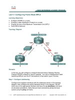
Another change that may be required is in the Route Reflector placement or configuration. Figure 3-3
shows two of the options:
•
Option A has a RR per MAN but every PE is peered to both the RRs. This provides RR redundancy
where a loss of RR does not affect the VPNs. The RRs do not need to be peered to each other.
•
Option B has two RR per MAN. The PEs in each MAN peer with their local RRs. To be able to learn
the VPN routes from the other MAN, the RRs are peered with each other in a full mesh to provide
additional redundancy. This option creates an additional level of hierarchy that can have an impact
on convergence (more RR hops thorough which the VPN route needs to be propagated).
Option A provides the simplest implementation while option B provides better scale and partitioning
capabilities that may be required when servicing large number of PEs and VPN routes.
MAN1
E-P
MAN2
E-P
MAN2
E-P
1:1 Topology Ring-type Topology
MAN1
221608
E-P
MAN2
E-P
MAN1
E-P
MAN2
E-P
3-3
Next Generation Enterprise MPLS VPN-Based WAN Design and Implementation Guide
Chapter 3 WAN Core—MPLSoL2 Service
Platforms
Figure 3-3 Route Reflector Peering
Note
While in large networks (SP-type) it is recommended to have dedicated RRs which are placed out of the
forwarding path, in smaller enterprise networks it is possible to use an existing PE as a RR. Care should
be taken to scope the additional processing overhead on the PE.
The basic P configurations have been discussed in phase 1 of the design guide and are applicable here
as well.
For multicast, the recommendation is to use MVPN as discussed in the phase 1 guide. If the VRFs are
using anycast RP, then they should be configured in each of the sites to provide local accessibility.
QoS recommendations from phase 1 hold true here as well. The only additional capability that may be
required is the ability to shape the outgoing traffic. For example, in
Figure 3-1 P1 and P3 are connected
via GE ports, but the underlying service may only be a sub-rate GE. Thus outgoing traffic on both sides
needs to be shaped to match the sub-rate.
There could be scenarios that may require the use of Inter-AS to connect the two MPLS networks. This
could be when the two networks are part of two different administrative domains or are large enough that
a flat network is not recommended. Since we have not seen such requirements yet from enterprise
networks, this is not discussed here but future versions may be updated to include it if required.
MAN1
Option A
Option B
RR1
PE2
PE1
MAN2
RR2
PE4
PE3
MAN1
RR3
RR1
PE2
PE1
MAN2
RR4
RR2
PE4
PE3
221609