Tài liệu Data Center: Securing Server Farms ppt
Bạn đang xem bản rút gọn của tài liệu. Xem và tải ngay bản đầy đủ của tài liệu tại đây (2.08 MB, 128 trang )
Corporate Headquarters
Cisco Systems, Inc.
170 West Tasman Drive
San Jose, CA 95134-1706
USA
Tel: 408 526-4000
800 553-NETS (6387)
Fax: 408 526-4100
Data Center: Securing Server Farms
March, 2003
THE SPECIFICATIONS AND INFORMATION REGARDING THE PRODUCTS IN THIS MANUAL ARE SUBJECT TO CHANGE WITHOUT NOTICE. ALL
STATEMENTS, INFORMATION, AND RECOMMENDATIONS IN THIS MANUAL ARE BELIEVED TO BE ACCURATE BUT ARE PRESENTED WITHOUT
WARRANTY OF ANY KIND, EXPRESS OR IMPLIED. USERS MUST TAKE FULL RESPONSIBILITY FOR THEIR APPLICATION OF ANY PRODUCTS.
THE SOFTWARE LICENSE AND LIMITED WARRANTY FOR THE ACCOMPANYING PRODUCT ARE SET FORTH IN THE INFORMATION PACKET THAT
SHIPPED WITH THE PRODUCT AND ARE INCORPORATED HEREIN BY THIS REFERENCE. IF YOU ARE UNABLE TO LOCATE THE SOFTWARE LICENSE
OR LIMITED WARRANTY, CONTACT YOUR CISCO REPRESENTATIVE FOR A COPY.
The Cisco implementation of TCP header compression is an adaptation of a program developed by the University of California, Berkeley (UCB) as part of UCB’s public
domain version of the UNIX operating system. All rights reserved. Copyright © 1981, Regents of the University of California.
NOTWITHSTANDING ANY OTHER WARRANTY HEREIN, ALL DOCUMENT FILES AND SOFTWARE OF THESE SUPPLIERS ARE PROVIDED “AS IS” WITH
ALL FAULTS. CISCO AND THE ABOVE-NAMED SUPPLIERS DISCLAIM ALL WARRANTIES, EXPRESSED OR IMPLIED, INCLUDING, WITHOUT
LIMITATION, THOSE OF MERCHANTABILITY, FITNESS FOR A PARTICULAR PURPOSE AND NONINFRINGEMENT OR ARISING FROM A COURSE OF
DEALING, USAGE, OR TRADE PRACTICE.
IN NO EVENT SHALL CISCO OR ITS SUPPLIERS BE LIABLE FOR ANY INDIRECT, SPECIAL, CONSEQUENTIAL, OR INCIDENTAL DAMAGES, INCLUDING,
WITHOUT LIMITATION, LOST PROFITS OR LOSS OR DAMAGE TO DATA ARISING OUT OF THE USE OR INABILITY TO USE THIS MANUAL, EVEN IF CISCO
OR ITS SUPPLIERS HAVE BEEN ADVISED OF THE POSSIBILITY OF SUCH DAMAGES.
Data Center: Securing Server Farms
Copyright © 2004 Cisco Systems, Inc. All rights reserved.
CCIP, CCSP, the Cisco Arrow logo, the Cisco Powered Network mark, Cisco Unity, Follow Me Browsing, FormShare, and StackWise are trademarks of Cisco Systems, Inc.;
Changing the Way We Work, Live, Play, and Learn, and iQuick Study are service marks of Cisco Systems, Inc.; and Aironet, ASIST, BPX, Catalyst, CCDA, CCDP, CCIE, CCNA,
CCNP, Cisco, the Cisco Certified Internetwork Expert logo, Cisco IOS, the Cisco IOS logo, Cisco Press, Cisco Systems, Cisco Systems Capital, the Cisco Systems logo,
Empowering the Internet Generation, Enterprise/Solver, EtherChannel, EtherSwitch, Fast Step, GigaStack, Internet Quotient, IOS, IP/TV, iQ Expertise, the iQ logo, iQ Net
Readiness Scorecard, LightStream, MGX, MICA, the Networkers logo, Networking Academy, Network Registrar, Packet, PIX, Post-Routing, Pre-Routing, RateMUX, Registrar,
ScriptShare, SlideCast, SMARTnet, StrataView Plus, Stratm, SwitchProbe, TeleRouter, The Fastest Way to Increase Your Internet Quotient, TransPath, and VCO are registered
trademarks of Cisco Systems, Inc. and/or its affiliates in the U.S. and certain other countries.
All other trademarks mentioned in this document or Web site are the property of their respective owners. The use of the word partner does not imply a partnership relationship
between Cisco and any other company. (0304R)
iii
Data Center: Securing Server Farms
956638
CONTENTS
Preface
i
Document Organization
i
Document Conventions
ii
CHAPTER
1
Securing Intranet Server Farms: Overview
1-1
Data Center Security
1-1
The Need for Intranet Security
1-2
Security Technologies
1-3
Data Center Security Topologies
1-3
Deploying Layer 2 Security in Server Farms
1-3
Deploying Private VLANs in the Data Center
1-4
Security Considerations in the Intranet Data Center
1-5
Deploying Network-Based Intrusion Detection
1-6
Deploying Host-Based Intrusion Detection
1-7
Data Center Networking Architecture
1-8
Network Infrastructure
1-9
Cisco Storage Networking
1-9
Application Optimization
1-10
Business Continuance Networking
1-10
CHAPTER
2
Data Center Security Topologies
2-1
Topologies
2-1
Packet Filtering: Aggregation Layer
2-3
ACLs
2-3
Appliance Firewalls
2-4
Integrated Firewalls
2-6
Packet Filtering: Access Layer
2-7
Security for Multi-Tier Server Farms
2-8
Intrusion Detection Sensors
2-10
Network IDS: Access Layer
2-11
Host IDS
2-12
CHAPTER
3
Deploying Layer 2 Security in Server Farms
3-1
Overview
3-1
Contents
iv
Data Center: Securing Server Farms
956638
Design Details
3-2
Problem Description-MAC Flooding
3-2
Solutions
3-3
Problem Description-ARP Spoofing
3-5
Solutions
3-6
Problem Description-PVLAN Vulnerabilities
3-9
Solution
3-10
Problem Description-VLAN Hopping
3-11
Solutions
3-12
Problem Description - Spanning Tree Vulnerabilities
3-13
Solutions
3-14
CHAPTER
4
Deploying Private VLANS in the Data Center
4-1
PVLAN Overview
4-1
PVLANs in the Data Center
4-1
Private VLANs and Content Switching
4-3
CSS Deployments
4-4
Solutions
4-7
CSM Deployments
4-10
Solution
4-11
CHAPTER
5
Security Considerations for the Intranet Data Center
5-1
Intranet Data Center Overview
5-1
Distributed Intranet Data Centers
5-4
Route Health Injection
5-6
Integrating Security
5-7
Unauthorized Access
5-8
Denial of Service Attacks
5-8
Network Reconnaissance/Viruses/Worms
5-9
IP Spoofing
5-9
Layer 2 Attack Mitigation
5-9
Solution Design Details
5-10
FWSM Logical Placement
5-12
Benefits
5-12
Aggregation Switch Traffic Flow
5-13
Configuration Details
5-14
Redundancy and Failover
5-18
FWSM Failure Scenario
5-21
Caveats
5-22
Contents
v
Data Center: Securing Server Farms
956638
Summary
5-23
CHAPTER
6
Deploying Network-Based Intrusion Detection
6-1
Overview
6-1
The Need for Intrusion Detection Systems
6-2
Solution Topology
6-2
Cisco IDS
6-4
Methods of Network Attack
6-5
Types of Attacks
6-5
Buffer Overflows
6-5
Worms
6-6
Trojans
6-6
CGI-Scripts
6-6
Protocol Specific Attacks
6-7
Traffic Flooding
6-7
IDS Evasion Techniques
6-7
Fragmentation
6-7
Flooding
6-8
Obfuscation
6-8
Encryption
6-9
Asymmetric Routing
6-9
Cisco IDS Attack Mitigation Techniques
6-9
Signature Analysis
6-9
Simple Pattern Matching
6-10
Session-Aware Pattern Matching
6-10
Context-Based Signatures
6-10
Protocol Decode-Based
6-10
Heuristic Analysis
6-11
Traffic Anomaly Analysis
6-11
IDS Software Configuration
6-12
Network Sensor
6-12
Traffic Capture
6-13
SPAN (Switched Port Analyzer)
6-13
VACL (VLAN Access Control Lists)
6-14
RSPAN (Remote Switched Port Analyzer) with VACL
6-15
MLS IP IDS
6-16
Management
6-16
IEV
6-17
Enterprise Class Solutions
6-18
Contents
vi
Data Center: Securing Server Farms
956638
VMS
6-18
CTR
6-20
Tuning Sensors
6-21
Cisco Product Matrix
6-22
Conclusion
6-23
CHAPTER
7
Deploying Host-Based Intrusion Detection
7-1
Overview
7-1
Benefits of Endpoint Security in the Enterprise Data Center
7-2
Solution Topology
7-3
Required Components
7-4
Server Agent for Windows
7-4
Server Agent for Solaris
7-4
Desktop Agent
7-4
CiscoWorks VMS with Management Center for Cisco Security Agents
7-5
Design Details
7-5
Design Goals
7-5
Design Recommendation
7-6
Manageability
7-7
Implementation Details
7-8
Basic Implementation Steps
7-8
Infrastructure Description
7-9
High Availability
7-11
Scalability and Performance
7-12
Limitations and Restrictions
7-13
Conclusion
7-13
Additional References
7-13
I
NDEX
i
Data Center: Securing Server Farms
956638
Preface
This Solution Reference Network Design (SRND) provides design and implementation
recommendations fo r deploying security services in the data center. This document discusses security
topologies that include both appliance and integrated devices.
This publication provides solution guidelines for enterprises implementing Data Centers with Cisco
devices. The intended audiences for this design guide include network architects, network managers, and
others concerned with the implementation of secure Data Center solutions, including:
•
Cisco sales and support engineers
•
Cisco partners
•
Cisco customers
Document Organization
This document contains the following chapters
Chapter or Appendix Description
Chapter 1, “Securing Intranet Server Farms:
Overview”
Provides an overview of the data center with special
emphasis on security in the data center.
Chapter 2, “Data Center Security
Topologies”
Provides an overview of security topologies.
Chapter 3, “Deploying Layer 2 Security in
Server Farms”
Provides design recommendations for deploying Layer
2 security in the server farm.
Chapter 4, “Deploying Private VLANS in the
Data Center”
Provides design recommendations for deploying Private
VLANs in the data center.
Chapter 5, “Security Considerations for the
Intranet Data Center”
Provides design recommendations for implementing
security for intranet server farms.
Chapter 6, “Deploying Network-Based
Intrusion Detection”
Describes the benefits of deploying network intrusion
detection in the data center and addresses mitigation
techniques, deployment models ,and the management of
the infrastructure
Chapter 7, “Deploying Host-Based Intrusion
Detection”
Describes the need for employing host-based intrusion
prevention in the data center and addresses the design,
deployment, and management of this infrastructure.
ii
Data Center: Securing Server Farms
956638
Preface
Document Conventions
Document Conventions
This guide uses the following conventions to convey instructions and information:
Convention Description
boldface font Commands and keywords.
italic font Variables for which you supply values.
[ ] Keywords or arguments that appear within square brackets are optional.
{x | y | z} A choice of required keywords appears in braces separated by vertical bars. You must select one.
screen font
Examples of information displayed on the screen.
boldface screen
font
Examples of information you must enter.
< > Nonprinting characters, for example passwords, appear in angle brackets.
[ ] Default responses to system prompts appear in square brackets.
CHAPTER
1-1
Data Center: Securing Server Farms
956638
1
Securing Intranet Server Farms: Overview
1-1
This chapter describes the importance of securing intranet server farms and introduces the different
topics described in the other chapters in the Security Intranet Server Farms SRND. It includes the
following sections:
•
Data Center Security Topologies, page 1-3
•
Deploying Layer 2 Security in Server Farms, page 1-3
•
Deploying Private VLANs in the Data Center, page 1-4
•
Security Considerations in the Intranet Data Center, page 1-5
•
Deploying Network-Based Intrusion Detection, page 1-6
•
Deploying Host-Based Intrusion Detection, page 1-7
•
Data Center Networking Architecture, page 1-8
Data Center Security
Data center security is based on an effective security policy that accurately defines access and connection
requirements within your data center. Once you have a good security policy, you can use many
state-of-the-art Cisco technologies and products to protect your data center resources from internal and
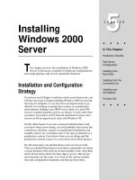
external threats and to ensure data privacy and integrity. Cisco delivers a powerful set of network security
technologies, shown in Figure 1-1, that can be deployed as standalone appliances or as modules for the
Cisco Catalyst 6500 Series. These solutions include the following categories of products and
technologies:
•
Access controls
•
Firewalls
•
Extranet VPN termination
•
Network and host-based intrusion detection and prevention systems (network and host IDS)
To understand how these technologies are integrated into the other solution areas within the Data Center
Networking Architecture, refer to the section “Data Center Networking Architecture” section on page
1-9, or see the following website:
/>Alternatively, at www.cisco.com, just enter “go/datacenter.”
1-2
Data Center: Securing Server Farms
956638
Chapter 1 Securing Intranet Server Farms: Overview
Figure 1-1 Data Center Security and Data Center Networking
The Need for Intranet Security
In addition to protecting the perimeter of the data center against external threats, you must also protect
the boundaries between functional and administrative regions within the data center. Too often, security
within the intranet data center is inadequate, even though the data center hosts vital applications and
systems related to payroll, HR, manufacturing, marketing, and R&D. Unfortunately, robust security is
often only deployed at the Internet edge to defend against external threats.
In several recent third-party network security surveys, IT managers stated that 40-60% of the attacks and
security breaches affecting their networks came from users and devices inside the network. They
estimated the loss of confidential and proprietary information from these internal attacks to have cost
their organizations an average of six million dollars per year. Such internal threats can originate from
many sources:
•
Devices compromised by outside attackers
•
Outside attackers who have compromised upstream security devices
•
Disgruntled current and former employees
•
Accidental employee actions
To protect your vital data center resources from internal threats, you can apply many of the same
technologies and strategies that work so well in defending the Internet edge. However, the security
policies that you develop for your intranet will be different, and the topologies and configuration
required to support those policies may also differ.
When designing topologies that integrate firewall and IDS devices into the data center network, you can
either use standalone appliances or service modules integrated into the Catalyst 6500 chassis. You can
integrate appliance-based products with a variety of platforms, while Catalyst 6500-based service
modules help improve performance and reduce administrative overhead through collapsed network
topologies.
104026
Storage
Network
NAS
RAID
Tape
Cisco
MDS
9500
IP Network Infrastructure
Layer 2/3
Multi-Tier
Applications
Web Servers
Application Servers
DB Servers
Main Frame
M
IP Communications
Operations
FC SAN
Application
Optimization
SSL
Content
Switch
Cache
IDS
Firewall
Security
1-3
Data Center: Securing Server Farms
956638
Chapter 1 Securing Intranet Server Farms: Overview
Data Center Security Topologies
Security Technologies
Because different types of data are kept at different tiers within the data center architecture, it is
important to deploy security between tiers so that each tier has the appropriate protection mechanisms
to guard against the most likely risks. A layered security architecture provides a scalable, modular
approach for deploying security between the multiple data center tiers. The security services most often
deployed in the data center to defend against different threats include the following:
•
ACLs—ACLs prevent unwanted access to infrastructure devices and, to a lesser extent, protect
server farm services. ACLs come in different types, including router ACLs (RACLs), VLAN ACLs
(VACLs), and QoS ACLs.
•
Firewalls—Firewalls create network boundaries between more secure and less secure resources.
While the typical location for firewalls remains the Internet edge and the edge of the data center,
they are also used in multi-tier server farm environments to increase security between the different
tiers.
•
Network and Host IDS—Network IDS proactively detects and responds to intrusion or other unusual
network activity. Host IDS enables real-time analysis and reaction to hacking attempts on specific
applications or Web servers. Host IDS is able to identify an attack and prevent access to server
resources before unauthorized transactions occur.
•
AAA—AAA provides another layer of security by preventing unauthorized user access and by
controlling user access to the network and network devices using a predefined profile. Transactions
of all authorized and authenticated users are logged for accounting purposes, for billing, or for
analysis.
Data Center Security Topologies
Traditionally, the security of the Intranet data center has not received adequate attention. However, it is
necessary to provide security to protect the data center from internally initiated attacks. In the data center
topology recommended by Cisco, the intranet data center aggregation switches are directly connected to
the campus core switches. The goal of a good security design should be to create security perimeters and
domains for both the network devices and applications residing in this internal data center that provide
protection similar to that given to external (Internet) facing devices and systems.
The intranet data center aggregation layer provides a key location for deploying firewall and IDS
services. In this architecture, the aggregation switches are in an active-standby (Layer 2-7)
configuration. This means that the active aggregation switch is the spanning tree root, the Hot Standby
Router Protocol (HSRP) active router, and active for content switching and other Layer 4-7 services.
Chapter 2, “Data Center Security Topologies.”focuses on how to deploy either appliance-based or
service module-based packet filtering and IDS services at the data center aggregation layer to protect
data center infrastructure devices and servers.
Deploying Layer 2 Security in Server Farms
Layer 2 attacks are often a topic of discussion for the campus environment, but they should not be
forgotten when discussing data center security. Designing and implementing a security policy to guard
against localized Layer 2 intrusion and attacks is an extremely important aspect of data center security
design. Many of the features that guard against these attacks also help to ensure that a misconfiguration
1-4
Data Center: Securing Server Farms
956638
Chapter 1 Securing Intranet Server Farms: Overview
Deploying Private VLANs in the Data Center
or a non-malicious event does not result in unnecessary downtime for the data center. Chapter 3,
“Deploying Layer 2 Security in Server Farms.” discusses some common Layer 2 attacks and the features
available within Cisco IOS to mitigate these attacks.
Deploying Private VLANs in the Data Center
In the server farm, many servers often reside in the same subnet (segment). If one server is compromised,
the possibility of others being compromised increases. Alternatively, if the server is secure and
uncompromised and an attacker is able to gain control of the switch, data traffic to and from servers can
be captured regardless of the security of the server OS and applications. Deploying private VLANs
(PVLANs) in an enterprise data center environment provides an effective means of controlling Layer 2
access to servers and devices residing within the server farm.
The Layer 2 isolation provided by PVLANs is an excellent way to supplement Layer 3 security. Servers
residing in an isolated VLAN can only communicate through the primary VLAN and are isolated at
Layer 2 from any other servers configured for the same or other isolated VLANs. Servers that are part
of a community VLAN can communicate at Layer 2 with all other servers residing in the same
community VLAN, but they can only communicate with other devices or servers through the primary
VLAN.
Figure 1-2 shows both community and isolated VLANs and their associated primary VLANs configured
at the data center access layer. In the example, each server configured in isolated VLANs 8 and 20 is
isolated at Layer 2 from each other and from all other servers in the server farm. The servers configured
in community VLAN 30 can communicate with each other but are isolated at Layer 2 from any server
not configured for community VLAN 30.
Figure 1-2 PVLANs Deployed at the Data Center Access Layer
In this environment, PVLAN traffic is carried between data center switches through 802.1q trunks. All
switches forwarding PVLAN traffic must be configured with the PVLAN information. In a basic data
center topology, PVLAN implementation is fairly simple and straightforward. However, when content
switching is added to the data center architecture. certain interoperability issues arise. Chapter 4,
“Deploying Private VLANs in the Data Center”discuss these issues and provides guidance and
recommendations for implementation.
Isolated
Community
20
30
8
Primary VLAN
Primary VLANs
30
Isolated
Community
10
1015
802.1q
802.1q
802.1q
802.1q
87356
1-5
Data Center: Securing Server Farms
956638
Chapter 1 Securing Intranet Server Farms: Overview
Security Considerations in the Intranet Data Center
Security Considerations in the Intranet Data Center
The security policies and deployments for the intranet data center act as a second layer of security
against external users and applications, while providing protection from unauthorized internal users,
internal systems, and remote users having access to the internal network. Because an enterprise server
farm can consist of multiple tiers, security services for the intranet server farms are not solely deployed
at the aggregation layer, but should also be deployed at each tier to protect each server farm layer, as
shown in Figure 1-3. Using a layered security architecture provides a scalable modular approach for
deploying security at each tier.
Figure 1-3 Security Services at Server Farm Tiers
The layered architecture makes use of IOS security features, firewalls, VACLs, network IDS, and host
IDS. You must take an end-to-end solution-based approach when deploying each of these security
services to ensure that features that are already implemented remain functional after security is
implemented.
The following summarizes some of the ways to address different security threats:
•
Unauthorized Access—To prevent unauthorized access, AAA is used to provide login
authentication, command authorization, and accounting information. For scalability and
manageability it is helpful to use a Terminal Access Controller Access Control System (TACACS)
server (Cisco Secure ACS), which maintains a central location for username and password
information.
87390
Third Tier
Second Tier
Web Tier
Database Tier
Application Tier
Aggregation tier
First Tier
Campus Core
1-6
Data Center: Securing Server Farms
956638
Chapter 1 Securing Intranet Server Farms: Overview
Deploying Network-Based Intrusion Detection
•
Denial of Service Attacks—You can use Cisco IOS quality of service (QoS) features to protect hosts
and links against some kinds of flooding and DoS attacks. If you do plan to use QoS features to
control flooding, it is important to understand how those features work, and how common DoS
attacks work.
•
Network Reconnaissance/Viruses/Worms—Third-party applications (such as nmap, dsniff, and
Ethereal) can be used to perform packet sniffing and port scanning on network devices or hosts to
quickly discover security holes. However, these tools can also be used maliciously. To guard against
network reconnaissance attempts, either firewalls and intrusion detection devices can be deployed.
•
IP Spoofing—ACLs should be deployed on ingress and egress interfaces throughout to block
address allocation for private (RFC 1918) address spaces. Unicast reverse path forwarding (RPF)
allows a router to verify that a packet entered the router on the correct ingress interface based on the
source address of the packet.
•
Layer 2 Attack Mitigation—Designing and implementing a security policy to guard against
localized Layer 2 intrusion and attacks is an extremely important aspect of data center security
design.
For details and implementation recommendations, refer to Chapter 5, “Security Considerations for the
Intranet Data Center.”
Deploying Network-Based Intrusion Detection
The deployment of network IDS is essential to a comprehensive security implementation. Network IDS
can be deployed at several points within a single network topology to form part of a multi-pronged
defense against external, Internet-based threats, and internal threats, including network
misconfiguration, misuse, or negligent practices. Packet inspectors, such as firewalls, are not enough to
protect business critical applications from external and internal threats.
Devices employed to enforce security policies must scrutinize the protocols and application data
traversing the network. Cisco network IDS products satisfy this requirement by identifying harmful
network traffic and performing the appropriate action based on the established security policy. Actions
that may be taken consist of logging, shunning or resetting traffic that is identified as detrimental to the
network.
Figure 1-4 indicates the multiple network vulnerability points that the enterprise security policy must
address across service domains. The deployment options for Cisco network IDS include the following:
•
Cisco Intrusion Detection System 4200 Security Appliance (Cisco IDS)
•
Cisco Intrusion Detection System Module for the Catalyst 6500 series of switches (Cisco IDSM and
IDSM-2)
•
Cisco Intrusion Detection System Module for the 2600/3600/3700 series of routers (NM-CIDS)
Each of these network sensors utilizes the Cisco IDS software, which ensures a secure network
environment through extensive inspection of potential threats.
Cisco IDS software is available as a standalone appliance or integrated into switches, routers and
firewalls.
Enterprise-level management and monitoring for Cisco IDS is delivered through browser-based user
interfaces. This provides a simplified and consistent user experience, while delivering powerful
analytical tools that allow for a rapid and efficient response to threats. Secure access to a command line
interface (CLI) is also supported. For further details and implementation recommendations, refer to
Chapter 6, “Deploying Network-Based Intrusion Detection.”
1-7
Data Center: Securing Server Farms
956638
Chapter 1 Securing Intranet Server Farms: Overview
Deploying Host-Based Intrusion Detection
Figure 1-4 Enterprise Data Center - Network Vulnerablity Points
Deploying Host-Based Intrusion Detection
Using Cisco Security Agent (CSA) for endpoint protection is one strategy in the comprehensive,
end-to-end security solution that Cisco recommends. Deploying CSA can provide the following benefits
to your organization:
•
Reduce losses in revenue and productivity from security-related outages
•
Increase IT productivity by reducing the burden of applying operating system patches
•
Protect proprietary or confidential company data
•
Maintain service level agreements (SLA)
104356
Internet Gateway
Internet Edge
Extranet
Data Center
Campus Core
Internet
SP1
Private
WAN
SP2
PSTN
Remote
Office
Or
Or
DMZ
Corporate
Infrastructure
Partners
WAN
Internet
Server
Farm
VPN
Intranet Data Center
1-8
Data Center: Securing Server Farms
956638
Chapter 1 Securing Intranet Server Farms: Overview
Data Center Networking Architecture
The CSA architecture allows authorized personnel to update server software or to patch operating
systems on a predetermined schedule, which avoids the cost of unforeseen downtime. The CSA does not
use utilize signature-based technology, but rather relies on host-based behavior to provide security. As a
result, signature updates are not necessary to protect against newly discovered threats. The CSA also
improves endpoint security management in the data center.
Enterprises often employ several host-based security products to protect data center endpoints. These
may include personal firewalls, antivirus scanners, and audit or integrity products to track malicious
configuration activity. All of these functions are replaced with a single CSA agent, and this reduces
deployment and management costs. In addition, the Management Center for Cisco Security Agents (CSA
MC) provides a single, centralized tool for deploying, administering, and monitoring CSA, and this
simplifies network management. The enterprise data center is a complex structure segmented into
service and security domains. The Internet, intranet, and extranet server farms each contain endpoints
that can benefit from deploying CSA.
Figure 1-5 illustrates the deployment of CSA on server endpoints in a data center server farm.
Figure 1-5 CSA Deployment in the Enterprise Data Center
CSA is installed on each endpoint as an agent kit, which contains the security policies to be enforced on
the endpoint. You can use default or customized agent kits, which are available for different desktop and
server environments. The CSA default kits provide comprehensive, predefined policies that protect
against many security violations, including port scan detection, buffer overflows, network worms, SYN
floods, and Trojan horse programs. For further details and implementation recommendations, refer to
Chapter 7, “Deploying Host-Based Intrusion Detection Systems.”
Data Center Networking Architecture
The Data Center Networking architecture includes a suite of advanced solutions in the following areas:
•
Data center IP network infrastructure
•
Storage networking
•
Application optimization
114023
Si Si
Si Si
1-9
Data Center: Securing Server Farms
956638
Chapter 1 Securing Intranet Server Farms: Overview
Data Center Networking Architecture
•
Data center security
•
Business continuance networking
As shown in Figure 1-6, data center services are related and interdependent. The storage networking and
network infrastructure services are the foundation because they provide the fundamental building blocks
used by every network service. After the infrastructure is in place, you can build server farms to support
the application environments. These environments should be protected using network security
technologies and optimized using load balancing and other application optimization technologies.
Figure 1-6 Functional Areas of the Data Center Networking Architecture
Once the data center is functioning in an efficient and secure way, you should ensure that the entire data
center does not provide a single point of failure through the use of distributed data centers, site selection,
SAN extension and other business continuance technologies.
Network Infrastructure
The Cisco intelligent switching infrastructure consolidates network components and resources by
supporting distinct application and server environments on the same physical infrastructure, while
maintaining their virtual separation for security and availability purposes. The term infrastructure refers
to the Layer 2 and Layer 3 configurations that provide network connectivity to the server farm as well
as the network devices that provide security and application-related functions. Data centers are
composed of devices that provide the following functions:
•
Network connectivity, including switches and routers
•
Network and server security, including firewalls and IDS
•
Availability and scalability of applications, including load balancers, SSL offloaders, and caches
The data center infrastructure must provide port density and Layer 2 and Layer 3 connectivity, while
supporting security services provided by access control lists (ACLs), firewalls and IDS. It must support
server farm services such as content switching, caching, SSL offloading while integrating with multi-tier
server farms, mainframes, and mainframe services (TN3270, load balancing and SSL offloading). For
detailed information about designing and building your network infrastructure, see the following website
Cisco Storage Networking
Direct-attached storage is expensive, difficult to manage, and inefficient, requiring very large amounts
of unused capacity to ensure availability. Storage-area network (SAN) and network-attached storage
(NAS) systems help consolidate storage, increase availability, simplify management, and reduce capital
and operational expenditures. Unfortunately, many traditional SANs result in multiple SAN “islands”
that lack the scalability and intelligence to deliver on the potential promised by storage networking.
Business Continuance Network
114448
Network
Infrastructure
Storage
Networking
Data Center Security
Application Optimization
1-10
Data Center: Securing Server Farms
956638
Chapter 1 Securing Intranet Server Farms: Overview
Data Center Networking Architecture
Cisco provides fully integrated, multilayer, intelligent storage networking solutions, built with products
such as the Cisco MDS 9000 Family, that scale to meet the needs of a SAN environment of any size.
Cisco’s innovative solutions combine advanced storage switching functions such as virtual SANs
(VSANs), traffic management, and diagnostics with network-hosted storage services to provide
unparalleled ease of management, scalability, and intelligence. For more information about Cisco
storage networking, see the following website:
/>Application Optimization
Application optimization is one of the key solution areas within the Data Center Networking
architecture. The objective of application optimization is to ensure high performance and high
availability for applications running in the enterprise data center. Optimization increases application
availability and scalability using intelligent, application-aware network technology. The network
technologies that help optimize application performance include the following:
•
Caching improves application response time.
•
Content switching and load balancing consolidate applications and increase application scalability
and availability.
•
Secure Sockets Layer (SSL) offloading allows servers to increase the number of SSL transactions
supported.
For more information about data center application optimization solutions, see the following website:
/>Business Continuance Networking
Business continuance is a top priority because customers expect continuous availability to organizational
products and services, regardless of circumstances. Business continuance keeps essential applications
running and protects valuable data during and after a disruption or failure. Cisco networking solutions
support a portfolio of business continuance strategies required to meet the different recovery point
objectives (RPOs) and recovery time objectives (RTOs) of enterprise applications. These networking
solutions include site selection between distributed data centers, storage area network (SAN) extension
for mirroring mission-critical session traffic and data, and cost-effective WAN solutions for replication
of data to offsite backup and storage locations.
The goal of disaster recovery and business continuance is guaranteed accessibility to data anywhere and
at any time. In the event of a catastrophe, meeting this objective is impossible with a single data center,
because it provides a single point of failure. With a single data center in a disaster scenario, the business
comes to a standstill until it is rebuilt and the applications and data are restored. Using distributed data
centers with Cisco site selection solutions overcome this single point of failure, while providing
additional benefits, such as application scalability, high availability, and load distribution.
SAN extension increases the geographic distance allowed for SAN storage operations, in particular for
data replication and copy operations. By replicating or copying data to an alternate site, an enterprise
can protect its data in the event of disaster at the primary site. For more information about site selection,
SAN extension, and other business continuance solutions, see the following website:
/>CHAPTER
2-1
Data Center: Securing Server Farms
956638
2
Data Center Security Topologies
The Intranet data center has traditionally been an area where security deployments have been thinly
implemented. Based on client surveys, growing security threats, and the increasing need to protect
proprietary information; it is necessary to provide security to protect the data center from internally
initiated attacks, whether malicious in nature or not. The security options discussed in this include
packet filtering and intrusion detection for network devices, servers, and applications. The goal of this
is to provide an overview and understanding of the security options available for the intranet server farm
and provide topologies that and recommendations for each of these options.
Topologies
Figure 2-1 provides an overview of a large scale enterprise network. Figure 2-1also shows the location
of the intranet data center in the network. In this topology, the intranet data center aggregation switches
are directly connected to the campus core switches. There are no firewalls or IDS devices deployed
between the data center switches and the campus core. The goal is to create security perimeters and
domains for both the network devices and applications residing in this internal data center similar to the
protection given to external (Internet) facing devices and systems.
2-2
Data Center: Securing Server Farms
956638
Chapter 2 Data Center Security Topologies
Topologies
Figure 2-1 Enterprise Network and Intranet Data Center
The intranet data center aggregation layer provides a key location for deploying firewall and IDS
services, along with a variety of other services including: content switching, SSL offloading, and VPN
termination. In this architecture, the aggregation switches are in an active-standby (Layer 2-7)
configuration. This means that the active aggregation switch is the spanning tree root, the Hot Standby
Router Protocol (HSRP) active router, and active for content switching and other Layer 4-7 services.
This focuses on deploying both appliance and integrated packet filtering and IDS services at the data
center aggregation layer to protect both data center infrastructure devices and servers. Additionally, this
also discusses supplemental security features that you can deploy at the data center access layer.
87352
Internet Gateway
Internet Edge
Extranet
Data Center
Campus Core
Internet
SP1
Private
WAN
SP2
PSTN
Remote
Office
Or
Or
DMZ
Corporate
Infrastructure
Partners
WAN
Internet
Server
Farm
VPN
Intranet Data Center
2-3
Data Center: Securing Server Farms
956638
Chapter 2 Data Center Security Topologies
Topologies
Packet Filtering: Aggregation Layer
Packet filtering provides a means for blocking unwanted externally sourced or internally sourced
network and application traffic. Packet filter services deployed at the intranet data center aggregation
layer consists of ACLs, appliance-based firewalls, and integrated blade-based firewall modules. This
section provides overviews of the three options. Figure 2-2 shows the location of the data center
aggregation layer.
Figure 2-2 Intranet Data Center Aggregation Layer
ACLs
ACL deployment in the data center is most beneficial for limiting access to and from devices (for
example, subnet segregation) through basic Layer 3 and Layer 4 packet filtering. ACLs can be set to filter
by port, but in most cases are not capable of providing upper-layer application protection. This is
partially due to ACLs lack of support for stateful packet inspection, which is a key differentiator between
ACLs and firewalls. Stateful packet inspection allows firewalls to perform packet by packet inspection
on connection oriented requests, denying incomplete or malformed requests.
87375
Front-end Layer
Database Layer
Application Layer
Data Center
Aggregation Layer
Campus Core
2-4
Data Center: Securing Server Farms
956638
Chapter 2 Data Center Security Topologies
Topologies
Appliance Firewalls
In typical designs incorporating an appliance firewall, the firewalls are deployed inline between the data
center aggregation layer and the core switches. This inline topology is sometimes deployed for
Internet-facing data center designs, but is not necessarily optimal for the intranet data center for several
reasons. If the firewalls are deployed inline as show in Figure 2-3, routing between the campus core and
data center is limited to static routing.
Figure 2-3 Appliance Firewall Deployment
This static routing requirement introduces redundancy issues, and also places limitations on the amount
of deployable features available. With static routing deployed, any loss of upstream routes on the outside
of the firewall is undetectable. If the upstream device or link fails, traffic is simply dropped by the
firewall and the data center aggregation switch is completely unaware.
Note
Beginning with PIX software release 6.3, OSPF support was added, thereby eliminating the static routing
limitation.
For redundancy, the active and standby firewalls send and receive hello packets on the outside and inside
interfaces respectively. On the inside interfaces, the hello packets are exchanged via the Layer 2
etherchannel configured between the data center aggregation switches. Because the outside interfaces
must also exchange hello packets, a Layer 2 connection must be configured between the campus core
switches. This outside Layer 2 connection configuration is not recommended because it brings Layer 2
into the core of the network and creates the possibility of a Layer 2 loop.
Campus Core
87370
2-5
Data Center: Securing Server Farms
956638
Chapter 2 Data Center Security Topologies
Topologies
For companies interested in deploying disaster recovery or business continuance, the Content Switching
Module (CSM) route health injection (RHI) feature plays an important role for the internal networks.
This feature allows the CSM to place a host route for the virtual IP address (VIP) in the multi-layer
switch feature card (MSFC), which is then propagated through out the network via the interior routing
protocol. Without dynamic routing protocol support on the firewall, this route cannot be propagated from
the data center switches to the campus core. If a static route is created as an alternative, traffic can be
black- holed because the route does not disappear when the VIP becomes unavailable.
As an alternative to deploying firewalls in front of the aggregation switches, you can deploy these
firewalls on as services switches. Service switches connect to the aggregation switches through Layer 2
trunks. Instead of deploying devices that provide services like SSL offloading, content switching, and
caching at the aggregation layer switches, you can connect these devices to the services switches. Two
primary benefits of utilizing the services switches are port preservation on the aggregation switches and
IOS restrictions on the aggregation switches. Specific versions of IOS must be used to support the
desired switch modules, which may not integrate well with a strict change management system. In some
cases, it can take six months to a year of testing to change software versions on core network devices.
Moving this requirement from the data center aggregation switches to the services switches allows for
faster deployment of these modules.
Figure 2-4 Firewalls Deployed on Data Center Service Switches
When inbound traffic is received on the data center aggregation switch, a static route is used to forward
the traffic over the Layer 2 links to the services switch. Figure 2-4 shows the location and connectivity
of the services switches and their physical connection to the firewalls. The services switch has two Layer
2 trunk links, the active link connected to the Layer 2 active aggregation switch and a standby link
(blocking) to the secondary Layer 2 aggregation switch. When traffic arrives on the services switch, it
is forwarded to the outside interface of the firewall. The firewall then either blocks or forwards the traffic
out of the inside interface back to the services switch. Because the firewall has both the outside and
inside interfaces connected to the same switch, security concerns often arise. One of the primary
concerns is that “VLAN hopping” may occur. VLAN hopping is the ability of an attacker to hop VLANs,
therefore bypassing the firewall altogether. A recent series of tests performed on the Catalyst product
Campus Core
87371
2-6
Data Center: Securing Server Farms
956638
Chapter 2 Data Center Security Topologies
Topologies
line by @Stake were specifically directed at testing the vulnerability of VLANs in these switches.
@Stake found that when VLAN security configuration guidelines were properly followed, they were not
able to hop or bypass VLANs on these switches utilizing a variety of well known attacks. The URL
below provides a link to the @Stake security document.
/>4fda.pdf
Once again this design does not allow administrators to deploy RHI for the intranet data center. The fact
that the CSM resides in the services switch and shares its client side VLAN with the inside interface of
the firewall, renders the RHI feature unusable. The CSM client-side VLAN must reside on the MSFC
for the VIP host route to be placed in the routing table. For additional information on RHI, see the
additional links section at the end of this .
Integrated Firewalls
The Firewall Services Module (FWSM) is an integrated firewall for the Catalyst 6000 series switches.
The FWSM is configured similarly to a PIX firewall and therefore can be deployed to perform stateful
packet inspection for both inbound and outbound traffic, as well as server to server communications.
This module provides packet inspection at a 5 gigabit throughput rate and supports the OSPF dynamic
routing protocol. Figure 2-5 shows the intranet data center aggregation switches with a pair of FWSMs.
Figure 2-5 Data Center Aggregations Switches with FWSM
These previously mentioned features and upcoming features like firewall virtualization, make the
FWSM a key element in redesigning security for the data center. A particular use is in designing and
deploying security for the multi-tier server farm, which with the FWSM becomes much cleaner and
easier to manage. This is detailed in the “Security for Multi-Tier Server Farms” section on page 2-8 of
this .
The FWSM is deployed in the same chassis as the MSFC and can be placed either in front or behind the
MSFC as shown in Figure 2-6. Also included in the Figure 2-6 is the respective location of the CSM.
Campus Core
87372
2-7
Data Center: Securing Server Farms
956638
Chapter 2 Data Center Security Topologies
Topologies
Figure 2-6 Logical Diagram of the FWSM, MSFC, & CSM with FWSM in Front and Behind the MSFC
To prevent VLAN misconfiguration which may allow traffic to bypass the FWSM, you must pay close
attention to which VLANs are configured on the outside and inside interfaces of the FWSM. The side of
the MSFC where you place the FWSM is dependent upon the type of configuration you are trying to
achieve.
Note
If you are deploying the RHI feature of the CSM, the FWSM should be placed on the outside of the
MSFC. This is because the CSM must place a host route for the VIP in the MSFC and therefore must
share a VLAN with the MSFC on the CSM's client-side VLAN.
When various blades like the CSM, SSLSM, VPNSM, and IDSM are placed into the same chassis,
configuration complexities arise. Software versions, VLAN configuration, and logical placement can all
play important parts in interoperability of these modules.
Packet Filtering: Access Layer
You can deploy PVLANs and IOS ACLs or VLAN ACLs (VACLs) at the access layer to limit
communication to, from, and between the servers residing in the server farm. The concept of PVLANs
is simple: PVLANs offer a means of providing Layer 2 isolation of servers from other servers residing
in the server farm. All traffic into the server farm passes through a primary VLAN. This primary VLAN
is mapped to one or more secondary VLANs. The secondary VLANs can be configured as either isolated
or community VLANs. Servers placed in isolated VLANs cannot communicate with any other servers
in the server farm. Servers placed in community VLANs can only communicate with other servers also
residing in the community VLAN.
87373
CSM CSM
MSFC
Inside
CSM CSM
MSFC
Outside
Data Center
Aggregation Switch
Data Center
Aggregation Switch