Tài liệu Networking and Desktop Protocols docx
Bạn đang xem bản rút gọn của tài liệu. Xem và tải ngay bản đầy đủ của tài liệu tại đây (671.59 KB, 42 trang )
1
○○○○○○○○○○○○○○○○○○○○○○○○○○○○○○○○○○○○○○○○○○○○○○○○
7
Networking and
Desktop Protocols
Terms you’ll need to understand:
✓ Internetwork Packet Exchange (IPX)
✓ Routing Information Protocol (RIP)
✓ NetWare Link State Protocol (NLSP)
✓ Enhanced Interior Gateway Routing Protocol (EIGRP)
✓ AppleTalk
✓ Routing Table Maintenance Protocol (RTMP)
✓ AppleTalk EIGRP
✓ DECnet
✓ OSI
✓ NetBIOS
✓ NetBEUI
✓ Windows Internet Naming Service (WINS)
✓ Dynamic Host Configuration Protocol (DHCP)
Techniques you’ll need to master:
✓ Describing how desktop protocols function
✓ Explaining the routing mechanisms for desktop protocols
✓ Managing and configuring desktop support on
Cisco routers
✓ Explaining how Windows clients browse a network
2
○○○○○○○○○○○○○○○○○○○○○○○○○○○○○○○○○○○○○○○○
Chapter 7
This chapter describes some of the more commonly used desktop protocols, with
an emphasis on topics covered in the CCIE Routing and Switching exam. The
following CCIE blueprint objectives, as defined by the Cisco Systems CCIE
program, are covered:
➤ Internetwork Packet Exchange (IPX)—NetWare Link Services Protocol
(NLSP), IPX RIP, IPX Service Advertising Protocol (SAP), IPX EIGRP,
Sequenced Packet Exchange (SPX), Network Control Protocol (NCP),
IPXWAN, IPX addressing, get nearest server (GNS) requests, Novell Direc-
tory Services (routing and mechanisms), access lists
➤ AppleTalk—Routing Table Maintenance Protocol (RTMP), AppleTalk Up-
date-Based Routing Protocol (AURP), AppleTalk EIGRP, Datagram Deliv-
ery Protocol (DDP), Zone Information Protocol (ZIP), Name Binding
Protocol (NBP), addressing (phases 1 and 2), access lists
➤ DECnet/OSI—Addressing, access lists
➤ Windows NT—NetBIOS, browsing, domain controller (such as WINS), ac-
cess lists
As with other chapters in this book, additional information is provided for complete-
ness and in preparation for additional subjects as the CCIE program expands.
Internetwork Packet Exchange (IPX)
Novell released IPX in 1980. IPX was very popular, but it was primarily designed
for local area networks (LANs). The IPX protocol is based on service advertise-
ments, called service access point (SAP). When Cisco routers are deployed in IPX
networks, they offer increased capabilities that are not usually available. For ex-
ample, Cisco routers can forward specific IPX broadcasts that allow serverless
IPX LANs to function normally. In this chapter, we will discuss the role of Cisco
routers and operation of IPX in greater detail.
IPX servers and printers send out SAPs (which are broadcast frames), and Cisco
routers listen for the SAPs and install them into a SAP table. For example, when
a PC, running IPX attempts to connect to a server, it sends out a request called a
get nearest server (GNS) request. If there are any local servers, they respond to the
PC’s GNS request. If there are no IPX servers on the local network, the Cisco
router responds instead. The client PC then makes a direct connection request to
the local or remote server through the Cisco router.
Keep in mind that GNS requests are sent as broadcast frames, and excessive
broadcasts reduce bandwidth for end users. Later in this chapter, we’ll examine
how to manage GNS requests and SAPs.
3
○○○○○○○○○○○○○○○○○○○○○○○○○○○○○○○○○○○○○○○○
Networking and Desktop Protocols
NetWare Protocol Suite
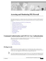
At this point, let’s take a look at the NetWare protocol suite (shown in Figure 7.1)
and how Novell’s implementation of a proprietary protocol relates to the OSI
model. As you can see in Figure 7.1, the Novell protocol suite provides applica-
tion services through NetBIOS, the NetWare shell determines whether the ap-
plication requires network services. The routing protocol used by Novell by default
is IPX RIP Let’s discuss each layer and associated protocols of the IPX model.
Application Layer (NCP)
The higher layers of IPX (layers 5 through 7) provide end users with the ability to
view files on servers. NetWare Core Protocol (NCP) is used to send and receive
files, send print jobs, and provide security. These are just some of NCP’s major
functions that are performed by the Application layer of the IPX protocol suite.
The service access point application protocol rests on top of IPX and is used to
advertise IPX services, such as file servers and printers. SAPs are sent as broad-
casts, so if you have a lot of servers and printers, you can significantly increase
your broadcast traffic. SAP services are identified in the IPX packet. For ex-
ample, the file server SAP has a type code 4, and printers have a type code 7. A
complete list of all the SAP codes is available on Novell’s Web site (search for the
keyword SAP on www.novell.com).
Application
Presentation
Session
Transport
Network
Data Link
Physical
IPX Protocol Suite
NetBIOS,
NetWare
shell
SPX
Routing Protocol,
IPX RIP, NLSP
EIGRP
IPX
Ethernet, Token Ring, FDDI,
Frame Relay, PPP, and more
OSI Model
Applications such as Network
Control Protocol (NCP) and
Service Access Point (SAP)
Figure 7.1 NetWare protocol suite.
4
○○○○○○○○○○○○○○○○○○○○○○○○○○○○○○○○○○○○○○○○
Chapter 7
Transport Layer (SPX)
The Transport layer uses the Sequenced Packet Exchange (SPX) protocol in the IPX
model. SPX provides reliable services and is connection-orientated. SPX is simi-
lar to TCP because of its ability to provide reliable connection-oriented services.
Network Layer (IPX)
The IPX Network layer provides each device with a unique network layer address
used to reach local and remote networks. IPX is connectionless. Like any routable
protocol, there must be some form of addressing. IPX addressing is unique in that
it provides for almost three times as many possible addresses as IP addressing.
An IPX address is made up of 80 bits. The first 32 bits identify the network, and
the next 48 bits are taken from the MAC address. Together, these create an IPX
address. Having all these SAPs and addresses is a benefit of IPX, however, the
next question is how does IPX route all this across the wide area network (WAN)?
To populate the IPX routing table so that routers can route IPX traffic across the
WAN, Cisco routers can use the following protocols:
➤ IPX RIP—IPX Routing Information Protocol
➤ IPX NLSP—IPX NetWare Link State Protocols
➤ IPX EIGRP—IPX Enhanced Interior Gateway Routing Protocol
NLSP is the latest implementation used to address the concerns of IPX RIP,
such as poor convergence times and hop count limits. IPX RIP supports a maxi-
mum hop count of only 15 hops, whereas IPX NLSP supports up to 127 hops.
Therefore, IPX NLSP is more scalable because the increased hop count allows
for a greater network diameter. NLSP is a link-state protocol, which means an
administrator can take advantage of all the qualities of link-state protocols as
opposed to distance-vector protocols. These qualities include faster convergence
after a network change and NLSP’s support for hierarchical network design, which
allows for networking devices to be grouped into areas and domains. There is no
need to use an Address Resolution Protocol (ARP), because the node address is
taken from the unique MAC address.
Note: The node portion of an IPX address (the last 48 bits) on a serial interface is
taken from a LAN interface, because serial interfaces do not have a MAC address.
This portion of the IPX address is taken from the first active Ethernet, Token Ring,
and then FDDI interfaces.
Data Link and Physical Layer
The Data Link and Physical layers are designed to provide physical connectivity
at an electrical level, that is the Physical layer, and they provide a reliable transit
of data across the Physical layer, that is the Data Link layer. IPX can run over
5
○○○○○○○○○○○○○○○○○○○○○○○○○○○○○○○○○○○○○○○○
Networking and Desktop Protocols
many LAN technologies, such as Ethernet and Token Ring. Further, IPX can run
over wide area networks, such as Frame Relay and Point-to-Point Protocol (PPP).
Let’s now look at how IPX is routed and configured on a Cisco router using the
three available options—IPX RIP, IPX NLSP, and IPX EIGRP.
Routing Information Protocol (RIP)
The Routing Information Protocol designed for IPX is a distance-vector protocol
that uses hop counts and ticks as the metric. Remember, a tick is a measure of delay
on an interface. IPX RIP will load balance if the hops and tick count are the same.
Let’s examine the configuration tasks on a Cisco router and the available show
commands used to monitor and verify proper operation of IPX. By default, Cisco
IOS runs IPX RIP unless configured otherwise. To enable IPX RIP routing, you
simply type the following command in global mode:
ipx routing
Like IP, you then configure network addressing on the interface that will run
IPX. This is completed with the following IOS command:
ipx network <network number> encapsulation <encapsulation type>
IPX RIP supports a number of encapsulation types. Table 7.1 shows the options
available on Cisco routers.
If no encapsulation is entered when you configure a Cisco router interface for
IPX, novell-ether for Ethernet and sap for Token Ring are the encapsulation
types set by default.
The main features of IPX RIP are that it’s a distance-vector protocol,
and the metric is based on ticks and hop counts. The maximum hop
count is 15. IPX RIP periodically sends out updates every 60 seconds.
Do not confuse this interval with the IP RIP update interval, which is
30 seconds.
Table 7.1 Cisco encapsulation options.
Media Cisco Name Novell Name
Ethernet novell-ether Ethernet_802.3
sap Ethernet_802.2
arpa Ethernet_II
snap Ethernet_Snap
Token Ring sap Token-Ring
snap Token-Ring_Snap
6
○○○○○○○○○○○○○○○○○○○○○○○○○○○○○○○○○○○○○○○○
Chapter 7
IPX RIP Configuration Task List
Now, let’s examine the configuration of a simple IPX network using IPX RIP.
Later in this chapter, we’ll use the same network to demonstrate using NLSP
and EIGRP to route IPX.
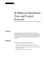
As you can see in Figure 7.2, there are two routers—R1 and R2. Both routers
have a local IPX segment. In this section, you’ll apply the default encapsulation
on all segments to novell-ether (which means that no additional configuration is
required because novell-ether is the default). Listing 7.1 displays the configura-
tion required on both routers.
Listing 7.1 IPX configuration on routers R1 and R2.
hostname R1
ipx routing 0000.0c75.d97e
interface Ethernet0
ipx network 1
interface Serial0
ipx network BAD
....
hostname R2
ipx routing 0000.0c8e.774b
interface Ethernet0
ipx network 2
interface Serial0
ipx network BAD
....
Note: In Listing 7.1, notice that the IPX network number on the serial link is the
same. If the network numbers were different, the two routers would not share IPX
routing information.
Listing 7.2 shows the IPX routing table on router R1 by using the command
show ipx route.
IPX Network 1
E0
IPX Network 2
S0
E0
S0
IPX Network BAD
R1
R2
Figure 7.2 A simple IPX network configuration task.
7
○○○○○○○○○○○○○○○○○○○○○○○○○○○○○○○○○○○○○○○○
Networking and Desktop Protocols
Listing 7.2 The show ipx route command on the R1.
R1#sh ipx route
Codes: C - Connected primary network,c-Connected secondary network
S - Static, F - Floating static, L - Local (internal),
R - RIP, E - EIGRP, N - NLSP, X - External, A - Aggregate
s - seconds, u - uses
3 Total IPX routes. Up to 1 parallel paths and 16 hops allowed.
C 1 (NOVELL-ETHER), Et0
C BAD (HDLC), Se2
R 2 [07/01] via BAD.0000.0c8e.774b, 4s, Se0
As you can see in Listing 7.2, the IPX routing table is very similar to an IP
routing table. The table displays, which IPX networks, are reachable locally (C)
and remotely (R). The network highlighted in Listing 7.2 has been discovered
dynamically using the IPX RIP (indicated by the letter R) protocol. The delay
and hop count is described in square brackets [07/01], where 07 is the delay, 01 is
the hop count. The next hop address is indicated as BAD.0000.0c8e.774b via
Serial 0 (Se0). On R1 in Listing 7.2, you can see that the remote IPX network
number 2 is reachable via the serial 0 interface. Notice also that the network was
sourced by the IPX RIP protocol, because this network is designated with the R
on the left side.
Let’s look at some useful show commands that describe the state of IPX. Listing
7.3 displays the configuration parameters on an interface by using the show ipx
interface <interface number> command.
Listing 7.3 The show ipx interface command.
R1# show ipx interface Ethernet 0
Ethernet0 is up, line protocol is up
IPX address is 1.0000.0c75.d97e, NOVELL-ETHER [up]
Delay of this IPX network, in ticks is 1 throughput 0 link delay 0
IPXWAN processing not enabled on this interface.
IPX SAP update interval is 1 minute(s)
IPX type 20 propagation packet forwarding is disabled
Incoming access list is not set
Outgoing access list is not set
IPX helper access list is not set
SAP GNS processing enabled,delay 0ms,output filter list is not set
SAP Input filter list is not set
SAP Output filter list is not set
SAP Router filter list is not set
Input filter list is not set
Output filter list is not set
Router filter list is not set
NetBIOS Input host access list is not set
NetBIOS Input bytes access list is not set
8
○○○○○○○○○○○○○○○○○○○○○○○○○○○○○○○○○○○○○○○○
Chapter 7
NetBIOS Output host access list is not set
NetBIOS Output bytes access list is not set
Updates each 60 seconds, aging multiples RIP: 3 SAP: 3
SAP interpacket delay is 55 ms, maximum size is 480 bytes
RIP interpacket delay is 55 ms, maximum size is 432 bytes
IPX accounting is disabled
IPX fast switching is configured (enabled)
RIP packets received 14415, RIP packets sent 42177
SAP packets received 0, SAP packets sent 7
The output shown in Listing 7.3 displays a wealth of information. From this
display, you can see that the encapsulation is Novell-Ether and the network number
is 1. You can also see that IPX is sending updates every 60 seconds.
Now, let’s use the show ipx server command to see which SAPs are available on
the Cisco router named R1, as shown in Listing 7.4.
Listing 7.4 The show ipx server command.
R1#show ipx server
Codes: S - Static, P - Periodic, E - EIGRP, N - NLSP,
H - Holddown, + = detail
2 Total IPX Servers
Table ordering is based on routing and server info
Type Name Net Address Port Route Hops Itf
P 4 server1 2.0000.0000.0001:0451 7/01 2 Se0
P 7 printer1 2.0000.0000.0001:0451 7/01 2 Se0
The SAP table shown in Listing 7.4 lists all the SAPs collected by router R1.
Listing 7.4 describes two services available, namely a server called server1 and a
printer named printer1. As you can see in the table, the services are reachable
through serial 0 with a hop count of 2.
Finally, here are a number of commands that you can use to troubleshoot IPX
RIP (including the commands mentioned earlier in this section):
➤ debug ipx routing—Displays information about IPX routing packets.
➤ debug ipx sap activity—Provides detailed output of SAP packets, including
displays of services in SAP packets.
➤ ipx maximum paths <number>—Defines the maximum allowed paths for load
balancing. The default is set to 1, which means there is no load balancing.
➤ show ipx interface—Describes the IPX interface configuration.
➤ show ipx route—Displays the IPX routing table.
➤ show ipx server—Displays the SAPs seen by the router.
➤ show ipx traffic—Displays IPX statistics.
9
○○○○○○○○○○○○○○○○○○○○○○○○○○○○○○○○○○○○○○○○
Networking and Desktop Protocols
NetWare Link State Protocol (NLSP)
Instead of using a distance-vector protocol to route IPX and have all the associ-
ated problems (such as convergence time and full routing updates), you can use
NLSP to carry network information so that remote networks can be visible to
each other by populating an IPX routing table. NLSP provides the ability to
propagate IPX networks without the need to send periodic updates. NLSP pro-
vides a number of advantages over IPX RIP, including:
➤ No periodic updates are sent. Updates are sent only when a change occurs.
The whole link-state database is exchanged at a predefined interval. The de-
fault is 2 hours on a Cisco router.
➤ NLSP uses a better metric than hops and ticks; instead, NLSP is based on
cost. The cost-based approach provides the administrator with the ability to
define preferred links by assigning differing costs.
➤ The maximum NLSP hop count is 127, compared to 15 with IPX RIP.
➤ Like any link-state protocol, convergence is much faster.
NetWare Link State Protocol uses hello packets to discover new IPX-speaking
routers. Further, NLSP is backward compatible with IPX RIP. Let’s take a look
at the tasks involved in configuring NLSP on a Cisco router.
Configuring NLSP
To configure NLSP on a Cisco router, you need to define an internal network
number by using the ipx internal-network network-number IOS command. The
internal network number must be unique across the network. After you assign
the number, you start NLSP by executing the ipx router nlsp command.
Note: As mentioned earlier, Cisco routers use IPX RIP to send updates by default, if
IPX routing is configured. Therefore, you must disable all IPX RIP networks that
will use NLSP; otherwise, both NLSP and IPX RIP will be used to advertise the
network. To start NLSP on an interface, use the ipx nlsp enable command.
Let’s revisit the network shown earlier in the chapter in Figure 7.2. In this sec-
tion, you’ll change the IPX routing protocol to NLSP and disable IPX RIP. List-
ings 7.5 and 7.6 display the configurations required for routers R1 and R2.
Listing 7.5 Enabling NLSP and disabling IPX RIP on router R1.
hostname R1
ipx routing 0000.0c75.d97e
ipx internal-network 10
interface Ethernet0
ip address 10.1.9.1 255.255.255.0
ipx network 1
ipx nlsp enable
10
○○○○○○○○○○○○○○○○○○○○○○○○○○○○○○○○○○○○○○○○
Chapter 7
! This command enables IPX NLSP on E0
interface Serial0
ipx network BAD
ipx nlsp enable
! Enable NLSP with the following command. The area command defines
! which networks are in NLSP. A value of 0 indicates to place all
! networks in NLSP
ipx router nlsp
area-address 0 0
!
! IPX RIP is disabled with the following command.
no ipx router rip
.....
Listing 7.6 Enabling NLSP and disabling IPX RIP on router R2.
hostname R2
ipx routing 0000.0c8e.774b
ipx internal-network 20
interface Ethernet0
ipx network 2
ipx nlsp enable
!
interface Serial0
ipx network BAD
ipx nlsp enable
! Enable NLSP with the following command. The area command defines
! which networks are in NLSP. A value of 0 indicates to place all
! network in NLSP.
ipx router nlsp
area-address 0 0
!
! IPX RIP is disabled with the following command.
no ipx router rip
....
As you can see in Listings 7.5 and 7.6, the no ipx router rip command disables
the IPX RIP process.
Note: Typically on a WAN interface, IPXWAN is used. IPXWAN is a connection
startup protocol that can be used between different router vendors. To enable
IPXWAN, you must first remove any ipx network statements and then add ipx
ipxwan.
NLSP is a link-state protocol, and you have a number of useful IOS commands
that you can use to tell you what is happening in a NLSP environment using
Cisco routers. To begin, let’s look at the IPX routing table shown in Listing 7.7.
11
○○○○○○○○○○○○○○○○○○○○○○○○○○○○○○○○○○○○○○○○
Networking and Desktop Protocols
Listing 7.7 The show ipx route command with NLSP enabled.
R1#sh ipx route
Codes: C - Connected primary network,c-Connected secondary network
S - Static, F - Floating static, L - Local (internal), W - IPXWAN
R - RIP, E - EIGRP, N - NLSP, X - External, A - Aggregate
s - seconds, u - uses
5 Total IPX routes. Up to 1 parallel paths and 16 hops allowed.
L 10 is the internal network
C 1 (NOVELL-ETHER), Et0
C BAD (HDLC), Se2
N 2 [45][05/01] via 20.0000.0000.0001, 250s, Se0
N 20 [45][06/01] via 20.0000.0000.0001, 250s, Se0
As you can see in Listing 7.7, there is a route from R2 via N (NLSP). As with any
routing table the newly acquired network is listed first followed by the ticks/
hops, and finally the next hop address.
You can also use an IOS command to view NLSP neighbor information, as dis-
played in Listing 7.8.
Listing 7.8 The show ipx nlsp neighbors command on R1.
R1#show ipx nlsp neighbors
NLSP Level-1 Neighbors: Tag Identifier = notag
System Id Interface State Holdtime Priority Circuit Id
R2 Se0 Up 44 0 01
The display in Listing 7.8 details which other NLSP routers are adjacent to R1.
In the case of R1, it is adjacent to router R2. From R1’s point-of-view once more,
the SAP table shown in Listing 7.9 tells you that NLSP discovered a server and
printer.
Listing 7.9 The show ipx route command on R1.
R1#sh ipx route
5 Total IPX routes. Up to 1 parallel paths and 16 hops allowed.
L 10 is the internal network
C 1 (NOVELL-ETHER), Et0
C BAD (HDLC), Se2
N 2 [45][05/01] via 20.0000.0000.0001, 65s, Se2
N 20 [45][06/01] via 20.0000.0000.0001, 65s, Se2
In Listing 7.9, the N designator on the left indicates NLSP advertised services.
In effect, these services will not be advertised again unless they are unavailable.
This saves bandwidth on the serial link between routers R1 and R2, thereby
saving bandwidth for end users to use to send data.
12
○○○○○○○○○○○○○○○○○○○○○○○○○○○○○○○○○○○○○○○○
Chapter 7
As with IPX RIP, NLSP has a number of commands that you can use to monitor
and troubleshoot NLSP, such as (including the commands mentioned earlier in
this section):
➤ show ipx nslp database—Displays the link-state database.
➤ show ipx nlsp neigbors—Displays NLSP speaking routers.
➤ show ipx nslp spf-log—Displays how many times the SPF algorithm has been
initiated due to a change in network availability.
➤ show ipx route—Displays any remote networks and the next hop address.
➤ show ipx server—Displays any SAPs received on an IPX interface such as
servers and printers.
Now, let’s complete our IPX routing protocols discussion by looking at the Cisco
proprietary method of advertised IPX networks—using EIGRP.
Enhanced Interior Gateway Routing Protocol (EIGRP)
You can implement Cisco’s proprietary method of routing IPX by using EIGRP.
Chapter 6 discusses EIGRP in detail in relation to IP routing. IPX EIGRP is
used to route IPX. EIGRP can also route AppleTalk, which is discussed later in
this chapter. To begin the IPX EIGRP discussion, let’s first look at the tasks
required to configure EIGRP for IPX.
Cisco IOS will automatically redistribute IPX if you are using IPX RIP or
IPX EIGRP on the same router likewise if you are using IPX RIP and
NLSP. You must manually configure redistribution between NLSP and
IPX EIGRP.
Configuring IPX EIGRP
To enable IPX EIGRP, you must apply the following command:
ipx router eigrp <AS>
Next, you apply the network that you want to advertise using IPX EIGRP. To
illustrate, let’s modify the configuration shown earlier in this chapter in Figure 7.2
to use EIGRP. Listings 7.10 and 7.11 show the new configurations for routers
R1 and R2 after enabling EIGRP.
Listing 7.10 Enabling EIGRP and disabling IPX RIP on router R1.
hostname R1
ipx routing 0000.0c75.d97e
!
13
○○○○○○○○○○○○○○○○○○○○○○○○○○○○○○○○○○○○○○○○
Networking and Desktop Protocols
interface Ethernet0
ipx network 1
!
interface Serial0
ipx network BAD
! Enable IPX EIGRP in AS 1
ipx router eigrp 1
network 1
network BAD
! Disable IPX RIP
no ipx router rip
....
Listing 7.11 Enabling EIGRP and disabling IPX RIP on router R2.
hostname R2
ipx routing 0000.0c8e.774b
!
interface Ethernet0
ipx network 2
!
interface Serial0
ipx network BAD
ipx router eigrp 1
network 2
network BAD
no ipx router rip
....
The autonomous system number used here is set to 1. The autonomous system
number identifies a group of routers under the same administrator that will share
information with each other. Therefore, routers in the same autonomous system
number, 1 in this example, will share IPX routing information.
Let’s examine the new IPX routing table after EIGRP is enabled on router R1
(shown in Listing 7.12).
Listing 7.12 The show ipx route command after enabling EIGRP.
R1#sh ipx route
Codes:C - Connected primary network,c -Connected secondary network
S - Static, F - Floating static,L-Local (internal),W-IPXWAN
R - RIP, E - EIGRP, N - NLSP, X - External, A - Aggregate
s - seconds, u - uses
3 Total IPX routes. Up to 1 parallel paths and 16 hops allowed.
C 1 (NOVELL-ETHER), Et0
C BAD (HDLC), Se0
E 2 [22798336/0] via BAD.0000.0c8e.774b, age 00:03:16,
5u, Se0
14
○○○○○○○○○○○○○○○○○○○○○○○○○○○○○○○○○○○○○○○○
Chapter 7
As you can see in Listing 7.12, IPX network 2 is reachable via IPX EIGRP (E).
The SAP table will display that the server and printer are advertised by EIGRP.
Notice that the metric displayed in Listing 7.13 is a cost value based on the
EIGRP metric calculation.
Listing 7.13 The show ipx server command after enabling EIGRP.
R1#sh ipx server
Codes: S - Static, P - Periodic, E - EIGRP, N - NLSP, H - Holddown
2 Total IPX Servers
Table ordering is based on routing and server info
Type Name Net Address Port Route Hops Itf
E 4 server1 2.0000.0000.0001:0451 22798336/00 2 Se2
E 7 printer1 2.0000.0000.0001:0451 22798336/00 2 Se2
As with IPX RIP and IPX NLSP, IPX EIGRP has a number of commands that
you can use to maintain your IPX network. Some commonly used commands are
listed here (including the commands mentioned earlier in this section):
➤ show ipx eigrp interface—Displays which interfaces are running IPX EIGRP
and if there is a peer on that interface.
➤ show ipx eigrp neighbor—Displays neighbors.
➤ show ipx eigrp topology—Details specific information about how IPX net-
works have been acquired.
➤ show ipx route—Displays the contents of the IPX routing table.
➤ show ipx server—Lists the services available as announced via SAPs.
Now that we have defined the three available methods to route IPX using Cisco
IOS commands, it’s time for us to examine how you can use access lists to man-
age traffic sent by IPX devices.
In addition to using access lists, you can send IPX traffic over an IP
backbone using a tunnel interface. This can help reduce IPX WAN-
based traffic and provide more bandwidth for user data based traffic.
IPX and Access Lists
In the first portion of this chapter, we discussed how IPX is broadcast intensive.
We also discussed ways to use Cisco’s propriety routing protocol (IPX EIGRP)
to reduce broadcasts. Another way to conserve bandwidth is to use access lists.
Access lists can help you manage IPX traffic. The access list numbers that are
available for use with IPX are:
15
○○○○○○○○○○○○○○○○○○○○○○○○○○○○○○○○○○○○○○○○
Networking and Desktop Protocols
➤ Standard IPX filters—Ranges from decimal 800 through 899
➤ Extended IPX filters—Ranges from decimal 900 through 999
➤ SAP filters—1000 through 1099; SAP filters are also used to limit GNS re-
quests
Note: Cisco IOS allows you to modify other parameters that limit the way IPX sends
and receives updates. For example, you can change the default IPX SAP update
interval (ipx sap-interval <seconds>) and IPX RIP update interval (ipx update-
time <seconds>). This is one of the ways that you can limit IPX traffic without using
ACLs or SAP filters.
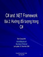
The best way to illustrate access lists is to look at an example for each filter type.
For this example, refer to Figure 7.3. Notice the figure displays the direction of
SAP updates, IPX routing updates, and GNS requests. Further, you can see in
the figure that both routers have a loopback interface (a software interface) run-
ning IPX.
Standard IPX Filters
The first step when applying a standard IPX filter is to reinstall IPX RIP as the
preferred method of routing IPX. To accomplish this, you reissue the ipx router
rip IOS command.
After enabling IPX RIP with the ipx router rip command, we need to create an
access list to stop the network from installing router R2 in router R1’s IPX routing
table. For this task, you simply use a standard access list, as shown in Listing 7.14.
Listing 7.14 IPX Access list example.
interface serial0
ipx input-network filter 800
! Applies access list to
incoming RIP updates
access-list 800 deny 2.ffff.ffff.ffff
! Stops rip updates
learned from IPX network 2
access-list 800 permit -1
!Permits all other networks
The number -1 in the access list indicates to match all networks. Next, you apply
the access list with the ipx input-network-filter 800 interface command. This
command filters incoming IPX RIP updates. You can also filter outgoing net-
work filters by using the ipx output-network-filter <800-899> command. After
executing the preceding commands, router R1 will not have network 2 in its
routing table, as shown in Listing 7.15.
16
○○○○○○○○○○○○○○○○○○○○○○○○○○○○○○○○○○○○○○○○
Chapter 7
Listing 7.15 The show ip route command after filtering network 2 as show
in Listing 7.14.
R1#sh ipx route
4 Total IPX routes. Up to 1 parallel paths and 16 hops allowed.
C 1 (NOVELL-ETHER), Et0
C 3 (UNKNOWN), Lo0
C BAD (HDLC), Se0
R 4 [07/01] via BAD.0000.0c8e.774b, 39s, Se0
Token
Ring
Sends SAP
IPX
RIP
Sends SAP
Tok0
Router
Listens to SAPs
Sends and listens to
IPX Routing updates (IPX RIP)
Send
GNS queries
IPX RIP
SAP
E0
Serial0
Printer
Printer
Client PC
Server
(Also listens for GNS queries
and replies to them)
Figure 7.3 Using access lists and GNS filters to manage IPX traffic.