Tài liệu Development of Observe By WireSystemforForkliftsUsingHapticInterface doc
Bạn đang xem bản rút gọn của tài liệu. Xem và tải ngay bản đầy đủ của tài liệu tại đây (589.77 KB, 6 trang )
International Conference on Smart Manufacturing Application
April. 9-11, 2008 in KINTEX, Gyeonggi-do, Korea
1. INTRODUCTION
Many advanced systems were developed for forklift
applications such as rear combination lights for
improved protection and reliability, traction & brake
control (TBC), system of active stability™ (SAS). In
1999, The Toyota SAS was first introduced on the
7-series. It is an electronic controlled system, which
automatically observe and controls over 3000 key
forklift functions, which senses instability and then
instantly engages the swing lock cylinder to help reduce
the risk of lateral tip-overs [1], [2]. Also, steer-by-wire
system was developed in 2002 [3]. However, to have
greater productivity and speed, forklift trucks are
designed with tall masts. The mast configurations
significantly obstruct the operator’s view to the
environment and create blind spots. As forklifts are able
to stack at higher levels, operators are less able to view
the actions occurring at the end of forks. Recently,
Trucks offer a commercial solution to the issue of tall
masts, which is called tilting cabin. The E Series model
is available with tilting cabin that rotates the driver’s
compartment allowing the operator to lay back from the
vertical which give human a much clearer view of the
lift carriage when elevated. This is a standard feature on
lift heights above 8.5 meters and optional below [4].
Unfortunately, the angle that the operator’s head has to
rotate can lead to serious risks, which are able to cause
accidents because of several loads and potential
damages over the truck. Together with this, other
technical ideas are to use vision system, which can give
the operator more visual information about the
workspace [5]. However, forklift operations are
influenced by many other factors such as lack of
illumination, limitation of workspace, driver experience,
and so on. Therefore, visibility is always critical issues
relate to forklift operation and control. Our research
motivation is to take advantage of haptic-based control
and steer-by-wire technology, which have been
implemented in many fields such as robotics, factory
automation, automobiles and so on [6], [7], [8]. The
proposed OBW system is a system that enables the
operator to concentrate on the tasks and accomplish it
faster, safer with less overturns. This device can be
integrated with the conventional steering wheel or a
steer-by-wire system as it allows drivers to perform
simultaneous steering and observe distance information
with a single steering wheel.
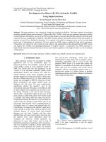
Fig. 1 Driver’s view is significantly reduced by the
loads 2, the mast configuration 1, and the rugged
overhead guard 3.
In the following papes, we initially introduce a novel
Development of an Observe-By-Wire System for Forklifts
Using Haptic Interfaces
Ba Hai Nguyen
1
and Jee-Hwan Ryu
2
1
School of Mechanical Engineering, Korea University of Technology and Education, Cheonan, Korea
(E-mail: )
2
School of Mechanical Engineering, Korea University of Technology and Education, Cheonan, Korea
(Tel : +82-41-560-1250; E-mail: )
Abstract: This paper proposes a new concept of a haptic user interface for forklifts. The haptic interface is developed
including valuable features and we named it “Observe-By-Wire” (OBW), which can give operators maximum visibility
for safe operation. Particularly, the use of an OBW can help human to overcome the problems related to the blind spots
caused by the mast configuration of forklifts. The OBW transmits distance information between forks and obstacles to
operator in term of force feedback information. It is expected to be useful in emergency cases such as: moving large
boxes, lack of illumination in warehouses. We have created an OBW system, modeled the fork and its operations.
Experiments were carried out with a group of seven subjects. The experimental results indicated that the OBW system
can improve the visibility and operating performance of forklift’s drivers. In particular, The OBW could give a
haptic-based interaction channel between the drivers and vehicles regardless to the height of masts as well as intensity
of illumination.
Keywords: Observe-by-wire, haptic interface, visibility, forklift, mast, forklift, steer-by-wire, human factors.
concept of observe-by-wire, which is a haptic-based
approach to overcome the mentioned problems. The
control strategies are shown in the section 2. The next
section, the experimental setups are described in detail.
The simulation and experiment results in section 4 have
clearly shown that the OBW system could improve the
visibility as well as forklift performances.
2. OBSERVE BY WIRE FOR FORKLIFTS
2.1 System overview
Operating a forklift is a specialized job. Drivers
control forks and its direction through the steering
wheel while they use the levels at the front panel to lift
up and down the loads. As the forks move up, operators
are less able to observe what is going on over their head.
To increase visibility, we have implemented a novel
method, which can transmit the view of forks’
environment in term of force feedback information, and
we named it as observe-by-wire system.
(a)
(b)
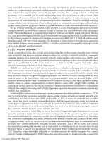
Fig. 2 The OBW system configuration, a forklift
lifts loads to the third floor for stacking or storage.
(a): forklift operation; (b): distance measurement
using four distance sensors and feedback force
implementation using a DC motor.
The essential components of an OBW system are
distance sensors associated with a haptic interface and
LabVIEW-based simulation module shown in fig. 2.
The control algorithm is applied to implement feedback
force, which is a related the measured distance from the
sensors.
Two sensors are mounted to the forks at the end of
outer sides shown in fig. 2. At these positions, the
sensor can realize the distance L between the forks to
the packages or objects along the line, which connect
two forks’ ending points. It is supposed that the
measured distances are
fr
LL , . The measured distances
sending to the controller are used in order to create
artificial force which is a function of the range from
obstacles to the forks. A haptic interface is used to give
physical interactions between human and haptic device.
It is also one in which the sensors’ signals are given to
the operator in term of the sense of touch.
2.2 Feedback force implementation:
According to previous research [9], [10], the steering
system of forklifts is developed. Moreover, driving
torque of forklift is calculated as the following equation
[11]:
.
alig
F
in
F
fr
F
sp
F
d
F +++=
(1)
Where
sp
F
is assistance force;
alig
F
,
fr
F
and
in
F
are the aligning force, friction and inertia force,
respectively. The driving torque equals a constant value
due to the forklift mechanism [11]. As operators turn on
the OBW function, basing on the distance measured
from the sensors, the force feedback torque is
defined by:
2
FFF
d
+=
. (2)
Where
2
F
is computed as following:
=
− leftturnediseelsteeringwhthewhen
r
L
G
rightturnediseelsteeringwhthewhen
f
L
G
F
,
,
2
(3)
)200,0( cmLL
fr
<<
Where:
),,,(
4321 rrrrr
LLLLMinL
=
, minimum value of
distance information measured from an array of four
sensors which are mounted on the right fork.
),,,(
4321 fffff
LLLLMinL =
, minimum value of
distance information measured from an array of four
sensors which are mounted on the left fork.
G
: is the constant gain used to change the feedback
force magnitude. The need of constant gain will be
discussed in the experimental result.
Operators can observe the operating situations of the
forks and its environment by feeling the magnitude of
the torque in the equation (3).
The negative value is added in equation (3) in order
to change force direction, which is generated by a DC
motor. The physical setup of experimental
implementation is shown in the section 3.
3. SEMI-EXPERIMENTAL SETUPS
Our test-bed is a haptic interface as shown in fig. 3
and fig. 4. This interface is used to create the feedback
force and give command known as turning angle of
forklift’s steering system. It consists of a dial as steering
wheel 1, maxon motor 2, motor driver 3, universal
motion interface UMI 7764 (4), and NI motion control
board PCI 7356 (5).
Fig. 3 The haptic interface is developed for the OBW
system
Fig. 4 The haptic interface is developed for the OBW
system
A fork system and working environment and control
algorithm are simulated in LabVIEW. The PCI board
includes 16 digital-analog converters (DAC). This
feature is useful to convert from binary value to output
voltage, which is applied on motor driver 3. This motor
diver is connected to the dial 1 (or the motor 2) as
shown in fig. 2. Computer 6 is equipped with the motion
control board 5.
The value of motor torque is calculated based on
current applied to the motor by the following equation:
IKM
M
.=
(4)
Where
M : is mecahnical torque.
I : is elctrical current.
M
K
: is torque constant
Similarly, the speed constant combines the speed
with the voltage induced in the winding. This voltage is
proportional to the speed; the following applies:
indn
UK
n
.=
(5)
Where
ind
U
is the voltage induced in the winding.
n
K
is speed constant. n is motor speed.
In addition, speed-torque line describes the
mechanical behavior of the motor at a constant voltage
U is shown in fig 5.
Fig. 5 Speed-torque line of DC motor
With reference to the mentioned equations, motor
characteristic, and 16bits DAC of motion controller, we
can enhance the output voltage range from -10 to 10
volts. The DAC value is the value sent to the DAC. The
parameter range is -32,768 to +32,767, corresponding to
the full ±10 V output range. Due to the relationship
between calculated position from simulation model and
the resolution of ADC, it is needed to do scaling before
sending value to the motor driver. In this paper, the
scaling factor is selected to be equal to 1000.
Let us now turn to describe user interface in fig. 6,
and show how the experiments are conducted by using
this simulation and the haptic interface.
First of all, the red space limiter is created to mimic
the workspace of stores. This space can be easily
changed by clicking and moving to the desired position.
The red area is referred to any package, which is
assumed that this package is placed before the driver’s
performance. Therefore, driver must stop at the position
set by the red marker. Second, the white pointer
indicates where the fork is during the experiment. Upper
and lower limit are programmed in order to ensure
safety of the electronic and mechanical systems of the
test-bed.
Fig. 6 The LabVIEW-based simulation model and
user interface for the OBW system.
Force gain is used to give adjustable feedback
torque. This is essential because of the variety of human
sensitivity. As the force gain increasing, the feedback
force is reduced. Friction and inertia term are modeled
as the conventional steering system of a forklift truck.
Finally the two graphs show the current position and the
error between desired position and current position.
4. EXPERIMENTAL RESULTS AND
DISCUSSIONS
In order to validate and investigate the possibility of
proposed control strategy and examine the
observe-by-wire system, seven subjects were asked to
participate in experiments. The task for the subject is to
move the fork (white slider) from 0 position to the
limitation where is supposed as the obstacle at the third
floor. They were trained several times to get acquainted
with the tasks. The experimental results, which are the
moving time, and errors, are automatically recorded
with two different modes: The first mode has no OWB
function. And the OWB is activated in the second mode.
Both of the two modes, users look at the set point and
turns the dial until the white slider reaches the set point.
Subjects are suggested to perform the tasks as fast as
possible. Also, they need to minimize the error as small
as they can do.
The experiment results are shown at fig. 7~ fig. 10.
The fig. 7 is randomly selected from one subject’s result.
It showed that the user could complete his or her task
three times without using the OBW system while she or
he can complete her or his task five times with the
OBW system shown in the fig. 3b. In particular, at point
(1) in the fig 7a, some vibrations were occurred due to
their attention to the set mark. However, this unwanted
result was improved with OWB system shown at (1) in
the fig. 7b. The error at point 2 of fig. 3a is 20cm. This
tumble was happened due to the lack of feedback force
because it has been reduced to 2cm when we activated
the OBW system shown at (2) in the fig. 7b.
The fig 8 shows the experimental results of seven
subjects in the same tasks. The thick line shows that the
number of completion is smaller than the thin line for all
subjects. The seventh subject even could accomplish
this taks seven times by using the OBW mode.
The fig.9 is the distance error results calculated by
the following:
N
e
Error
N
i
∑
=
1
(6)
Where,
i
e
is the error of each completion. N is the
number of completion of each subject.
The thin line clearly proves that the OBW mode
could improve the subject’s controllability. Therefore,
they achieved more accuracy of performances. The error
is rapidly decreased from 20cm to 2cm in the case of
the first subject. For the second subject, the errors of
two modes are quite similar. However, the error of the
OBW mode is still smaller.
More specially, it has been investigated with the final
experimental data that the adjustable gain is useful and
valuable. The magnitude of feedback force also effect
on the user’s performance shown in fig. 10. This figure
is the result of a randomly seleted subject with four
different gains of feedback force (FF gain). First, force
gain is set to be equal to 7. The thin black line is the
results of seven subjects. This line shows the increasing
error due to too small feedback force on the steering
wheel. Second, the thick black line indicates that errors
were minimized if the force gain was increased to 12.
This finding suggests the need of adjustable feature
mentioned in section 3. Third, the gain force is set to be
equal to 20. however, the errors of all subject are lager
than the second case. Finally, the force gain is increased
to 30. It means that system now working as a steering
system with very huge feedback force. In other word,
the drivers have to apply too much effort in order to
reach the desired position.
(a)
(b)
Fig. 7 Results of a subject, (a): without OBW mode,
(b): with OBW mode.
Fig. 8 Experimental results of seven subjects with
OBW mode and without OBW mode.
Fig. 9 Overage errors of seven subjects with OBW
mode and without OBW mode.
Fig. 10 Experimental results of a subject with four
different feedback force gains (FF Gain).
5. CONCLUSIONS
From the research that has been carried out, we can
conclude that:
The concept of obsever-by-wire is given and a
systematic study of observe-by-wire is provided in order
to give a possible method for improving the forklift’s
visibility.
The haptic interface is developed to implement the
proposed control approach. The control strategies have
been discussed, which is used in the OBW system.
In addition, the experimental results demonstrated
that the OBW system not only increases productivity
but also improves the forklift operating performance. In
particular, it could give one more interaction channel
between the drivers and vehicles regardless to the height
of masts, vehicle’s roof as well as intensity of
illumination. Therefore, the drive could also reduced
risk of damaging the load and the warehouse by
activating the OBW mode.
The discussion in section 4 indicates that the
feedback force is needed to be adjustable due to the
different sensitivity of each subject.
This paper has only been able to touch on novel
technical solution for problems of forklift’s visuality
and main features of an observe-by-wire system as well
as its possibility of implementation. In order to validate
the work we have done, a more in-depth study and
investigation on real forklift trucks is necessary.
Our future works are to develop a multifunctional
haptic device for forklift control assistance and extend
this research on other types of heavy-duty vehicles or
engineering vehicles such as excavators, cranes,
telescopic handlers.
REFERENCES
[1] TJ Larsson, T Horberry, “A Guidebook of
Industrial Traffic Management & Forklift Safety,”
Monash University, Australia, 2003
[2] D. Hrovat, “Survey of advanced suspension
developments and related optimal control
applications,” Automatica (Journal of IFAC),