Tài liệu ASM Metals HandBook P28 ppt
Bạn đang xem bản rút gọn của tài liệu. Xem và tải ngay bản đầy đủ của tài liệu tại đây (272.79 KB, 10 trang )
A few comments on what ends up as the material for a structure should also be made. First is a composition, essentially
the basic chemistry of an alloy or the specific components of a composite. Producing the structure may require a few or
many steps beyond this chemistry/components combination. Primary processing plays an important role. As examples, an
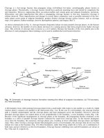
investment cast superalloy blade will have different characteristics depending on whether it is made using an equiaxed,
directionally solidified, or single-crystal process; and fiber-reinforced composites clearly have numerous wrap/lay
configurations that can influence their response. Subsequent thermal treatment for an alloy, or curing conditions for a
composite, also contribute to the end product. Many metallic alloys, far from being the uniform homogenous materials
often envisioned, are carefully orchestrated arrangements of microconstituents designed to provide specific property
balances from these in situ composites.
Effects of scale in the production of a material can have controlling effects. Examples are graphite size in gray iron,
transformation characteristics of steels or titanium alloys in heavy sections, mechanical working in forgings and
extrusions, distributions of fibers in chopped-fiber reinforced polymer parts, and phase and discontinuity distribution in
ceramics. Further considerations might include machining processes, plating, shot-peening, adhesive bonding, welding,
and a myriad of other influences that confound what initially appears to be the desired, rather straightforward association
between the material content and structure. This is coupled with the geometric requirements of shape necessary to provide
the geometry of the structure. Indeed, it is equally true that the material defines the structure and the structure defines the
material.
A small shaft simply loaded in rotating bending may behave quite like specimens tested in a similar manner. On the other
hand, a composite wing, built up from multiple parts joined by adhesives and mechanical fasteners, should not be
expected to behave in the same manner as a small simple-configuration test coupon of skin material. Attributes of the
material, coupon, or structure, along with testing conditions, contribute to the structure-sensitive mechanical behavior
identified here as fatigue properties. These have been aptly categorized by Hoeppner (Ref 8) as intrinsic and extrinsic
factors, and substantial progress has been made in understanding and controlling both. Design of the materials covers the
intrinsic characteristics (e.g., composition, grain size, cleanliness level, layup geometry, and cure cycle). Mechanical
design for a specific application addresses the extrinsic influences of the scale, geometry, stress state, loading rates,
environment, etc. Both material design and mechanical design play synergistic, substantial, and possibly determining
roles in controlling the structural response to cyclic loads.
Does this eliminate the importance of testing and property determinations? Certainly not, but it does increase awareness
of the limitations of testing and suggests that they at least be recognized and included in actual structural assessments.
The three following sections provide examples of property determinations from each of the three major groups (S-N, -N,
and da/dN). Each example demonstrates the general and/or specific aspects of the information within the context of the
design philosophy it supports. Where examples of data are offered, the reader should regard the information as indicative
only of the specific material/process/product combination involved.
Reference cited in this section
8. D.W. Hoeppner, Estimation of Component Life by Application of Fatigue Crack Growth Threshold Knowledge,
Fatigue, Creep, and Pressure Vessels for Elevated Temperature Service, MPC-17, ASME, 1981, p 1-84
Infinite-Life Criterion (S-N Curves)
Safe-life design based on the infinite-life criterion reflects the classic approach to fatigue. It was initially developed
through the 1800s and early 1900s because the industrial revolution's increasingly complex machinery produced dynamic
loads that created an increasing number of failures. The safe-life, infinite-life design philosophy was the first to address
this need.
As stated earlier, the stress-life or S-N approach is principally one of a safe-life, infinite-life regime. It is generally
categorized as a "high cycle fatigue" methodology, with most considerations based on maintaining elastic behavior in the
sample/components/assemblies examined. The "no cracks" requirement is in place, although all test results inherently
include the influence of the discontinuity population present in the samples.
This methodology is one where the influence of steel seems virtually overwhelming, despite the fact that substantial work
has been done on other alloys and materials. There are many reasons for this, including the place of steel as the
predominant metallic structural material of the century: in land transportation, in power generation, and in construction.
The "infinite-life" aspect of this approach is related to the asymptotic behavior of steels, many of which display a fatigue
limit or "endurance" limit at a high number of cycles (typically >10
6
) under benign environmental conditions. Most other
materials do not exhibit this response, instead displaying a continuously decreasing stress-life response, even at a great
number of cycles (10
6
to 10
9
), which is more correctly described by a fatigue strength at a given number of cycles. Figure
1 shows a schematic comparison of these two characteristic results. Many machine design texts cover this method to
varying degrees (Ref 9, 10, 11, 12, 13, 14).
Fig. 1 Schematic S-N representation of materials having fatigue limit behavior (asymptotically leveling off) and those
displaying a fatigue strength response (continuously decreasing characteristics)
What about the S-N data presentation? Stress is the controlling quantity in this method. The most typical formats for the
data are to plot the log number of cycles to failure (sample separation) versus either stress amplitude (S
a
), maximum stress
(S
max
), or perhaps stress range (∆S) (Ref 15). Remember that one other dynamic variable needs to be specified for the data
to make sense. Figures 2(a) and 2(b) provide plots for three constant-R value tests (R is the second dynamic variable).
Note the apparent reversal of the effect of R, although the data are identical. Clearly, while the analytical result must be
identical regardless of which graphic means is employed, the visual influence in interpretation varies with the method of
presentation.
Fig. 2 The influence of method of S-N data presentation on the perceived effect of R value. (a) Stress amplitude vs. N. (b)
Maximum stress vs. N
Many applications of this technique require estimations of initial properties and provision for approximating other effects.
Overall influences of various conditions (e.g., heat treatment, surface finish, and surface treatment) were determined
using substantial empiricism: test and report results. Consequently, much of the challenge was met by testing
coupons/components with variations in processing to establish some guidelines for the effect of each such alteration (i.e.,
see Ref 16). Thus, various correction factors were developed for a variety of conditions, including load type, stress
concentration, surface finish, and size. The influences of these intrinsic and extrinsic effects on the properties are typically
accounted for by graphics (e.g., Fig. 3), tabular presentations, or mathematical expressions. Reference 18 is an excellent
example of this approach, presented in the form of a standard.
Fig. 3 A plot of reduction factor for use in estimating the effect of surface finish on the S -N fatigue limit of steel parts.
Source: Ref 17
Mean stress influences are very important, and each design approach must consider them. According to Bannantine et al.
(Ref 13), the archetypal mean (S
m
) versus amplitude (S
a
) presentation format for displaying mean stress effects in the safe-
life, infinite-life regime was originally proposed by Haigh (Ref 19). The Haigh diagram can be a plot of real data, but it
requires an enormous amount of information for substantiation. A slightly more involved, but also more useful, means of
showing the same information incorporates the Haigh diagram with S
max
and S
min
axes to produce a constant-life diagram.
Examples of these are provided below.
For general consideration of mean stress effects, various models of the mean-amplitude response have been proposed. A
commonly encountered representation is the Goodman line, although several other models are possible (e.g., Gerber and
Soderberg). The conventional plot associated with this problem is produced using the Haigh diagram, with the Goodman
line connecting the ultimate strength on S
m
, and the fatigue limit, corrected fatigue limit, or fatigue strength on S
a
. This
line then defines the boundary of combined mean-amplitude pairs for anticipated safe-life response. The Goodman
relation is linear and can be readily adapted to a variety of manipulations.
In many cases Haigh or constant-life diagrams are simply constructs, using the Goodman representation as a means of
approximating actual response through the model of the behavior. For materials that do not have a fatigue limit, or for
finite-life estimates of materials that do, the fatigue strength at a given number of cycles can be substituted for the
intercept on the stress-amplitude axis. Examples of the Haigh and constant-life diagrams are provided in Fig. 4 and 5.
Figure 5 is of interest also because of its construction in terms of a percentage of ultimate tensile strength for the strength
ranges included.
Fig. 4 A synthetically generated Haigh diagram based on typically employed approximations for the axes intercepts and
using the Goodman line to establish the acceptable envelope for safe-life, infinite-life combinations