Tài liệu Sensor Technology Handbook P2 pptx
Bạn đang xem bản rút gọn của tài liệu. Xem và tải ngay bản đầy đủ của tài liệu tại đây (283.24 KB, 20 trang )
Sensor Fundamentals
19
Digital techniques have become increasingly popular in processing sensor outputs in
data acquisition, process control, and measurement. Generally, 8-bit microcontrollers
(8051-based, for example) have sufficient speed and processing capability for most
applications. By including the A/D conversion and the microcontroller programma-
bility on the sensor itself, a “smart sensor” can be implemented with self-contained
calibration and linearization features, among others. A smart sensor can then interface
directly to an industrial network as shown in Figure 1.2.4.
The basic building blocks of a “smart sensor” are shown in Figure 1.2.5, constructed
with multiple ICs. The Analog Devices MicroConverter™-series of products includes
on-chip high performance multiplexers, analog-to-digital converters (ADCs) and
digital-to-analog converters (DACs), coupled with Flash memory and an industry-
standard 8052 microcontroller core, as well as support circuitry and several standard
serial port configurations. These are the first integrated circuits which are truly smart
sensor data acquisition systems (high-performance data conversion circuits, micro-
controller, Flash memory) on a single chip (see Figure 1.2.6).
Figure 1.2.4: Standardization at the digital interface using smart sensors.
BRANCH
NODE
NODE
FIELD NETWORK
NODE
NODE
SMART SENSOR
SMART SENSOR
SMART SENSOR
SMART SENSOR
DEVICE NETWORK
SMART SENSORS OFFER:
� Self-Calibration
� Linearization
� Interchangeability
� Standard Digital Interfaces
Chapter 1
20
Figure 1.2.5: Basic elements in a smart sensor.
Figure 1.2.6: The even smarter sensor.
Microcontroller
High Resolution ADC
Precision Amplifier
Sensor
Pressure Sensor,
RTD,
Thermocouple
,
Strain Gage
,
etc.
Sensor
Pressure Sensor,
RTD,
Thermocouple
,
Strain Gage
,
etc.
MicroConverter™
!
21
C H A P T E R
2
Application Considerations
Jon Wilson, Technical Editor
The highest quality, most up-to-date, most accurately calibrated and most carefully
selected sensor can still give totally erroneous data if it is not correctly applied. This
section will address some of the issues that need to be considered to assure correct
application of any sensor.
The following check list is derived from a list originally assembled by Applications
Engineering at Endevco® in the late 1970s. It has been sporadically updated as ad-
ditional issues were encountered. It is generally applicable to all sensor applications,
but many of the items mentioned will not apply to any given specific application.
However, it provides a reminder of questions that need to be asked and answered dur-
ing selection and application of any sensor.
Often one of the most difficult tasks facing an instrumentation engineer is the selec-
tion of the proper measuring system. Economic realities and the pressing need for
safe, properly functioning hardware create an ever-increasing demand to obtain ac-
curate, reliable data on each and every measurement.
On the other hand, each application will have different characteristics from the next
and will probably be subjected to different environments with different data require-
ments. As test or measurement programs progress, data are usually subjected to
increasing manipulation, analysis and scrutiny. In this environment, the instrumenta-
tion engineer can no longer depend on his general-purpose measurement systems and
expect to obtain acceptable data. Indeed, he must carefully analyze every aspect of the
test to be performed, the test article, the environmental conditions, and, if available,
the analytical predictions. In most cases, this process will indicate a clear choice of
acceptable system components. In some cases, this analysis will identify unavoidable
compromises or trade-offs and alert the instrumentation engineer and his customer to
possible deficiencies in the results.
The intent of this chapter is to assist in the process of selecting an acceptable measur-
ing system. While we hope it will be an aid, we understand it cannot totally address
the wide variety of situations likely to arise.
Chapter 2
22
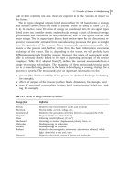
Let’s look at a few hypothetical cases where instrument selection was made with care,
but where the tests were failures.
1. A test requires that low g, low-frequency information be measured on the axle
bearings of railroad cars to assess the state of the roadbed. After considerable
evaluation of the range of conditions to be measured, a high-sensitivity, low-
resonance piezoelectric accelerometer is selected. The shocks generated when
the wheels hit the gaps between track sections saturate the amplifier, making it
impossible to gather any meaningful data.
2. A test article must be exposed to a combined environment of vibration and a
rapidly changing temperature. The engineer selects an accelerometer for its
high temperature rating without consulting the manufacturer. Thermal tran-
sient output swamps the vibration data.
3. Concern over ground loops prompts the selection of an isolated accelerometer.
The test structure is made partially from lightweight composites, and the cases
of some accelerometers are not referenced to ground. Capacitive coupling of
radiated interference to the signal line overwhelms the data.
From these examples, we hope to make the point that, for all measurement systems, it
is not adequate to consider only that which we wish to measure. In fact, every physi-
cal and electrical phenomenon that is present needs to be considered lest it overwhelm
or, perhaps worse, subtly contaminate our data. The user must remember that every
measurement system responds to its total environment.
2.1 Sensor Characteristics
The prospective user is generally forced to make a selection based on the characteris-
tics available on the product data sheet. Many performance characteristics are shown
on a typical data sheet. Many manufacturers feel that the data sheet should provide as
much information as possible. Unfortunately, this abundance of data may create some
confusion for a potential user, particularly the new user. Therefore the instrumentation
engineer must be sure he or she understands the pertinent characteristics and how they
will affect the measurement. If there is any doubt, the manufacturer should be con-
tacted for clarification.
2.2 System Characteristics
The sensor and signal conditioners must be selected to work together as a system.
Moreover, the system must be selected to perform well in the intended applications.
Overall system accuracy is usually affected most by sensor characteristics such as
environmental effects and dynamic characteristics. Amplifier characteristics such as
Application Considerations
23
nonlinearity, harmonic distortion and flatness of the frequency response curve are usu-
ally negligible when compared to sensor errors.
2.3 Instrument Selection
Selecting a sensor/signal conditioner system for highly accurate measurements
requires very skillful and careful measurement engineering. All environmental,
mechanical, and measurement conditions must be considered. Installation must be
carefully planned and carried out. The following guidelines are offered as an aid to
selecting and installing measurement systems for the best possible accuracy.
Sensor
The most important element in a measurement system is the sensor. If the data is dis-
torted or corrupted by the sensor, there is often little that can be done to correct it.
Will the sensor operate satisfactorily in the measurement environment?
Check:
Temperature Range
Maximum Shock and Vibration
Humidity
Pressure
Acoustic Level
Corrosive Gases
Magnetic and RF Fields
Nuclear Radiation
Salt Spray
Transient Temperatures
Strain in the Mounting Surface
Will the sensor characteristics provide the desired data accuracy?
Check:
Sensitivity
Frequency Response
Resonance Frequency
Minor Resonances
Internal Capacitance
Transverse Sensitivity
Amplitude Linearity and Hysteresis
Temperature Deviation
Weight and size
Internal Resistance at Maximum Temperature
Chapter 2
24
Calibration Accuracy
Strain Sensitivity
Damping at Temperature Extremes
Zero Measurand Output
Thermal Zero Shift
Thermal Transient Response
Is the proper mounting being used for this application?
Check:
Is Insulating Stud Required?
Ground Loops
Calibration Simulation
Is Adhesive Mounting Required?
Thread Size, Depth and Class
Cable
Cables and connectors are usually the weakest link in the measurement system chain.
Will the cable operate satisfactorily in the measurement environment?
Check:
Temperature Range
Humidity Conditions
Will the cable characteristics provide the desired data accuracy?
Check:
Low Noise
Size and Weight
Flexibility
Is Sealed Connection Required?
Power Supply
Will the power supply operate satisfactorily in the measurement environment?
Check:
Temperature Range
Maximum Shock and Vibration
Humidity
Pressure
Acoustic Level
Corrosive Gases
Magnetic and RF Fields
Nuclear Radiation
Salt Spray
Application Considerations
25
Is this the proper power supply for the application?
Check:
Voltage Regulation
Current Regulation
Compliance Voltage
Output Voltage Adjustable?
Output Current Adjustable?
Long Output Lines?
Need for External Sensing
Isolation
Mode Card, if Required
Will the power supply characteristics provide the desired data accuracy?
Check:
Load Regulation
Line Regulation
Temperature Stability
Time Stability
Ripple and Noise
Output Impedance
Line-Transient Response
Noise to Ground
DC Isolation
Amplifier
The amplifier must provide gain, impedance matching, output drive current, and other
signal processing.
Will the amplifier operate satisfactorily in the measurement environment?
Check:
Temperature Range
Maximum Shock and Vibration
Humidity
Pressure
Acoustic Level
Corrosive Gases
Magnetic and RF Fields
Nuclear Radiation
Salt Spray
Chapter 2
26
Is this the proper amplifier for the application?
Check:
Long Input Lines?
Need for Charge Amplifier
Need for Remote Charge Amplifier
Long Output Lines
Need for Power Amplifier
Airborne
Size, Weight, Power Limitations
Will the amplifier characteristics provide the desired data accuracy?
Check:
Gain and Gain Stability
Frequency Response
Linearity
Stability
Phase Shift
Output Current and Voltage
Residual Noise
Input Impedance
Transient Response
Overload Capability
Common Mode Rejection
Zero-Temperature Coefficient
Gain-Temperature Coefficient
2.4 Data Acquisition and Readout
Does the remainder of the system, including any additional amplifiers, filters, data
acquisition and readout devices, introduce any limitation that will tend to degrade the
sensor-amplifier characteristics?
Check: ALL of previous check items, plus Adequate Resolution.
2.5 Installation
Even the most carefully and thoughtfully selected and calibrated system can produce
bad data if carelessly or ignorantly installed.