Tài liệu Controllable Gas Springs P1 pptx
Bạn đang xem bản rút gọn của tài liệu. Xem và tải ngay bản đầy đủ của tài liệu tại đây (1.91 MB, 30 trang )
Controllable
Gas Springs
Subject to alterations
2
Overview of Gas Springs
Subject to alterations
3
Page
FIBRO – The latest technology – with a tradition of service 4 - 5
Introduction 6
Description of the main components
8
Active gas springs (KF) 2489.14. 8
Passive gas springs (KP) 2489.16. 9
Valve block 2489.00.40/41 10
Description of the functions
11
Controllable gas spring KF 11 - 12
KF + KP system without spring back 13 - 14
Heating - cooling 15
Selecting the components
17 - 19
KF order form 20
KF + KP order form
21
Dimensions and Order Numbers 23
Active gas springs (KF) 2489.14. 24 - 25
Passive gas springs (KP) 2489.16. 26
Control system 27 - 28
Compressed air connections for 6 mm hose 29 - 30
Control valves 31
Filling and emptying gas, KF 32 - 33
Filling and emptying gas, KF + KP 34 - 35
Valve block 36
Control unit 37
Gauging hoses / gauging couplings / distributor box 38 - 39
Connecting hoses / direct connection / dimensions 40 - 42
Monitoring Process Safety 43
Overheating protection 44
Monitoring air pressure 45
Mechanical control system 46
Pressure sensor 47
Pressure switch 48
Rating plate 49
Cooling 51 - 53
Gas cooler 54 - 57
Cooling unit for controllable gas springs 58
Hose and hose connectors, cooling system 59
Distributor block, cooling system 60
Connector block, cooling system 60
Quick release connector, cooling system 60
Hose and hose connector 61
Typical Applications 63
Example of application with Gas Spring system KF+KP 64 - 67
FAQs 68 - 70
Matching the stroke length in KF Gas Springs 71 - 72
Suggestion: conversion of existing systems 73
Contents
2·17243· 2001· 1 ▼
Subject to alterations
4
2·15XXX· 2000·1 ▼
FIBRO - your production partner
Hassmersheim plant
Standard Parts
Weinsberg plant
Indexing Tables
From 1962 onwards FIBRO pioneered the design and
manufacture of indexing tables and soon gained an
enviable reputation.
FIBROTAKT
®
indexing tables with face gear and ultra-high
precision indexing, together with dependable rigidity.
Drive options: pneumatic, hydraulic via rack and pinion
or electric with worm drive.
FIBROPLAN
®
NC – indexing tables with backlash
adjustment worm drive or torque motor for use in
machine tools for universal positioning and round and
multi-axis processes (simultaneous operation).
FIBROTOR
®
revolving tables and indexing tables with
positive drive cam, offering very short cycle times even
when transporting heavy loads. Mainly used in non-
machining applications. Thousands of FIBRO units are in
use world-wide as integral key components in high-
output machinery.
Today the Standard Parts Division operates from
the Hassmersheim and Weinsberg works, which
manufacture a comprehensive range of standard parts
and maintain stocks ready for immediate despatch
world-wide. The machine tool, mechanical engineering
and systems engineering product ranges have been
developed to meet the needs of customers.
They include steel die sets, guide elements, oilless guide
elements and precision components such as punches
and matrixes, special steel compression springs, gas
springs, forming materials, metal bonding agents,
moulding resins, peripheral equipment for pressing and
tool making, tool slides with cam or roller slides and
hydraulic cam systems.
FIBRO has become renowned world-wide for its
comprehensive range of products in stock and its
readiness to deliver.
FIBRO – an internationally successful company.
As a market leader in Standard Parts, Rotary Indexing
Tables and Automation, FIBRO provides products and
solutions to ensure your production keeps moving.
So what is the secret of the FIBRO success? Products
developed in-house, tailor-made for the market with
uncompromising quality.
But good products are not enough on their own.
FIBRO combines excellent products, the know-how and
service competence of an internationally focused
company, matched to the actual needs of customers -
wherever they are.
Subject to alterations
5
2·15XXX· 2000·1 ▼
Automation
FIBRO has been active in the field of automation and
robotics since 1974 and offers one of the most
comprehensive ranges in this field. A cleverly designed
modular system based on translation units, rotary units,
grippers, and guide gantries with trolleys make for easy
construction of individual machines and complete
systems, ranging from simple pick & place units right up
to multi-axis robots. These series-manufactured modules
with electric, pneumatic or hydraulic drive, guarantee
both high functional reliability and cost-effective prices.
The modular gantry systems can solve virtually any
transporting problem using linear gantries, surface
gantries and extension gantries. These systems are
being used successfully in many industries world-wide.
Applications include linking machine tools (automotive
production), tool changing in machining facilities,
palletising work pieces, unloading injection moulding
dies, PCB feeders, press linking, palletising, stacking,
loading and unloading, transporting and flexible linking,
storage and buffering of work pieces of different sizes.
Our production range consists of linear and surface
gantry systems, transport systems such as precision
roller guides, accumulating chain conveyors, pallet
accumulating conveyors and flexible decoupling
modules,shelf stacking systems and pallet mechanical
handling systems.
We can provide our customers with dependable state of
the art high performance systems from our standard
range. We take complete responsibility for the complete
project, starting with designing the solution concepts at
the design phase, right through to the final handover of
the ready-to-go system.
FIBRO is customer-focused – world-wide. A well-developed
network of sales and service points and strategic partners
ensure that help is always at hand. This ensures technical
advance, world-wide experience in applications and rapid
availability of products.
Facts and figures on FIBRO:
- founded 1958
- approximately 1,000 staff
-
approx. 100 representatives and service stations world-wide
-
branches in France, USA, Canada, India, Switzerland
and Singapore
-
ISO 9001:2000 Quality Assurance and VDA 6.4 certification
Subject to alterations
6
2·17244· 2001· 1 ▼
489.14.
Controllable Gas Springs 2489.16.
Introduction
Controllable gas springs (KF springs) are gas springs
which can be locked in their bottom position.
The timing of the return stroke can be controlled to suit
the application.
Controllable gas springs are available in 15 kN, 30 kN, 50
kN and 75 kN versions.
For best results the stroke length must always be used
to the full with a tolerance of ± 0.5 mm.
For this reason the springs are available with any stroke
length from 4 to 167 mm in 1 mm increments.
The gas spring return stroke can be controlled
electrically or pneumatically from either the tool or the
press end.
In the basic version of the gas spring (KF), it returns
about 1 mm before it is held in the bottom position. This
spring back effect can be eliminated, if required, by
connecting the KF gas spring to a passive gas spring
(KP) via a valve block. This is known as a KF + KP system.
Both variants are illustrated in this brochure.
General instructions
You can ensure system safety and reliability by supplying FIBRO with the application data and drawings of the
installation arrangements for checking.
Please note that the number of the screwed connections and the hose lengths for installation in the system must be
determined.
Assembly, commissioning, maintenance and servicing of controllable gas springs require special
knowledge and may only be carried out by FIBRO appropriately trained, specialist personnel.
You can arrange for the work to be completed by a FIBRO customer service engineer, the invoiced cost including the
assembly kits.
Just contact us to schedule the work for you.
We shall be pleased to answer any technical queries you may have, now or at any time in the future.
As controllable gas springs include parts which are specially made to specific stroke length, we
recommend that you keep reserve systems in stock to avoid the risk delay when the need arises.
Subject to alterations
7
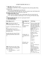
2·17245· 2001· 1 ▼
no spring back
max. press stroke
max. spring travel
0
Stroke
Gas spring
Press
time
max. Spring back 1 mm
max. press stroke
max. spring travel
0
Stroke
Gas spring
Press
Time
2489.14.
2489.16. Controllable Gas Springs
2489.13.
KF (Rückfederung max. 1 mm)
2489.14.
KF (max. spring back 1 mm)
2489.14. + 2489.16.
KF+KP system (without spring back)
KF
KP-System (ohne Rückfederung)
2489.13.
KF
2489.16.
KF
Aktiv
KP
Passiv
Ventilblock
KF
active
valve block
KP
passive
Subject to alterations
8
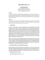
Description of the components
Active gas springs KF
2489.14.
The KF controlled Gas Spring 2489.14. can be locked in
its bottom position.
The Gas Spring consists of a cylinder (1), a guide (2), the
piston and piston rod assembly (3), return valves (6),
and internal piston rod (4) and a cartridge valve in the
bottom of the Gas Spring (5).
There is also a version with a cooling jacket (7)
(see pp 15 & 52).
There are three ports in the base of the Gas Spring: two
nitrogen (1) and (3), connected to the gas cavities in the
Gas Spring, and a compressed air port (4) for the
compressed air to operate the cartridge valve.
Port (1) is used for emptying the Gas Spring via the
passive GDF (KP), port (3) for filling it with nitrogen.
Compressed air applied at port (4) closes the cartridge
valve. In the absence of air pressure the valve opens.
2·17246·2001· 1 ▼
Controllable Gas Springs 2489.14.
2489.13.
3
2
1
4
5
6
7
4 1 3
Stickstoffanschlüsse Druckluftanschluss
2489.14.
2489.14.
2489.14.
Compressed air port
Nitrogen ports
Subject to alterations
9
Passive gas springs (KP)
2489.16.
The passive KP gas spring 2489.16 is used to prevent the KF
gas spring(s) springing back.
The KP gas spring must not be used in the
operational working area of the tool, but must
be compressed by the tool.
The passive gas spring consists of one cylinder (1), a guide (2)
and piston and piston rod (3). The piston divides the gas
spring into two gas compartments, the upper (4) and the
lower (6).
The upper compartment has four G 1/8” ports (5), the lower a
G1/8" gas filling port (7).
2489.16.
Controllable Gas Springs
2·17247·2001·1 ▼
2489.16.
2
4
3
6
7
5
1
2489.16.
Subject to alterations
10
2·17248· 2001· 1 ▼
Controllable Gas Springs 2489.00.47.01
Valve block with no facilities for
filling or emptying (2489.00.47.01)
This valve block is used for controlling the flow of gas
from the KF Gas Spring to the KP Gas Spring.
This valve block must be used with control fitting
2480.00.31.01 for filling or emptying nitrogen .
The valve block consists of a block (4), return valves (2)
and a cartridge valve (6). The block has two ports (1,3)
for connecting to the KF Gas Spring(s) and a port (5) for
connecting the passive KP spring. The compressed air
port (C) is used for controlling the cartridge valve.
Valve block 2489.00.47.01
Filling port
C
2
6 4
1 5
3
Befüllanschluss
Anschluss zur
Entleerung
Filling port
Emptying
port
Subject to alterations
11
2·17249·2001· 2 ▼
2489.14. Controllable Gas Springs
2489.16. Description of the functions
Description of the functions
Controllable gas springs
KF 2489.14.
The KF gas spring has a locking function at the
bottom position. Before the gas spring is held
completely at the bottom position there is a slight
spring back of 1 mm (or less). The complete stroke
must be used, with a tolerance of 0.5 mm.
Note:
If the full stroke length is not used
thespring back is more than 1 mm.
Fig. A, return stroke
Fig. B, Gas spring at bottom position.
1
3
2
4
5
1
4
Abb. A, Abwärtshub Abb. B, Gasdruckfeder in unterer Position Abb. C, Rückhub
1
3
2
4
5
1
4
Abb. A, Abwärtshub Abb. B, Gasdruckfeder in unterer Position Abb. C, Rückhub
Down stroke
The KF gas spring has two compartments, an upper
one (1) and a lower one (2) which are separated by
the piston of the gas return spring. The gas flow
between these two compartments is as follows:
Fig. A shows the gas spring piston down stroke.
During the down stroke the gas flows unimpeded
through the return valve of the piston (3) from the
lower (2) to the upper (1) gas compartment of the
gas spring. The cartridge valve (4) in the base of the
spring is closed.
As soon as the press and the gas spring reach the
bottom position the return valves (3) close. (Fig. B).
The gas spring is now "locked".
The pressure of the gas above and below the piston
is the same. But as the surface exposed to the gas on
the underside of the piston is larger than that on the
upper side, there is a greater force applied. On the
return stroke of the press (relief of spring) this force
is released and causes the spring to return 1 mm.
This results in a reduction of the pressure under the
piston as the gas has been allowed to expand. The
pressure in the upper compartment increases until
there is a state of equilibrium.
At this moment the gas spring stops completely.
max. Spring back 1 mm
max. press stroke
max. spring travel
0
Stroke
Gas spring
Press
Time
Subject to alterations
12
Controllable Gas Springs 2489.14.
Description of the functions 2489.16.
2·17250· 2001·1 ▼
Return stroke
The Gas Spring is released from its locked position when the
cartridge valve (4) in the Gas Spring base is opened by the
removal of pressure. (Fig. C). This causes the gas to flow
through the piston rod (5) from the upper compartment (1)
via the cartridge valve (4) back into the lower chamber (2).
The speed of the upstroke is approximately 0.2 m/s in
models 2489.14.01500. and .03000. and approximately 0.15
m/s in models 2489.14.05000. and .07500.
1
3
2
4
5
1
4
Abb. A, Abwärtshub Abb. B, Gasdruckfeder in unterer Position Abb. C, Rückhub
2
Fig. C, return stroke
Pneumatic control (controlled compressed air available from
the press)
If there is a line for controlled compressed air from the press,
this can be used directly to operate the cartridge valve.
gas spring
locked
24
0 0V (open)
24 V DC
0 bar
Min. 5 bar
0 bar
Min. 5 bar
t
2
t
10
t
t
2
t
10
t
open closed
Hub
Gas spring
Press
0
0
KF-Steuerungssystem
time
max. spring level
max. press stroke
Valve KF gas spring
Compressed air signal
A. Signal at port 4 or
pneumatic valve.
open
t
0
before UT of press
t
1
UT of the press
t
2
beginning of return stroke of gas spring
t
2
t
10
t
Electrical control
signal
KF control system
As described above, the return stroke of the Gas Spring is
controlled by the cartridge valve in the base of the Gas
Spring. The valve is closed by compressed air and opened by
the absence of pressure.
gas spring
locked
24
0 0V (open)
24 V DC
0 bar
Min. 5 bar
0 bar
Min. 5 bar
t
2
t
10
t
t
2
t
10
t
open closed
Hub
Gas spring
Press
0
0
KF-Steuerungssystem
time
max. spring level
max. press stroke
Valve KF gas spring
Compressed air signal
A. Signal at port 4 or
pneumatic valve.
open
t
0
before UT of press
t
1
UT of the press
t
2
beginning of return stroke of gas spring
t
2
t
10
t
Electrical control
signal
A constant supply of compressed air is required for both
the pneumatic and the electro-pneumatic valves. The
required minimum pressure is 4 bar.
A control valve can control up to 6
Gas Springs.
The control signals for the Gas Springs and the valves
are shown in the diagrams.
Electric control (electric control signal from the press
available)
If there is an electrical control signal available from the
press then the 2489.00.41.32 electro-pneumatic control
valve can be used to convert the electrical signal into a
pneumatic one.
gas spring
locked
24
0 0V (open)
24 V DC
0 bar
Min. 5 bar
0 bar
Min. 5 bar
t
2
t
10
t
t
2
t
10
t
open closed
Hub
Gas spring
Press
0
0
KF-Steuerungssystem
time
max. spring level
max. press stroke
Valve KF gas spring
Compressed air signal
A. Signal at port 4 or
pneumatic valve.
open
t
0
before UT of press
t
1
UT of the press
t
2
beginning of return stroke of gas spring
t
2
t
10
t
Electrical control
signal
Steuersignal
Control signal