Tài liệu 80C51 Family Architecture ppt
Bạn đang xem bản rút gọn của tài liệu. Xem và tải ngay bản đầy đủ của tài liệu tại đây (74.18 KB, 15 trang )
Philips Semiconductors
80C51 Family 80C51 family architecture
1
March 1995
80C51 ARCHITECTURE
MEMORY ORGANIZATION
All 80C51 devices have separate address spaces for program and
data memory, as shown in Figures 1 and 2. The logical separation of
program and data memory allows the data memory to be accessed
by 8-bit addresses, which can be quickly stored and manipulated by
an 8-bit CPU. Nevertheless, 16-bit data memory addresses can also
be generated through the DPTR register.
Program memory (ROM, EPROM) can only be read, not written to.
There can be up to 64k bytes of program memory. In the 80C51, the
lowest 4k bytes of program are on-chip. In the ROMless versions, all
program memory is external. The read strobe for external program
memory is the PSEN
(program store enable).
Data Memory (RAM) occupies a separate address space from
Program Memory. In the 80C51, the lowest 128 bytes of data
memory are on-chip. Up to 64k bytes of external RAM can be
addressed in the external Data Memory space. In the ROMless
version, the lowest 128 bytes are on-chip. The CPU generates read
and write signals, RD
and WR, as needed during external Data
Memory accesses.
External Program Memory and external Data Memory may be
combined if desired by applying the RD and PSEN signals to the
inputs of an AND gate and using the output of the gate as the read
strobe to the external Program/Data memory.
Program Memory
Figure 3 shows a map of the lower part of the Program Memory.
After reset, the CPU begins execution from location 0000H. As
shown in Figure 3, each interrupt is assigned a fixed location in
Program Memory. The interrupt causes the CPU to jump to that
location, where it commences execution of the service routine.
External Interrupt 0, for example, is assigned to location 0003H. If
External Interrupt 0 is going to be used, its service routine must
begin at location 0003H. If the interrupt is not going to be used, its
service location is available as general purpose Program Memory.
The interrupt service locations are spaced at 8-byte intervals: 0003H
for External Interrupt 0, 000BH for Timer 0, 0013H for External
Interrupt 1, 001BH for Timer 1, etc. If an interrupt service routine is
short enough (as is often the case in control applications), it can
reside entirely within that 8-byte interval. Longer service routines
can use a jump instruction to skip over subsequent interrupt
locations, if other interrupts are in use.
The lowest 4k bytes of Program Memory can either be in the on-chip
ROM or in an external ROM. This selection is made by strapping the
EA
(External Access) pin to either V
CC
, or V
SS
. In the 80C51, if the
EA pin is strapped to V
CC
, then the program fetches to addresses
0000H through 0FFFH are directed to the internal ROM. Program
fetches to addresses 1000H through FFFFH are directed to external
ROM.
If the EA
pin is strapped to V
SS
, then all program fetches are
directed to external ROM. The ROMless parts (8031, 80C31, etc.)
must have this pin externally strapped to V
SS
to enable them to
execute from external Program Memory.
The read strobe to external ROM, PSEN
, is used for all external
program fetches. PSEN is not activated for internal program fetches.
The hardware configuration for external program execution is shown
in Figure 4. Note that 16 I/O lines (Ports 0 and 2) are dedicated to
bus functions during external Program Memory fetches. Port 0 (P0
in Figure 4) serves as a multiplexed address/data bus. It emits the
low byte of the Program Counter (PCL) as an address, and then
goes into a float state awaiting the arrival of the code byte from the
Program Memory. During the time that the low byte of the Program
Counter is valid on Port 0, the signal ALE (Address Latch Enable)
clocks this byte into an address latch. Meanwhile, Port 2 (P2 in
Figure 4) emits the high byte of the Program Counter (PCH). Then
PSEN
strobes the EPROM and the code byte is read into the
microcontroller.
Program Memory addresses are always 16 bits wide, even though
the actual amount of Program Memory used may be less than 64k
bytes. External program execution sacrifices two of the 8-bit ports,
P0 and P2, to the function of addressing the Program Memory.
External
Interrupts
Interrupt
Control
CPU
Osc
4k
ROM
Bus
Control
128
RAM
Four I/O Ports
P0 P2 P1 P3
Address/Data
Serial
Port
Timer 1
Timer 0
Counter
Inputs
TXD RXD
SU00458
Figure 1. 80C51 Block Diagram
Philips Semiconductors
80C51 Family 80C51 family architecture
March 1995
2
EA = 0
External
EA = 1
Internal
PSEN
0000
0FFFH
FFFFH:
Program Memory
(Read Only)
Data Memory
(Read/Write)
RD WR
FFH:
00
Internal
External
FFFFH:
SU00459
Figure 2. 80C51 Memory Structure
Interrupt
Locations
Reset
0023H
001BH
0013H
000BH
0003H
0000H
8 Bytes
SU00460
Figure 3. 80C51 Program Memory
80C51
Latch
EPROM
P0
ALE
EA
P2
PSEN
OE
ADDR
SU00461
Figure 4. Executing from External Program Memory
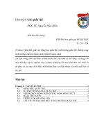
Data Memory
The right half of Figure 2 shows the internal and external Data
Memory spaces available to the 80C51 user. Figure 5 shows a
hardware configuration for accessing up to 2k bytes of external
RAM. The CPU in this case is executing from internal ROM. Port 0
serves as a multiplexed address/data bus to the RAM, and 3 lines of
Port 2 are being used to page the RAM. The CPU generates RD
and WR signals as needed during external RAM accesses. There
can be up to 64k bytes of external Data Memory. External Data
Memory addresses can be either 1 or 2 bytes wide. One-byte
addresses are often used in conjunction with one or more other I/O
lines to page the RAM, as shown in Figure 5.
Two-byte addresses can also be used, in which case the high
address byte is emitted at Port 2.
Internal Data Memory is mapped in Figure 6. The memory space is
shown divided into three blocks, which are generally referred to as
the Lower 128, the Upper 128, and SFR space.
Philips Semiconductors
80C51 Family 80C51 family architecture
March 1995
3
Internal Data Memory addresses are always one byte wide, which
implies an address space of only 256 bytes. However, the
addressing modes for internal RAM can in fact accommodate 384
bytes, using a simple trick. Direct addresses higher than 7FH
access one memory space, and indirect addresses higher than 7FH
access a different memory space. Thus Figure 6 shows the Upper
128 and SFR space occupying the same block of addresses, 80H
through FFH, although they are physically separate entities.
The Lower 128 bytes of RAM are present in all 80C51 devices as
mapped in Figure 7. The lowest 32 bytes are grouped into 4 banks
of 8 registers. Program instructions call out these registers as R0
through R7. Two bits in the Program Status Word (PSW) select
which register bank is in use. This allows more efficient use of code
space, since register instructions are shorter than instructions that
use direct addressing.
The next 16 bytes above the register banks form a block of
bit-addressable memory space. The 80C51 instruction set includes
a wide selection of single-bit instructions, and the 128 bits in this
area can be directly addressed by these instructions. The bit
addresses in this area are 00H through 7FH.
All of the bytes in the Lower 128 can be accessed by either direct or
indirect addressing. The Upper 128 (Figure 8) can only be accessed
by indirect addressing.
Figure 9 gives a brief look at the Special Function Register (SFR)
space. SFRs include the Port latches, timers, peripheral controls,
etc. These registers can only be accessed by direct addressing.
Sixteen addresses in SFR space are both byte- and bit-addressable.
The bit-addressable SFRs are those whose address ends in 0H or 8H.
80C51
with
Internal
ROM
Latch
Data
P0
ALE
EA
P2
RD
OE
ADDR
VCC
WR
WE
RAM
P3
I/O
Page
Bits
SU00462
Figure 5. Accessing External Data Memory
If the Program Memory Is Internal,
the Other Bits of P2 Are Available as I/O
Accessible
by Indirect
Addressing
Only
Accessible
by Direct
and Indirect
Addressing
Accessible
by Direct
Addressing
FFH
80H
7FH
Upper
128
Lower
128
0
Special
Function
Registers
FFH
80H
Ports,
Status and
Control Bits,
Timer,
Registers,
Stack Pointer,
Accumulator
(Etc.)
SU00463
Figure 6. Internal Data Memory
7FH
2FH
20H
18H
10H
08H
0
11
10
01
00
Bank
Select
Bits in
PSW
Bit-Addressable Space
(Bit Addresses 0-7F)
4 Banks of
8 Registers
R0-R7
1FH
17H
0FH
07H
Reset Value of
Stack Pointer
SU00464
Figure 7. Lower 128 Bytes of Internal RAM
FFH
80H
No Bit-Addressable
Spaces
SU00465
Figure 8. Upper 128 Bytes of Internal RAM
Philips Semiconductors
80C51 Family 80C51 family architecture
March 1995
4
FFH
E0H
B0H
A0H
90H
80H
ACC
Port 3
Port 2
Port 0
Port 1
Register-Mapped Ports
Addresses that end in 0H or 8H
are also
bit-addressable.
- Port Pins
- Accumulator
- PSW
(Etc.)
.
.
.
.
.
.
.
.
.
.
.
.
SU00466
Figure 9. SFR Space
CY AC F0 RS1 RS0 OV P
PSW 7
Carry flag receives carry out
from bit 7 of ALU operands
PSW 0
Parity of accumulator set
by hardware to 1 if it contains
an odd number of 1s; otherwise
it is reset to 0.
PSW 1
User-definable flag
PSW 6
Auxiliary carry flag receives carry out from bit 3
of addition operands.
PSW 5
General purpose status flag
PSW 2
Overflow flag set by
arithmetic operations
PSW 3
Register bank select bit 0
PSW 4
Register bank select bit 1
SU00467
Figure 10. PSW (Program Status Word) Register in 80C51 Devices
80C51 FAMILY INSTRUCTION SET
The 80C51 instruction set is optimized for 8-bit control applications.
It provides a variety of fast addressing modes for accessing the
internal RAM to facilitate byte operations on small data structures.
The instruction set provides extensive support for one-bit variables
as a separate data type, allowing direct bit manipulation in control
and logic systems that require Boolean processing.
Program Status Word
The Program Status Word (PSW) contains several status bits that
reflect the current state of the CPU. The PSW, shown in Figure 10,
resides in the SFR space. It contains the Carry bit, the Auxiliary
Carry (for BCD operations), the two register bank select bits, the
Overflow flag, a Parity bit, and two user-definable status flags.
The Carry bit, other than serving the function of a Carry bit in
arithmetic operations, also serves as the “Accumulator” for a
number of Boolean operations.
The bits RS0 and RS1 are used to select one of the four register
banks shown in Figure 7. A number of instructions refer to these
RAM locations as R0 through R7. The selection of which of the four
is being referred to is made on the basis of the RS0 and RS1 at
execution time.
The Parity bit reflects the number of 1s in the Accumulator: P = 1 if
the Accumulator contains an odd number of 1s, and P = 0 if the
Accumulator contains an even number of 1s. Thus the number of 1s
in the Accumulator plus P is always even. Two bits in the PSW are
uncommitted and may be used as general purpose status flags.
Addressing Modes
The addressing modes in the 80C51 instruction set are as follows:
Direct Addressing
In direct addressing the operand is specified by an 8-bit address
field in the instruction. Only internal Data RAM and SFRs can be
directly addressed.
Philips Semiconductors
80C51 Family 80C51 family architecture
March 1995
5
Indirect Addressing
In indirect addressing the instruction specifies a register which
contains the address of the operand. Both internal and external
RAM can be indirectly addressed.
The address register for 8-bit addresses can be R0 or R1 of the
selected bank, or the Stack Pointer. The address register for 16-bit
addresses can only be the 16-bit “data pointer” register, DPTR.
Register Instructions
The register banks, containing registers R0 through R7, can be
accessed by certain instructions which carry a 3-bit register
specification within the opcode of the instruction. Instructions that
access the registers this way are code efficient, since this mode
eliminates an address byte. When the instruction is executed, one of
the eight registers in the selected bank is accessed. One of four
banks is selected at execution time by the two bank select bits in the
PSW.
Register-Specific Instructions
Some instructions are specific to a certain register. For example,
some instructions always operate on the Accumulator, or Data
Pointer, etc., so no address byte is needed to point to it. The opcode
itself does that. Instructions that refer to the Accumulator as A
assemble as accumulator specific opcodes.
Immediate Constants
The value of a constant can follow the opcode in Program Memory.
For example,
MOV A, #100
loads the Accumulator with the decimal number 100. The same
number could be specified in hex digits as 64H.
Indexed Addressing
Only program Memory can be accessed with indexed addressing,
and it can only be read. This addressing mode is intended for
reading look-up tables in Program Memory A 16-bit base register
(either DPTR or the Program Counter) points to the base of the
table, and the Accumulator is set up with the table entry number.
The address of the table entry in Program Memory is formed by
adding the Accumulator data to the base pointer.
Another type of indexed addressing is used in the “case jump”
instruction. In this case the destination address of a jump instruction
is computed as the sum of the base pointer and the Accumulator
data.
Arithmetic Instructions
The menu of arithmetic instructions is listed in Table 1. The table
indicates the addressing modes that can be used with each
instruction to access the <byte> operand. For example, the ADD
A,<byte> instruction can be written as:
ADD a, 7FH (direct addressing)
ADD A, @R0 (indirect addressing)
ADD a, R7 (register addressing)
ADD A, #127 (immediate constant)
The execution times listed in Table 1 assume a 12MHz clock
frequency. All of the arithmetic instructions execute in 1µs except
the INC DPTR instruction, which takes 2µs, and the Multiply and
Divide instructions, which take 4µs.
Note that any byte in the internal Data Memory space can be
incremented without going through the Accumulator.
One of the INC instructions operates on the 16-bit Data Pointer. The
Data Pointer is used to generate 16-bit addresses for external
memory, so being able to increment it in one 16-bit operation is a
useful feature.
The MUL AB instruction multiplies the Accumulator by the data in
the B register and puts the 16-bit product into the concatenated B
and Accumulator registers.
The DIV AB instruction divides the Accumulator by the data in the B
register and leaves the 8-bit quotient in the Accumulator, and the
8-bit remainder in the B register.
Oddly enough, DIV AB finds less use in arithmetic “divide” routines
than in radix conversions and programmable shift operations. An
example of the use of DIV AB in a radix conversion will be given
later. In shift operations, dividing a number by 2n shifts its n bits to
the right. Using DIV AB to perform the division completes the shift in
4µs and leaves the B register holding the bits that were shifted out.
The DA A instruction is for BCD arithmetic operations. In BCD
arithmetic, ADD and ADDC instructions should always be followed
by a DA A operation, to ensure that the result is also in BCD. Note
that DA A will not convert a binary number to BCD. The DA A
operation produces a meaningful result only as the second step in
the addition of two BCD bytes.
Table 1. 80C51 Arithmetic Instructions
MNEMONIC OPERATION ADDRESSING MODES EXECUTION
DIR IND REG IMM TIME (µs)
ADD A,<byte> A = A + <byte> X X X X 1
ADDC A,<byte> A = A + <byte> + C X X X X 1
SUBB A,<byte> A = A – <byte> – C X X X X 1
INC A A = A + 1 Accumulator only 1
INC <byte> <byte> = <byte> + 1 X X X 1
INC DPTR DPTR = DPTR + 1 Data Pointer only 2
DEC A A = A – 1 Accumulator only 1
DEC <byte> <byte> = <byte> – 1 X X X 1
MUL AB B:A = B x A ACC and B only 4
DIV AB
A = Int[A/B]
B = Mod[A/B]
ACC and B only 4
DA A Decimal Adjust Accumulator only 1
Philips Semiconductors
80C51 Family 80C51 family architecture
March 1995
6
Logical Instructions
Table 2 shows the list of 80C51 logical instructions. The instructions
that perform Boolean operations (AND, OR, Exclusive OR, NOT) on
bytes perform the operation on a bit-by-bit basis. That is, if the
Accumulator contains 00110101B and byte contains 01010011B,
then:
ANL A, <byte>
will leave the Accumulator holding 00010001B.
The addressing modes that can be used to access the <byte>
operand are listed in Table 2.
The ANL A, <byte> instruction may take any of the forms:
ANL A,7FH (direct addressing)
ANL A,@R1 (indirect addressing)
ANL A,R6 (register addressing)
ANL A,#53H (immediate constant)
All of the logical instructions that are Accumulator-specific execute
in 1µs (using a 12MHz clock). The others take 2µs.
Note that Boolean operations can be performed on any byte in the
internal Data Memory space without going through the Accumulator.
The XRL <byte>, #data instruction, for example, offers a quick and
easy way to invert port bits, as in XRL P1, #OFFH.
If the operation is in response to an interrupt, not using the
Accumulator saves the time and effort to push it onto the stack in the
service routine.
The Rotate instructions (RL, A, RLC A, etc.) shift the Accumulator 1
bit to the left or right. For a left rotation, the MSB rolls into the LSB
position. For a right rotation, the LSB rolls into the MSB position.
The SWAP A instruction interchanges the high and low nibbles
within the Accumulator. This is a useful operation in BCD
manipulations. For example, if the Accumulator contains a binary
number which is known to be less than 100, it can be quickly
converted to BCD by the following code:
MOVE B,#10
DIV AB
SWAP A
ADD A,B
Dividing the number by 10 leaves the tens digit in the low nibble of
the Accumulator, and the ones digit in the B register. The SWAP and
ADD instructions move the tens digit to the high nibble of the
Accumulator, and the ones digit to the low nibble.
Data Transfers
Internal RAM
Table 3 shows the menu of instructions that are available for moving
data around within the internal memory spaces, and the addressing
modes that can be used with each one. With a 12MHz clock, all of
these instructions execute in either 1 or 2µs.
The MOV <dest>, <src> instruction allows data to be transferred
between any two internal RAM or SFR locations without going
through the Accumulator. Remember, the Upper 128 bytes of data
RAM can be accessed only by indirect addressing, and SFR space
only by direct addressing.
Note that in 80C51 devices, the stack resides in on-chip RAM, and
grows upwards. The PUSH instruction first increments the Stack
Pointer (SP), then copies the byte into the stack. PUSH and POP
use only direct addressing to identify the byte being saved or
restored, but the stack itself is accessed by indirect addressing
using the SP register. This means the stack can go into the Upper
128 bytes of RAM, if they are implemented, but not into SFR space.
The Upper 128 bytes of RAM are not implemented in the 80C51 nor
in its ROMless or EPROM counterparts. With these devices, if the
SP points to the Upper 128, PUSHed bytes are lost, and POPed
bytes are indeterminate.
The Data Transfer instructions include a 16-bit MOV that can be
used to initialize the Data Pointer (DPTR) for look-up tables in
Program Memory, or for 16-bit external Data Memory accesses.
Table 2. 80C51 Logical Instructions
MNEMONIC OPERATION ADDRESSING MODES EXECUTION
DIR IND REG IMM TIME (µs)
ANL A,<byte> A = A.AND. <byte> X X X X 1
ANL <byte>,A <byte> = <byte> .AND.A X 1
ANL <byte>,#data <byte> = <byte> .AND.#data X 2
ORL A,<byte> A = A.OR.<byte> X X X X 1
ORL <byte>,A <byte> = <byte> .OR.A X 1
ORL <byte>,#data <byte> = <byte> .OR.#data X 2
XRL A,<byte> A = A.XOR. <byte> X X X X 1
XRL <byte>,A <byte> = <byte> .XOR.A X 1
XRL <byte>,#data <byte> = <byte> .XOR.#data X 2
CRL A A = 00H Accumulator only 1
CPL A A = .NOT.A Accumulator only 1
RL A Rotate ACC Left 1 bit Accumulator only 1
RLC A Rotate Left through Carry Accumulator only 1
RR A Rotate ACC Right 1 bit Accumulator only 1
RRC A Rotate Right through Carry Accumulator only 1
SWAP A Swap Nibbles in A Accumulator only 1