Tài liệu EMICONDUCTOR ( P N JUNCTION ) D IODES ppt
Bạn đang xem bản rút gọn của tài liệu. Xem và tải ngay bản đầy đủ của tài liệu tại đây (112.41 KB, 18 trang )
ELEC 254
SEMICONDUCTOR (PN JUNCTION) DIODES
Physically, diodes are formed by the interface between two regions of oppositely doped
semiconductor (i.e., pn junction) and are thus, structurally, the simplest semiconductor
devices used in electronics.
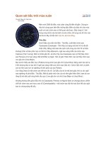
1. Ideal Diode
An ideal diode is a two-terminal device defined by the following non-linear (current-
voltage) iv-characteristic:
+ v -
i
Anode
Cathode
Circuit Symbol
"brick wall""arrowhead"
0
Reverse
Bias
Forward
Bias
i
v
"electronic check valve"
"FB""RB"
Forward Biased Regime (v>0): Zero voltage drop occurs across a forward-biased ideal
diode (i.e., the diode behaves like an ideal short circuit).
Reverse Bias Regime (v≤0): Zero current flows in a reverse-biased ideal diode (i.e., the
diode behaves like an open circuit).
Note: From the above, it follows that zero power dissipation occurs in an ideal diode.
2. Real Diode
The physics of real pn junctions leads to the following (non-ideal) iv-characteristics:
(see Figs. 3.7, 3.8 in S&S 4th ed. - Real Diode current-voltage characteristics)
Forward Bias Regime (v>0):
The iv-characteristic in this region is closely approximated by
i = I
s
e
v/ nV
T
− 1
( )
where I
s
=Reverse Saturation Current (also called Scale Current in S&S text, since
I
s
∝A). Typically, I
s
is very small: pA for small Si diodes, fA for IC diodes.
1
Sedra & Smith,
4th Ed.
Sedra & Smith,
4th Ed.
2
I
s
= Aq
D
p
L
p
N
D
+
D
n
L
n
N
A
n
i
2
=constant for a given diode at a given temperature.
n=empirical constant (typically 1≤n≤2, depending on the type of diode and its
physical structure), which accounts for carrier gen/recomb in the depletion region
(higher J's and fewer centers in IC's, so n is closer to 1, cf. 2 for discrete devices).
Actually n depends on the magnitude of v & so is not strictly constant.
V
T
=Volt-Equivalent of Temperature or Thermal Voltage.
The Thermal Voltage can also be written explicitly as
V
T
=kT/q
where k=Boltzmann's constant (also written k
B
)=1.38x10
-23
J/K
T=Absolute Temperature (K)
q=Electronic Charge=1.602x10
-19
C.
e.g. At 20 ˚C, V
T
=25.2 mV ≈25 mV (used throughout S&S text and this course).
Clearly, for larger currents (where i>>I
s
or v>10nV
T
)
i ≅I
s
e
v / nV
T
which has been found to hold over several (≈7) decades of current.
The diode equation has 2 parameters and hence 2 measurements are required to determine I
s
and n empirically.
Consider the change in diode voltage drop due to a change in diode current:
Let I
1
= I
s
e
V
1
/nV
T
and I
2
= I
s
e
V
2
/nV
T
,
then I
1
/I
2
= e
V
1
− V
2
( )
/nV
T
or V
1
− V
2
= 2.303nV
T
log(I
1
/I
2
) - so slope of log plot yields value of n
i.e., the diode voltage changes by ≈2.3nV
T
for every decade change in diode current
(e.g., ≈60 mV for n=1 @20 ˚C).
In practice, if n is unknown, a common "rule of thumb" is to assume V
1
-V
2
≈100
mV/decade @ 20 ˚C, which yields n≈1.7 (in this course, if n is unknown, use n=1).
Reverse Bias Regime (V
ZK
≤ v≤0):
The reverse diode current is also described by
i = I
s
e
v/ nV
T
− 1
( )
3
but, since e
v/nV
T
→ 0 when v<<0, this expression reduces to
i≈-I
s
so the current "saturates" at -I
s
when the diode is significantly reverse biased (and hence the
name Reverse Saturation Current).
Note that the actual reverse current may be mA due to leakage over the surface of the diode
and additional carriers generated by collisions in the depletion region.
Breakdown Regime (v≤V
ZK
):
A reversible breakdown occurs when v<V
ZK
, which gives rise to the steep gradient in the
iv-characteristic in this region.
There are actually two distinct breakdown mechanisms:
1. Zener breakdown (predominates if -5≤V
ZK
≤-2 V) - does not involve collisions (direct disruption
of covalent bonds due to E across depletion region; occurs in heavily doped semiconductors, since higher
doping results in narrower depletion region
2. Avalanche Breakdown (predominates if V
ZK
<-7 V) - lightly doped semiconductors
A combination of these mechanisms is usually responsible in diodes where -7≤V
ZK
≤-5 V.
Diodes specifically designed to be operated in this breakdown regime are typically called
Zener diodes, regardless of which mechanism dominates.
(see Fig. 3.31 in S&S 4th ed. - Zener diode characteristic & circuit symbol - note "reverse"
polarity compared to signal diodes)
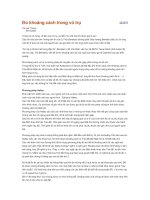
Temperature Dependence:
Forward Bias Regime: At a given (constant) diode current, v exhibits a linear temperature
dependence due to the dependence of I
s
and V
T
on temp.
Rule of Thumb: Typically, the iv-characteristic shifts approx. -2 mV/˚C.
i
v
-2 mV/˚C
T2
T1
T2>T1
Reverse Bias Regime: The temp. dependence of the reverse current is that of I
s
.
Rule of Thumb: Typically, I
s
approx. doubles for every 10 ˚C increase in Temp.
Sedra & Smith,
4th Ed.
4
Breakdown Regime: The temperature coefficient of Zener diodes depends on both
voltage and current. Note: sometimes "TC" is called "Temco".
TC mV/˚C
i
Vz=6.8 V
Vz=5.1 V
0
Note: A 6.8 V Zener diode exhibits a TC≈+2 mV/˚C, which is complementary to a
forward biased diode!
0.7 V 6.8 V
≈7.5 V+ -
← nearly independent of T (over a useful range of i)
3. Diode Models & Analysis of Diode Circuits
e.g. Consider the following circuit:
R
10 kΩ
V
+
-
10 V
V
I
V
DD
=
IR
+
V (1)
I
=
I
S
(e
V/nVT
−1) (2)
DD
Exact Solution: If I
s
and n for the diode are known, then (1) and (2) can be solved
simultaneously to obtain I and V.
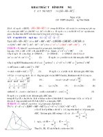
Graphical Solution: If data are available, then (1) and (2) could be plotted and I and V
could be obtained from the intersection.
/R
v
i
0
I
V
Load Line
Quiescent (Operating) Point, Q
a similar graphical method is used
for the analysis of transistors - later
V
DD
V
DD
5
Approximate Solution: If an exact solution is not required, an approximation can be found
using an iterative approach:
e.g. Suppose the diode is specified as exhibiting a 0.7 V drop at 1 mA (in the text, this
is sometimes called "a 1-mA diode" for short), with n=1.8.
step 0) Assume that the diode can be adequately described by I ≅ I
s
e
V/nV
T
(2')
Substitute I=1 mA and V=0.7 V (from specs.) to calculate I
s
I
s
= 10
−3
e
−0.7/nV
T
which yields
I =10
−3
e
(V−0.7)/nV
T
or V = nV
T
ln(I /10
−3
) + 0.7 (2'')
step 1) As a first guess/approximation, assume V=0.7 V,
then I =
V
DD
− V
R
=
10 V - 0.7 V
10 kW
= 0.93 mA
The accuracy can be improved by iterating between (1) and (2'') as follows:
step 2) Substitute the value of I found in step 1 into (2'') to calculate a new value for V
V = (1.8)(0.025)ln(0.93) + 0.7 = 696.7 mV
step 3) Substitute this value back into (1), to calculate a new value for I
I =
10 V - 0.697 V
10 kW
= 0.9303 mA
step 4) Continue iterating between (1) and (2'') until
(I
n
− I
n−1
)
I
n
≤ 1% (arbitrary precision)
Graphical representation of iterative method:
V /R
V
v
i
0
Load Line (1)
1
2
3
4
5
.7.697
.93
.9303
(2)
DD
DD