Tài liệu GSM, cdmaOne and 3G Systems P4 docx
Bạn đang xem bản rút gọn của tài liệu. Xem và tải ngay bản đầy đủ của tài liệu tại đây (778.2 KB, 80 trang )
Chapter
4
The cdmaOne System
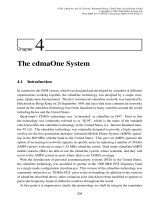
4.1 Introduction
In contrast to the GSM system, which was designed and developed by a number of different
organisations working together, the cdmaOne technology was designed by a single com-
pany, Qualcomm Incorporated. The first commercial cdmaOne network was launched by
Hutchison in Hong Kong on 28 September 1995 and since that time commercial networks
based on the cdmaOne technology have been launched in many countries around the world
including Korea and the United States.
Qualcomm’s CDMA technology was ‘re-branded’ as cdmaOne in 1997. Prior to this
the technology was commonly referred to as ‘IS-95’, which is the name of the standard
which describes the cdmaOne technology in the United States (i.e. Interim Standard num-
ber 95 [1]). The cdmaOne technology was originally designed to provide a high capacity
overlay for the first generation analogue Advanced Mobile Phone System (AMPS) operat-
ing in the 800 MHz cellular band in the United States. This gave an AMPS operator the
option of increasing its network capacity in specific areas by replacing a number of 30 kHz
AMPS carriers with one or more 1.25 MHz cdmaOne carrier. Dual mode cdmaOne/AMPS
mobile stations (MSs) are able to use the cdmaOne system, where available, and they will
revert to the AMPS system in areas where there is no CDMA coverage.
With the introduction of personal communications systems (PCS) in the United States,
the cdmaOne technology was modified to operate in the 1900 MHz PCS frequency band
in a single mode configuration citecdma-pcs. This version of the cdmaOne technology was
commonly referred to as ‘CDMA-PCS’ prior to the re-branding. In addition to the versions
of cdmaOne described above, other variations exist which have been modified to operate in
particular frequency bands in different countries throughout the world.
At this point it is important to clarify the terminology we shall be using in the remainder
205
GSM, cdmaOne and 3G Systems. Raymond Steele, Chin-Chun Lee and Peter Gould
Copyright © 2001 John Wiley & Sons Ltd
Print ISBN 0-471-49185-3 Electronic ISBN 0-470-84167-2
206
CHAPTER 4. THE CDMAONE SYSTEM
of this chapter. We shall use the term ‘IS-95’ to describe the CDMA system operating in
the US cellular band (800 MHz) and we shall use the term ‘CDMA-PCS’ to describe the
PCS system operating in the 1.9 GHz band. In many cases our discussion will relate to both
systems and in this case we shall use the brand name cdmaOne to refer to both versions of
the system simultaneously.
It is important to note that the cdmaOne system is basically an air-interface standard, in
contrast to the GSM system which is specified up to the network gateway.
4.2 The cdmaOne Radio Interface
4.2.1 Operating frequencies
Before we proceed, we must make a point about terminology. In Europe the transmission
path from the network towards the mobile station (MS) is known as the down-link and the
transmission path from the MS to the network is known as the up-link. However, in North
America the down-link and up-link are known as the forward and reverse links, respectively.
Since IS-95 and CDMA-PCS are North American systems, we will use the North American
terms throughout this chapter.
The IS-95 system operates in the US cellular frequency band. This band has been sub-
divided into five blocks and distributed between two operators, A and B, thereby allowing
two different cellular systems to be supported within the same geographical area. The US
cellular spectrum allocations in the 800 MHz band are shown in Table 4.1
The IS-95 system uses frequency division duplex (FDD), i.e. the forward link and reverse
link transmissions occur in different frequency bands. The duplex separation used in IS-
95 (and AMPS) is 45 MHz and the carrier spacing is 1.25 MHz. We note that the IS-
95 system has been conceived to operate in a dual mode configuration with the existing
analogue AMPS systems in the United States and for the analogue carriers to be gradually
replaced with CDMA carriers. In situations where a single CDMA carrier is placed in a
Table 4.1 : The US cellular bands.
System Frequencies (MHz)
Reverse link Forward link
A
00
824.040–825.000 869.040–870.000
A 825.030–834.990 870.030–879.990
B 835.020–844.980 880.020–889.980
A
0
845.010–846.480 890.010–891.480
B
0
846.510–848.970 891.510–893.970
4.2. THE CDMAONE RADIO INTERFACE
207
band occupied by an analogue system, spectral guard bands must be provided between the
CDMA service and the existing analogue service. Consequently, a single CDMA carrier
operating within an analogue AMPS band will require around 1.8 MHz of spectrum.
The CDMA carrier numbering scheme for IS-95 is the same as that used for AMPS and
isshowninTable4.2,whereN is the channel number, f
u
is the reverse link frequency and
f
d
is the forward link frequency.
The table shows that the channel numbering is based on the AMPS carrier spacing of
30 kHz which allows the network operator to position a CDMA carrier at any point within
the AMPS band with an accuracy of 30 kHz. It is important to note that a single 1.25 MHz
CDMA carrier will occupy the same spectrum as around 40 AMPS carriers and, therefore,
the channel numbers of adjacent CDMA carriers will differ by around 40. The CDMA car-
riers must be positioned in such a way as to allow sufficient guard bands between other ser-
vices operating above and below the cellular band and between the A and B services. Con-
sequently, the CDMA carriers are limited to using the channel numbers shown in Table 4.3.
The CDMA-PCS system has been designed to operate in the 1.9 GHz PCS band in the
United States. This band is sub-divided into three 2
15 MHz blocks (i.e. 15 MHz for
the reverse link and 15 MHz for the forward link) and three 2
5 MHz blocks. The PCS
spectrum allocations are shown in Table 4.4.
The duplex spacing in the 1.9 GHz PCS band in the United States is 80 MHz and the
channel numbering scheme is shown in Table 4.5, where N is the channel number, f
u
is the
reverse link frequency and f
d
is the forward link frequency. This shows that the CDMA
carriers may be placed anywhere within the PCS band in steps of 50 kHz. Each 1.25 MHz
CDMA-PCS carrier will occupy 25 of these 50 kHz PCS channels and the channel numbers
of adjacent CDMA-PCS carriers will differ by 25. The CDMA-PCS carriers must be posi-
tioned to ensure that there are sufficient spectral guard bands between the different operator
frequency blocks (unless adjacent blocks are allocated to the same operator) and between
the systems that occupy the frequency bands above and below the PCS band. For this reason
a number of preferred CDMA channel numbers have been defined for each block, and these
are shown in Table 4.6.
Having identified the operating frequencies of the IS-95 and CDMA-PCS systems we will
Table 4.2 : IS-95 channel numbering.
Band Frequency (MHz) Channel numbers
Reverse link f
u
=
0
:
030N
+
825
:
000 1
N
777
f
u
=
0
:
030
(
N
1023
)+
825
:
000 1013
N
1023
Forward link f
d
=
0
:
030N
+
870
:
000 1
N
777
f
d
=
0
:
030
(
N
1023
)+
870
:
000 1013
N
1023
208
CHAPTER 4. THE CDMAONE SYSTEM
Table 4.3 : Available channel numbers for IS-95 carriers.
System A 1 - 311
689 - 694
1013 - 1023
System B 356 - 644
739 - 777
Table 4.4: PCS spectrum allocations.
Frequency (MHz)
Block Reverse link Forward link
A 1850–1865 1930–1945
D 1865–1870 1945–1950
B 1870–1885 1950–1965
E 1885–1890 1965–1970
F 1890–1895 1970–1975
C 1895–1910 1975–1990
Table 4.5 : PCS channel numbers.
Band Frequency (MHz) Channel numbers
Reverse link 1850
:
000
+
0
:
050 N 0
N
1200
Forward link 1930
:
000
+
0
:
050 N 0
N
1200
Table 4.6: CDMA-PCS preferred channel numbers.
Block Channel numbers
A 25, 50, 75, 100, 125, 150, 175, 200, 225, 250, 275
D 325, 350, 375
B 425, 450, 475, 500, 525, 550, 575, 600, 625, 650, 675
E 725, 750, 775
F 825, 850, 875
C 925, 950, 975, 1000, 1025, 1050, 1075, 1100, 1125, 1150, 1175
4.2. THE CDMAONE RADIO INTERFACE
209
now examine the physical layer of the radio interface. In contrast to the GSM system, the
coding systems employed on the reverse link and forward link are very different and, for
this reason, we shall examine each link separately.
4.2.2 The cdmaOne Forward link
The forward link consists of the base station (BS) transmitter, the radio channel and the
MS receiver. The cdmaOne system supports four different types of forward channels. The
pilot channel is continuously transmitted by each CDMA carrier and is used by the MS
to identify the BS. The pilot channel also acts as a cell beacon and is used by MSs in
neighbouring cells to assess the suitability of the cell for handover. In this respect the pilot
channel in the cdmaOne system may be likened to the BCCH carrier in the GSM system.
The pilot carrier of the serving cells is also used by the MS as a coherent reference in the
demodulation process and in the reverse link power control algorithm.
Another forward channel is the synchronisation channel which, as its name suggests,
allows the MS to achieve time synchronisation with the BS and the network. The synchro-
nisation channel also carries information relating to system time, and the contents of the
BS’s internal registers which are used in the coding, spreading and encryption processes.
There are also a number of paging and traffic channels. The paging channels are used to
page MSs to alert them to an incoming call. The paging channel is also used to carry general
network information and channel assignment messages. The traffic channels are assigned
to the users as required and they may carry speech or user data at bit rates of up to 9.6 kb/s
for IS-95 and 14.4 kb/s for CDMA-PCS.
Each forward channel on a CDMA carrier is assigned a different 64-bit Walsh code, and
these codes are shown in Figure 4.1. Each row of the table represents a different 64-bit
Walsh code with the bit positions shown at the top of the table, and the index of the Walsh
code shown in the left-hand column. We note that these codes are orthogonal, i.e. the value
of any two codes, multiplied together and summed over a period of 64 chips, is zero, pro-
vided the ‘0’ bits are replaced by a ‘
1’ and the ‘1’ bits are replaced by a ‘+1’. Multiplying
a Walsh code by itself produces a constant level of +1 when the two codes are in time syn-
chronisation. We note that although the codes shown in Figure 4.1 are true Walsh codes
they are not indexed (or numbered) in the conventional manner. A Walsh code’s index is
normally given by the number of transitions that occur between the different levels during a
code period (i.e. 64 chips). In the cdmaOne specifications, however, the Walsh codes have
been numbered as shown in Figure 4.1. In this discussion we will always use the code index
numbers shown in Figure 4.1 to avoid confusion and we will refer to the codes as Walsh
Hadamard (WH) codes.
The full block diagram of the cdmaOne BS transmitter is shown in Figure 4.2. Each
channel in the cdmaOne forward link uses a different coding scheme depending on the
210
CHAPTER 4. THE CDMAONE SYSTEM
Code Index
Bit Position
1111111111122222222223333333333444444444455555555556666
0123456789012345678901234567890123456789012345678901234567890123
0 0000000000000000000000000000000000000000000000000000000000000000
1 0101010101010101010101010101010101010101010101010101010101010101
2 0011001100110011001100110011001100110011001100110011001100110011
3 0110011001100110011001100110011001100110011001100110011001100110
4 0000111100001111000011110000111100001111000011110000111100001111
5 0101101001011010010110100101101001011010010110100101101001011010
6 0011110000111100001111000011110000111100001111000011110000111100
7 0110100101101001011010010110100101101001011010010110100101101001
8 0000000011111111000000001111111100000000111111110000000011111111
9 0101010110101010010101011010101001010101101010100101010110101010
10 0011001111001100001100111100110000110011110011000011001111001100
11 0110011010011001011001101001100101100110100110010110011010011001
12 0000111111110000000011111111000000001111111100000000111111110000
13 0101101010100101010110101010010101011010101001010101101010100101
14 0011110011000011001111001100001100111100110000110011110011000011
15 0110100110010110011010011001011001101001100101100110100110010110
16 0000000000000000111111111111111100000000000000001111111111111111
17 0101010101010101101010101010101001010101010101011010101010101010
18 0011001100110011110011001100110000110011001100111100110011001100
19 0110011001100110100110011001100101100110011001101001100110011001
20 0000111100001111111100001111000000001111000011111111000011110000
21 0101101001011010101001011010010101011010010110101010010110100101
22 0011110000111100110000111100001100111100001111001100001111000011
23 0110100101101001100101101001011001101001011010011001011010010110
24 0000000011111111111111110000000000000000111111111111111100000000
25 0101010110101010101010100101010101010101101010101010101001010101
26 0011001111001100110011000011001100110011110011001100110000110011
27 0110011010011001100110010110011001100110100110011001100101100110
28 0000111111110000111100000000111100001111111100001111000000001111
29 0101101010100101101001010101101001011010101001011010010101011010
30 0011110011000011110000110011110000111100110000111100001100111100
31 0110100110010110100101100110100101101001100101101001011001101001
32 0000000000000000000000000000000011111111111111111111111111111111
33 0101010101010101010101010101010110101010101010101010101010101010
34 0011001100110011001100110011001111001100110011001100110011001100
35 0110011001100110011001100110011010011001100110011001100110011001
36 0000111100001111000011110000111111110000111100001111000011110000
37 0101101001011010010110100101101010100101101001011010010110100101
38 0011110000111100001111000011110011000011110000111100001111000011
39 0110100101101001011010010110100110010110100101101001011010010110
40 0000000011111111000000001111111111111111000000001111111100000000
41 0101010110101010010101011010101010101010010101011010101001010101
42 0011001111001100001100111100110011001100001100111100110000110011
43 0110011010011001011001101001100110011001011001101001100101100110
44 0000111111110000000011111111000011110000000011111111000000001111
45 0101101010100101010110101010010110100101010110101010010101011010
46 0011110011000011001111001100001111000011001111001100001100111100
47 0110100110010110011010011001011010010110011010011001011001101001
48 0000000000000000111111111111111111111111111111110000000000000000
49 0101010101010101101010101010101010101010101010100101010101010101
50 0011001100110011110011001100110011001100110011000011001100110011
51 0110011001100110100110011001100110011001100110010110011001100110
52 0000111100001111111100001111000011110000111100000000111100001111
53 0101101001011010101001011010010110100101101001010101101001011010
54 0011110000111100110000111100001111000011110000110011110000111100
55 0110100101101001100101101001011010010110100101100110100101101001
56 0000000011111111111111110000000011111111000000000000000011111111
57 0101010110101010101010100101010110101010010101010101010110101010
58 0011001111001100110011000011001111001100001100110011001111001100
59 0110011010011001100110010110011010011001011001100110011010011001
60 0000111111110000111100000000111111110000000011110000111111110000
61 0101101010100101101001010101101010100101010110100101101010100101
62 0011110011000011110000110011110011000011001111000011110011000011
63 0110100110010110100101100110100110010110011010010110100110010110
Figure 4.1: The Walsh Hadamard transform (WHT) matrix of order 64.
4.2. THE CDMAONE RADIO INTERFACE
211
requirements of the channel. In the following sections we shall examine each channel sep-
arately.
4.2.2.1 The pilot channel
The pilot channel is the simplest of all forward link channels, since it always carries an ‘all
zero’ bit stream. Referring to Figure 4.2, this ‘all zero’ signal is EXORed (shown as a
in
the figure) with the Walsh code with an index of 0 in Figure 4.1, i.e. a series of logical 0s.
The result of this operation is another ‘all zero’ bit stream which is then divided into two
and each part is EXORed with one of two different pseudo-random noise (PN) sequences,
known as PNI, for the in-phase component, and PNQ, for the quadrature component. These
two sequences are 2
15
bits in length and they are based on the following characteristic
polynomials:
PNI
(
x
) =
x
15
+
x
13
+
x
9
+
x
8
+
x
7
+
x
5
+
1
(4.1)
PNQ
(
x
) =
x
15
+
x
12
+
x
11
+
x
10
+
x
6
+
x
5
+
x
4
+
x
3
+
1
:
(4.2)
The sequences may be generated using a 15-bit feedback register. The maximal length
sequences based on Equations (4.1) and (4.2) will be 2
15
1 bits in length. The sequences
are extended to 2
15
length sequences by inserting a ‘0’ after 14 consecutive 0’s, which will
occur once for each repetition of the code.
The two PN sequences are generated at a chip rate of 1.2288 Mchips/s and the period will
be
2
15
=
122880
=
32768
=
1228800
=
26
:
666 ms (4.3)
which results in exactly 75 PN sequence repetitions every 2 s.
EXORing the PN sequences with an all zeros data sequence will leave the PN sequences
unchanged. The two sequences are then pulse shaped using low pass filters. The character-
istics of the low pass filters are shown in Figure 4.3 in the form of a response mask taken
from the specifications [1, 2]. In the diagram, S
(
f
)
is the frequency response of the filter.
The filter pass band extends from 0 to f
p
and the stop band extends from f
s
to ∞. Within
the pass band the filter response is prescribed within the limits
δ
1
, and within the stop
band the filter response shall be less than
δ
2
. The values for each of the parameters are
δ
1
=1.5 dB, δ
2
=40 dB, f
p
=590 kHz, and f
s
=740 kHz.
The two data sequences are then multiplied by two quadrature carriers, PNI and PNQ, and
the resulting signals are summed to produce a phase modulated carrier signal. The relation-
ship between the input bit sequence and the resulting carrier phase is shown in Table 4.7.
These phase transitions may be produced by translating the I and Q bit streams such that
a 0 in the original bit stream is replaced by +1 level, and a 1 in the original bit stream is
replaced by a
1 level. The constellation diagram is shown in Figure 4.4.
212
CHAPTER 4. THE CDMAONE SYSTEM
W
i
19.2kb/s
W
19.2kb/s
j
W
32
4.8ksym/s
19.2ksym/s
W
0
CDMA
Transmitted
Signal
Combining
Weighting and
Quadrature
Modulation
Pilot
Channel
(all 0’s)
Sync
Channel
Data
1.2kb/s
Convolutional
Encoder and
Repetition
Repetition
Encoder and
Convolutional
Repetition
Encoder and
Convolutional
Block
Interleaver
Block
Interleaver
Block
Interleaver
Paging
Channel Data
9.6kb/s
4.8kb/s
Forward
Traffic Data
9.6kb/s
4.8kb/s
2.4kb/s
1.2kb/s
Paging
Channel Mask
Channel Mask
Traffic
Long PN
Generator
Long PN
Generator
Symbol Scrambler
and Power Control
Multiplexer
Symbol
Scrambler
Power
Control Bits
Symbol
Cover
Symbol
Cover
Symbol
Cover
PNI
1.2288Mchips/s
1.2288Mchips/s
PNQ
Figure 4.2: Block diagram of a cdmaOne BS transmitter (rate set 1).
1
1
2
0
20 log |S(f)|
ff
ps
frequency
Figure 4.3: Pulse shaping filter requirements.
4.2. THE CDMAONE RADIO INTERFACE
213
Q-Channel
(1,1)
(1,0)
I-Channel
(0,1)
(0,0)
(I,Q)
Figure 4.4: The phase constellation at the BS transmitter.
Table 4.7 : I and Q data to phase transition mapping.
IQPhase
00
π
4
10
3π
4
11
3π
4
01
π
4
214
CHAPTER 4. THE CDMAONE SYSTEM
We have described the construction of the pilot channel as it has been shown in the spec-
ifications. However, in practice the pilot channel is merely produced by modulating the
PNI and PNQ sequences onto two quadrature carriers; the use of Walsh code 0 and an ‘all
zero’ data sequence is irrelevant. We have also assumed that the translation from digital bits
(0 and 1) to logical levels (
1) occurs just prior to quadrature modulation; however, this
translation may occur at an earlier stage. For example, the PNI and PNQ sequences could
be produced as logical levels directly.
Having described the construction of the pilot channel we now examine its functions.
One of the main functions of the pilot channel is to allow the MS to detect and identify the
BSs. Since all BSs use the same PN sequences and the same carrier frequency, the only
way in which the different pilot channels may be distinguished is by the phase of their PN
sequences. In IS-95, each BS within a geographical area will use a different time offset for
the PN sequence and this offset will be defined in integer multiples of 64 chips.
For the PN offset to have any meaning across the system it must be referenced to a com-
mon timing source. This requirement means that all BSs within a network must be time
synchronised. This is currently achieved using global positioning system (GPS) satellite
links as a source of universal coordinated time (UTC). The network system time is synchro-
nised to UTC; however, it differs from UTC because the system time does not include the
leap seconds that are added to UTC. The even seconds of system time are also important
when we consider frame synchronisation. These represent points in system time when the
number of accumulated seconds is divisible by two, i.e. every other second.
The 2
15
=
32768
=
512
64 length PN sequences allow 512 different offsets of 64 chips
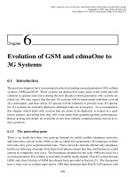
from 0 (i.e. zero offset PN sequence) to 511. At switch-on, an MS will sweep a searcher
correlator over all possible pilot PN offsets to identify the different BSs within its local area.
The amplitude of the correlator output will indicate the strength of the BS using a given pilot
PN offset. An example of a searcher correlator output is shown in Figure 4.5, where both
the in-phase (I) and quadrature (Q) outputs are shown. The figure shows that the MS has
identified four strong BSs within the geographical area.
The pilot signal is also used by the MS to provide a coherent reference in the demodulation
of other signals transmitted on the same CDMA carrier. This is possible because the MS
is able to extract the RF carrier phase information from the pilot signal, and this will be
constant for all the channels on a single CDMA RF carrier.
The MS also uses the pilot signals to assess the suitability of neighbouring BSs for han-
dover and, in this respect, the pilot signal is similar to the BCCH carrier in the GSM system.
The MS also uses the pilot channel to estimate what reverse transmitter power it should ini-
tially use. This estimate is known as the open-loop estimate, and once the MS is in a call, it
will continue to be used in conjunction with a closed-loop power control mechanism to al-
low more accurate control of the MS transmitted power to be made and over a wide dynamic
4.2. THE CDMAONE RADIO INTERFACE
215
Time
Amplitude
Q
I
Figure 4.5: An example of a searcher correlator output.
range in the presence of fading.
4.2.2.2 The synchronisation channel
The synchronisation channel carries the information required to allow the MS to synchro-
nise with a given BS. The channel data rate is 1.2 kb/s. The information data on the syn-
chronisation channel, or sync channel, is one-half rate convolutionallyencoded using a code
with a constraint length of nine defined by the following generator polynomials:
g
0
=
1
+
D
+
D
2
+
D
3
+
D
5
+
D
7
+
D
8
g
1
=
1
+
D
2
+
D
3
+
D
4
+
D
8
:
(4.4)
This code has a minimum free distance of 12; the interested reader is referred to Refer-
ence [3] for a detailed discussion of the operation and performance of this type of forward
error correcting code.
This coding process results in a coded symbol rate of 2.4 ksymbols/s. Each symbol is
repeated once to produce a symbol rate of 4.8 ksymbols/s. The symbols are then block
interleaved over 128 symbols, i.e. over one period of the pilot code of 26.66 ms, and the re-
sulting signal is then EXORed with the Walsh code that has an index of 32 (see Figure 4.1).
The Walsh code is generated at a chip rate of 1.2288 Mchips/s and consists of 32 zero chips
followed by 32 one chips.
We note that this Walsh code will not effectively spread the data signal over the full band
of 1.25 MHz (i.e. 1.2288 Mchips/s) since its polarity changes only twice per 64 chip cycle.
To achieve spectral spreading over the channel bandwidth of 1.25 MHz the synchronisation
signal is EXORed with both the PNI and PNQ sequences, and the resulting signals are
passed through two low pass pulse shaping filters that are identical to those used on the
pilot channel. The filtered signals modulate two quadrature carriers following the same
216
CHAPTER 4. THE CDMAONE SYSTEM
phase mapping conventions that were used on the pilot channel (see Table 4.7).
The sync channel will use the same PNI and PNQ offsets as the pilot channel on the same
carrier. In this way the MS is able to associate the sync channel with the correct pilot chan-
nel, and in turn, with the correct cell. The sync channel carries a 15-bit system identification
number (SID) and a 16-bit network identification number (NID). It also carries the pilot PN
offset of the cell (PILOT
PN), the contents of the long code generator (LC STATE, this will
be described later) and the system time (SYS
TIME).
As we have already seen, the sync channel data is generated at a rate of 1.2 kb/s or, to be
more specific, one frame of 32 bits every 26.66 ms. Each sync channel frame is aligned with
the start of the PN sequences, and consequently the MS may acquire the sync channel frame
timing information from the pilot channel. The interleaving on the sync channel is also
performed over each 26.66 ms frame. Only one message is transmitted on the sync channel;
the structure of the sync channel message is shown in Figure 4.6. The first eight bits of the
message give the length of the message (MSG
LENGTH) in octets. This length will include
the 8-bit MSG
LENGTH parameter itself, the message body and a 30-bit checksum. The
message body contains the sync channel information (e.g. LC
STATE and SYS TIME). The
sync channel message is protected by a 30-bit cyclic redundancy checksum (CRC) which is
appended at the end of the message and is defined by the following generator polynomial:
g
(
x
) =
x
30
+
x
29
+
x
21
+
x
20
+
x
15
+
x
13
+
x
12
+
x
11
+
x
8
+
x
7
+
x
6
+
x
2
+
x
+
1
:
(4.5)
The CRC is generated for both the 8 MSG
LENGTH bits and the message body. It is
used by the MS to check for any errors in the sync channel message that remain uncorrected
following the one-half rate convolutional forward error correction (FEC) decoding.
The sync channel message is mapped onto the sync channel frames as shown in Figure 4.6.
Each frame consists of a single-bit start-of-message (SOM) flag followed by 31 information
bits. The 31 information bits are used to carry the contents of the sync channel message,
while the SOM flag is used to indicate the point at which a new message begins. Setting
the SOM flag to a ‘1’ indicates that the information contained in the remainder of the frame
is the start of a new message. When the SOM flag is set to a ‘0’ this indicates that the
information contained in the frame is part of a message that began in an earlier frame.
The sync channel frames are formed into superframes, which consist of three consecu-
tive frames. The superframe is 80 ms in length, as shown in Figure 4.6. A sync channel
message will always be mapped onto an integer number of sync channel superframes, and
consequently a certain amount of padding is added at the end of the message to fill-up the
final superframe. This also means that a new sync channel message will only begin at the
superframe boundaries. The sync channel superframes are aligned such that, for a zero off-
4.2. THE CDMAONE RADIO INTERFACE
217
MSG_LENGTH
Message Body CRC Padding
31 Information Bits
The Sync Channel Message
1 Superframe = 3 Frames = 80ms
S
=0 =0
S
=0
S
=0
S
=0
S
=1
S
1 Bit
Start-of-Message
(SOM) Flag
1 Sync Channel
Frame =
26.67ms
SOM Flag (set to
1 to signify the
start of a
message)
8 - bits
2-2002 - bits
30
bits
Figure 4.6: The sync channel structure.
set PN sequence, the start of a superframe will always coincide with the even seconds of
system time. In the case of a non-zero PN offset, the start of a superframe will always align
with a point equal to the PN offset after the even second marks of system time.
The even seconds of system time, which are called the even second marks in the specifi-
cations, are very important since they are used as a timing reference for the PN offsets. The
PN sequences of a zero offset pilot will always start on the even second marks. For a pilot
with a non-zero PN offset, the PN sequences will start at a time equal to the PN offset after
the even second marks. This is shown in Figure 4.7.
The information in the sync channel message is time sensitive, i.e. it is only valid at a
specific point in time, and it is important that the MS understands the precise time instant
to which the information refers. In the case of a pilot with a zero PN offset, the information
contained in the sync channel message will become valid 320 ms, which is equal to four
superframe periods, after the end of the last superframe containing a part of the sync chan-
nel message. Alternatively, we can say that the LC
STATE and the SYS TIME parameters
contained in the sync channel message refer to a time 320 ms after the last message super-
frame. Where the pilot PN offset is not zero, the content of the message becomes valid at
a time equal to 320 ms minus the PN offset after the last superframe carrying the message.
This is shown in Figure 4.8.
4.2.2.3 The paging channel
The paging channel performs a number of different functions in addition to carrying pag-
ing messages between the network and an MS. It conveys general system information (e.g.
the handover thresholds), access information (e.g. the maximum allowed number of unsuc-
218
CHAPTER 4. THE CDMAONE SYSTEM
2 Seconds
75 Pilot PN Cycles
80ms
Pilot PN Offset
Pilot PN Offset
Even Second
Marks
Zero pilot
offset
Sync Channel
superframes for
zero PN offset
Non-zero
pilot offset
Sync Channel
superframes for a
non-zero PN offset
Figure 4.7: Pilot and sync channel timing.
cessful access attempts), a list of the surrounding cells and channel assignment messages.
Referring to Figure 4.2, we note that the paging channel information is generated at a data
rate of either 9.6 kb/s or 4.8 kb/s. All paging channels within a system use the same data
rate. The paging channel data is one-half rate convolutionally encoded using the same code
as that employed on the sync channel. This results in a symbol rate of either 19.2 ksymbols/s
or 9.6 ksymbols/s, depending on the input data rate.
The code symbols for the lower data rate are repeated once to produce a constant sym-
bol rate of 19.6 ksymbols/s regardless of the input data rate. Where the input data rate is
9.6 kb/s, the repetition process is not performed. The resulting modulation symbols are
then block interleaved over a period of 20 ms, which is equivalent to 384 symbols at a rate
of 19.2 ksymbols/s. We note that although the paging channel data is formed into 20 ms
frames for the purposes of interleaving, the convolutional encoding process treats the data
as a continuous bit stream. This means that no encoder tail bits are added between blocks
prior to convolutional encoding in order to reset the encoder and the last bits of one block
will influence the code symbols for the next block. This is in contrast to the convolutional
encoding schemes used in GSM and on the cdmaOne traffic channel which use encoder tail
4.2. THE CDMAONE RADIO INTERFACE
219
.....
.....
Pilot PN Offset
The data contained
in a Sync Channel
Message which ends
in this superframe
becomes valid at this point,
320ms=4 superframes later
Sync Channel
superframes for a
zero pilot PN offset
320ms-pilot PN offset later
becomes valid at this point,
The data contained
in a Sync Channel
Message which ends
in this superframe
Sync Channel
superframes for a
non-zero pilot PN offset
Figure 4.8: The content of the sync channel message.
bits to reset the coder between frames.
Referring to Figure 4.2, we note that the interleaved code symbols are scrambled by EX-
ORing them with a data stream generated at a rate of 19.2 ksymbols/s. This scrambling
sequence is derived from a higher rate sequence produced by a long code generated at
1.2288 Mchips/s. This long code is 2
42
1 bits in length and is formed by a 42-bit feedback
register and associated logic, as shown in Figure 4.9. The characteristic polynomial for the
feedback register is
p
(
x
) =
x
42
+
x
35
+
x
33
+
x
31
+
x
27
+
x
26
+
x
25
+
x
22
+
x
21
+
x
19
+
x
18
+
x
17
+
x
16
+
x
10
+
x
7
+
x
6
+
x
5
+
x
3
+
x
2
+
x
+
1
:
(4.6)
The long PN code is produced by logically ANDing the content of the 42-bit shift register,
at each clock cycle, with a 42-bit mask, and then performing a modulo-2 addition of the
resulting bits, as shown in Figure 4.9. The content of the 42-bit long code mask will vary
depending on the type of channel. The shift register is clocked at a rate of 1.2288 MHz and
the resulting PN code is generated at a rate of 1.2288 Mchips/s.
In the case of the paging channel, the construction of the long code mask is shown in
Figure 4.10. The three-bit PCN parameter gives the paging channel number and this will
be different for each paging channel on a particular carrier. Three bits allow a maximum
220
CHAPTER 4. THE CDMAONE SYSTEM
1
2
3
4
5 6
7
8 9
10
39
40
41
42
Modulo-2 Addition
42-bit Long Code Mask
LSB MSB
User Long Code PN
Sequence at
1.2288Mchips/s
42
Figure 4.9: The long code generator.
of eight (0 to 7) paging channels per CDMA carrier; however, the PCN parameter may
not take a value of 0 and, therefore, there will be a maximum of seven paging channels on
each CDMA carrier. The paging channel mask also contains the nine-bit pilot PN offset
(PN
OFFSET) in use on the CDMA carrier that is able to specify which of the 511 offsets
are used.
The 19.2 ksymbols/s scrambling sequence is produced by taking only one chip out of
every 64 that is generated by the long code generator. The scrambling process consists
of EXORing the output of the interleaver with the 19.2 ksymbols/s scrambling sequence.
The purpose of the scrambling process on the paging channel is not obvious, since the
construction of the mask is a fairly simple task and provides minimal protection against
eavesdropping. The process does provide commonality with the forward traffic channels
where the scrambling process does provide security against eavesdropping.
Following scrambling, the paging channel data is EXORed with a Walsh code which is
generated at a rate of 1.2288 kchips/s, i.e. each data bit is represented by a Walsh code
or its inverse. As we have already seen, a CDMA carrier may support up to seven paging
channels which are assigned a Walsh code with an index in the range one to seven (see
Figure 4.1). The paging channel number (PCN) and the Walsh code index are the same for
a given paging channel, and this explains why the PCN parameter may not take the value
zero, i.e. because the Walsh code with an index of zero is used by the pilot.
The start of the Walsh code, i.e. bit zero in Figure 4.1 always aligns with the even second
41 29 28 24 23 21 20 9 8 0
1100011001101 00000 PCN 000000000000 PILOT PN
Figure 4.10: Paging channel long code mask.
4.2. THE CDMAONE RADIO INTERFACE
221
marks of system time, regardless of the pilot PN offset. This is achieved because the pilot
PN offset is defined in units of 64 chips, or one Walsh code cycle. Following Walsh code
spreading the data are quadrature spread, using the PNI and PNQ codes, baseband filtered
and modulated onto two quadrature carriers using the phase mapping described in Table 4.7.
The PNI and PNQ codes have the same offset as the pilot channel and the sync channel on
the same CDMA carrier.
Having examined the construction of the paging channels, we now examine their frame
structure. The paging channel may carry a number of different messages, e.g. system pa-
rameters message, page message; however, they all have the same basic format shown in
Figure 4.11. The eight-bit MSG
LENGTH field defines the length of the paging chan-
nel message in octets, including the MSG
LENGTH field itself, the message body and the
checksum. The maximum value of MSG
LENGTH is 148, which allows a maximum mes-
sage size of 1184 bits. The message body contains the paging channel message information
and the last 30 bits of the message are used to carry a cyclic redundancy checksum (CRC)
which is generated for the MSG
LENGTH and message body fields. The CRC generator
polynomial for the paging channel is the same as that used for the sync channel and is given
by Equation (4.5).
When an MS is in the ‘idle’ mode, it constantly monitors one of the forward paging
channels so that it can be alerted to the presence of an incoming call at any time. The
paging channel is sub-divided into 80 ms slots and these are formed into maximum length
cycles of 2048 slots, which corresponds to a cycle period of 163.84 s. The use of slots on the
paging channel allows the system to support a ‘slotted paging’ mode of operation, whereby
an MS is only required to monitor the paging channel within specific slots. This allows an
MS to conserve power during periods where it is not required to monitor the paging channel,
thereby prolonging battery life. This process is very similar to the discontinuous reception
technique (DRX) employed by GSM. The system also supports a ‘non-slotted paging’ mode
whereby an MS is required constantly to monitor a paging channel.
An MS may select its own paging channel slot cycle and this may range from 1.28 s
(16 slots) up to the maximum cycle length of 163.84 s (2048 slots). The MS transmits its
preferred slot cycle period to the network in the form of the three bit SLOT
CYCLE INDEX
MSG LENGTH Message Body CRC
8bits
!
2 - 1146 bits
!
30 bits
!
Figure 4.11: The paging channel message format.
222
CHAPTER 4. THE CDMAONE SYSTEM
parameter. The slot cycle period, T ,isgivenby
T
=
2
SLOT CYCLE INDEX
(4.7)
where T is in units of 1.28 s, or 16 slots. For example, an MS with a SLOT
CYCLE INDEX
of 2 would monitor the paging channel once every 5.12 s or 64 slots. The MS chooses which
slot to monitor within its paging channel cycle based on its mobile identification number
(MIN). This is a 34-bit number which is a digital representation of the 10-digit telephone
number that is assigned to a particular MS. In this way the MSs within a cell are pseudo-
randomly distributed between the paging slots on the paging channel. The MS also uses its
MIN to select the paging channel to be monitored in cases where a cell has more than one
paging channel. Again the process is pseudo-random and it effectively distributes the MSs
evenly between the available paging resources.
Each paging channel slot is composed of four 20 ms frames which are, in turn, composed
of two 10 ms half frames, as shown in Figure 4.12. The half frame contains 96 bits, when the
paging channel data rate is 9.6 kb/s, and 48 bits when the paging channel rate is 4.8 kb/s. The
first bit of each half frame is used to indicate whether the paging messages are synchronised
to the half frame boundaries and this bit is known as the synchronised capsule indicator
(SCI). We note that the specifications use the word ‘capsule’ to refer to a message with its
associated length indicator, CRC and bit padding. The remaining 95 or 47 bits of the half
frames are used to carry the content of the paging channel message. Where the start of a
paging message occurs directly after an SCI bit, the SCI bit is set to ‘1’ and the paging
message is deemed to be synchronous. In situations where the paging message directly
follows the previous message it is deemed to be unsynchronised. Unsynchronised paging
messages may only be transmitted when there are eight or more bits left in the half frame. If
fewer than eight bits are left following the completion of a paging channel message, or the
network decides not to transmit an unsynchronised message, then a number of ‘0’ padding
bits will be added to the message to extend it to the end of the half frame. In situations
where the paging channel message does not begin on the second bit of a half frame, the SCI
bit will be set to ‘0’. The first message of each paging channel slot will be transmitted in
synchronised mode. The paging channel frame structure is shown in Figure 4.12.
The paging channel may carry two different types of paging message depending on the
paging mode. The page message will only be transmitted when the system is operating
in non-slotted mode, whereas the slotted page message is transmitted when the system is
operating in the slotted paging mode. Each slotted page message contains a MORE
PAGE S
flag which, when set to ‘0’, indicates that the particular paging slot contains no more valid
paging messages. This allows the MS to stop monitoring the paging slot as soon as possible.
In situations where an MS does not receive a slotted page message with a MORE
PAGE S
bit set to ‘0’ within its chosen paging slot, the MS will continue to monitor the paging
4.2. THE CDMAONE RADIO INTERFACE
223
Synchronised Message
Capsule - starts at the
beginning of a half frame
(SCI=1)
Paging Channel
Message Capsule
1
0
1
Message Capsule
Paging Channel
Unsynchronised Message
Capsule - does not start at
the beginning of a half frame
0
Padding
Bits
Paging Channel
Message Capsule
Paging Channel
Half Frame = 10ms
Synchronised
Capsule
Indicator (SCI)
2047
204620452044
30
24
1 Paging Channel
Slot = 80ms =
8 Half Frames
Maximum Paging Channel Slot Cycle = 2048 Slots = 163.84s
Figure 4.12: The paging channel frame structure.
channel for a further slot. This allows the network to extend its paging calls for a given MS
into the slot after the chosen paging slot, when necessary.
4.2.2.4 The traffic channel
All the forward channels that have been considered so far are broadcast channels, conveying
information that may be received by each MS within a cell. The traffic channels are used
to carry both user traffic and control messages between the network and a specific MS. The
traffic channels are termed dedicated channels, i.e. the traffic channel is used exclusively
by a particular MS. The traffic channel format for the IS-95 and CDMA-PCS systems differ
slightly, and we shall commence by describing the IS-95 forward traffic channel.
The IS-95 forward traffic channel conveys traffic data at rates of 1.2 kb/s, 2.4 kb/s, 4.8 kb/s
and 9.6 kb/s. The traffic channel has been designed in this manner to support the code
excited linear predictive (CELP) speech coder, whose output bit rate varies according to
224
CHAPTER 4. THE CDMAONE SYSTEM
the speech activity. The IS-95 CELP coder is an analysis-by-synthesis coder that provides
acceptable speech quality at an average data rate below 8 kb/s. The design and analysis of
this type of coder is fairly complex and beyond the scope of this book. However, the reader
is referred to Reference [4] for a full treatise on analysis-by-synthesis predictive coding.
The speech signal is encoded into frames of 20 ms duration containing 192, 96, 48 or 24
bits per frame, depending on the user’s speech activity. In simple terms, speech information
will be coded at the highest data rate (i.e. 9.6 kb/s or 192 bits per frame) and background
noise in silence intervals will be coded at the lowest data rate (i.e. 1.2 kb/s or 24 bits per
frame). The background noise is sometimes referred to as comfort noise and it is intended
to reassure the listener that the link has not been lost when the person at the other end has
stopped speaking. Since there is no requirement to convey an accurate description of the
background noise, it can be encoded using fewer bits than the important speech information.
The two intermediate data rates of 4.8 kb/s (96 bits per frame) and 2.4 kb/s (48 bits per
frame) are used to provide a smooth transition between the periods of speech and silence.
Each frame contains eight encoder tail bits which are used to reset the convolutional
encoder to a known state after the frame has been encoded. The two higher rate frames
(9.6 kb/s and 4.8 kb/s) contain a frame quality indicator in the form of a CRC code. This
code is used to detect bit errors that have not been corrected by the convolutional decod-
ing process at the receiver. Only the higher rate frames are given this additional level of
protection because these will be carrying important speech information.
Referring to Figure 4.2, the traffic channel frames are convolutionally encoded using a
one-half rate coder. The code is exactly the same as that used on the synchronisation and
paging channels, and the generator polynomials are given in Equation (4.4). The main
difference between the convolutional coding on the traffic channels and that used on the
paging and sync channels is that the convolutional coder is initialised to the ‘all zero’ state
at the end of each frame in the case of the traffic channels.
The coder output rates will be 19.2 ksymbols/s, 9.6 ksymbols/s, 4.8 ksymbols/s and
2.4 ksymbols/s, depending on the input data rate. The symbols are then repeated to produce
a constant symbol rate of 19.2 ksymbols/s, regardless of the input data rate. For example,
an input data rate of 1.2 kb/s results in a symbol rate of 2.4 ksymbols/s after convolutional
encoding. Each symbol is repeated seven times (i.e. eight copies of the symbol in total) to
produce a symbol rate of 19.2 ksymbols/s. Table 4.8 gives the number of symbol repetitions
that are required for each input data rate.
The symbols are interleaved over each 20 ms frame, which contains 384 code symbols at
a rate of 19.2 ksymbols/s. Following interleaving, the code symbols are scrambled using a
19.2 ksymbols/s scrambling sequence derived from the long PN code using either the public
or private long code mask. The construction of the 42-bit public long code mask is shown
in Figure 4.13, where ESN signifies the electronic serial number of the MS. This is a 32-bit
4.2. THE CDMAONE RADIO INTERFACE
225
Table 4.8 : Symbol repetitions on the IS-95 traffic channel.
Input data No. of symbol
rate (kb/s) repetitions
9.6 0
4.8 1
2.4 3
1.2 7
number that is assigned to an MS by the manufacturer and is unique to each MS. The ESN
is permuted, or rearranged, to prevent a high correlation between MSs with consecutive
ESNs. This is important on the IS-95 reverse link where the long code is used to distinguish
the different MSs. The public long code mask may be determined for any MS once the ESN
is known, but this does not provide adequate protection against eavesdropping on the radio
path. For this reason, although the private long code mask has been defined, its construction
is not contained in the specifications and it is only available on a restricted basis. By this
strategy the private long code mask provides protection against eavesdropping on the radio
path. The 19.2 kb/s scrambling sequence is derived from the 1.2288 Mchips/s long PN code
sequence by taking only one bit in each 64 and scrambling is achieved by EXORing the
coded symbols with the scrambling sequence.
Following scrambling, the coded data are multiplexed with the power control sub-channel.
This sub-channel data are used to adjust the transmitter power of an MS in an attempt to
ensure that the received E
b
=
I
0
is within an acceptable range for good quality communica-
tions. The power control sub-channel consists of a single bit every 1.25 ms (i.e. 800 b/s)
and this is used to instruct the MS either to increase its transmitter power by 1 dB, if the bit
is a logical 0, or to decrease its power by 1 dB, if the bit is a logical 1.
Each 20 ms traffic channel frame on both the reverse link and the forward link is di-
vided into 16
1
:
25 ms power control groups, which contain 24 modulation symbols at
19.2 ksymbol/s. The BS measures the reverse link received power over each power control
group, decides whether the MS should increase or decrease its power, and transmits the
corresponding power control bit two power control groups later on the forward link traffic
channel. This is shown in Figure 4.14. We note that, at the BS, the reverse link and forward
41 32 31 0
1100011000 Permuted ESN
Figure 4.13: Traffic channel public long code mask.
226
CHAPTER 4. THE CDMAONE SYSTEM
link traffic frames are displaced by the round trip propagation delay between the BS and
the MS.
Each power control bit has the same duration as two code symbols (i.e. approximately
104µs) and, consequently, it will be used to replace two symbols per power control group.
The position of the power control bits is effectively ‘randomised’ within each power control
group to prevent the generation of line spectra in the transmitted signal. Each power control
group consists of 24 code symbols and the start of the power control bit may occur at any
point within the first 16 symbols. The actual position is defined by the last four bits of the
scrambling sequence that was used in the previous power control group. In the example in
Figure 4.14, the last four bits of the scrambling sequence are 1101. Taking the last bit (i.e.
bit 24) as the most significant, this gives the four-bit number 1011
2
=
11
10
, which means
that the power control bit starts in position 11 in the power control group and it will replace
code symbols 11 and 12.
The process of replacing the code symbols with the power control bits will introduce
errors; however, these may be corrected by the powerful one-half rate code. We also note
that the MS receiver will always know the position of the power control bits. This technique
of removing code symbols is called puncturing and a similar technique has been used in
GSM on the traffic channels to tailor a convolutional code to the channel bit rate.
Following the insertion of the power control sub-channel data, the traffic channel data are
spread using a Walsh code generated at 1.2288 Mchips/s. In IS-95, the traffic channel may
use any Walsh code with an index in the range 1 to 63 (see Figure 4.1), since Walsh code
zero is reserved for the pilot channel. The spreading process consists of EXORing the traffic
channel code symbols with the Walsh code to produce a spread signal at 1.2288 Mchips/s.
The signal is then spread in quadrature by the PNI and PNQ sequences and the resulting
bit streams are passed through the pulse shaping filters before being used to modulate the
CDMA carrier.
In IS-95 the transmitted power of each traffic channel varies according to the channel
data rate such that the transmitted energy per bit is always constant. This means that the
transmitter power must be reduced in proportion to the number of times a symbol is repeated
on each channel. We recall the example of a code symbol being repeated seven times when
the channel bit rate is 1.2 kb/s so for this case. In order to maintain a transmitted energy
per bit of E
b
, each code symbol must be transmitted at a decreased power of E
s
=
E
b
=
16,
as each data bit results in 16 codes symbols, i.e. two symbols from the one-half rate code
plus seven repetitions. Table 4.9 shows the relative transmitter power that is used for each
data rate. This technique allows the IS-95 system to reduce the interference caused by
each user when it is operating below the maximum channel bit rate. Coupled with the
variable rate CELP coder, this allows the IS-95 system to exploit the gaps in a user’s speech
to reduce interference and increase system capacity. However, the power control bits are
4.2. THE CDMAONE RADIO INTERFACE
227
0 1 2 3 4 5876 9 10 131211 14 15 181716 19 2220 21 23
Not used for power control bits
23222120
1011
1 Power Contol Group = 1.25ms = 24 code symbols
The last four bits of
scrambling sequence
in the previous power
control group
(1011 =11)
two power control bits
starting position of the
are used to define the
{
.....................................
2
12 453 786910 11 12 130 14 15
120 12345678 10911 1513 14
The BS measures the up-link signal strength
and
sends the corresponding power control
bit two power control groups later
Round-trip
delay
Up-link traffic
channel frames
channel frames
Down-link traffic
1 traffic channel frame = 20ms = 16 power control groups
Figure 4.14: The position of the power control bits
228
CHAPTER 4. THE CDMAONE SYSTEM
always transmitted at full power regardless of the channel bit rate.
Having described the construction of the forward link IS-95 traffic channel on the radio
path, we now examine its frame structure. The basic traffic channel frames are shown in
Figure 4.15. As we have already discussed, each frame includes eight encoder tails bits.
The 9.6 kb/s and the 4.8 kb/s frames also include a frame quality indicator in the form of a
CRC code. In the case of the 9.6 kb/s frame, the CRC is 12 bits in length and is defined by
the following generator polynomial:
g
(
x
) =
x
12
+
x
11
+
x
10
+
x
9
+
x
8
+
x
4
+
x
+
1
:
(4.8)
The 4.8 kb/s frames carries an eight-bit CRC and this is defined by the generator polyno-
mial
g
(
x
) =
x
8
+
x
7
+
x
4
+
x
3
+
x
+
1
:
(4.9)
The CRC performs two functions at the MS receiver. The first, and most obvious function
is to allow the MS to check whether the frame has been received in error. However, the
CRC also helps the MS to determine the data rate that has been used, since this information
is not explicitly transmitted within the frame. The MS effectively decodes the frame at the
four different data rates and determines the transmitted data rate based on the number of
errors that are produced.
The IS-95 system supports the transmission of signalling data and traffic data within the
same frame. It also supports the transmission of primary traffic (e.g. speech) and secondary
traffic (e.g. fax data) within the same frame. This feature is referred to as Multiplex Op-
tion 1 in the specifications. The term dim and burst is used to describe a situation where
signalling (or secondary) traffic is transmitted in the same frame as primary traffic (e.g.
speech), whereas the term blank and burst is used to described a situation where signalling
(or secondary) traffic fills the entire frame. Both blank and burst and dim and burst may
Table 4.9 : Relative forward link traffic channel transmitted power.
Data rate (kb/s) Relative transmitted
power
9.6 100%
4.8 50%
2.4 25%
1.2 12.5%
4.2. THE CDMAONE RADIO INTERFACE
229
192 bits (20ms)
!
9.6kb/s
Frame 172 12 8
Information bits F T
96 bits (20ms)
!
4.8kb/s
Frame 80 8 8
Information bits F T
48 bits (20ms)
!
2.4kb/s
Frame 40 8
Information bits T
24 bits (20ms)
!
1.2kb/s
Frame 16 8
Information bits T
F = The Frame Quality Indicator (CRC)
T = Encoder Tail Bits
Figure 4.15: Forward link traffic channel frames.